EP1026975B1 - Two platform motion seat - Google Patents
Two platform motion seat Download PDFInfo
- Publication number
- EP1026975B1 EP1026975B1 EP98949580A EP98949580A EP1026975B1 EP 1026975 B1 EP1026975 B1 EP 1026975B1 EP 98949580 A EP98949580 A EP 98949580A EP 98949580 A EP98949580 A EP 98949580A EP 1026975 B1 EP1026975 B1 EP 1026975B1
- Authority
- EP
- European Patent Office
- Prior art keywords
- seat
- seating
- motion
- neutral angle
- occupant
- Prior art date
- Legal status (The legal status is an assumption and is not a legal conclusion. Google has not performed a legal analysis and makes no representation as to the accuracy of the status listed.)
- Expired - Lifetime
Links
Images




Classifications
-
- B—PERFORMING OPERATIONS; TRANSPORTING
- B60—VEHICLES IN GENERAL
- B60N—SEATS SPECIALLY ADAPTED FOR VEHICLES; VEHICLE PASSENGER ACCOMMODATION NOT OTHERWISE PROVIDED FOR
- B60N2/00—Seats specially adapted for vehicles; Arrangement or mounting of seats in vehicles
- B60N2/50—Seat suspension devices
-
- A—HUMAN NECESSITIES
- A47—FURNITURE; DOMESTIC ARTICLES OR APPLIANCES; COFFEE MILLS; SPICE MILLS; SUCTION CLEANERS IN GENERAL
- A47C—CHAIRS; SOFAS; BEDS
- A47C3/00—Chairs characterised by structural features; Chairs or stools with rotatable or vertically-adjustable seats
- A47C3/02—Rocking chairs
- A47C3/025—Rocking chairs with seat, or seat and back-rest unit, elastically mounted in a rigid frame
-
- A—HUMAN NECESSITIES
- A47—FURNITURE; DOMESTIC ARTICLES OR APPLIANCES; COFFEE MILLS; SPICE MILLS; SUCTION CLEANERS IN GENERAL
- A47C—CHAIRS; SOFAS; BEDS
- A47C7/00—Parts, details, or accessories of chairs or stools
- A47C7/02—Seat parts
-
- A—HUMAN NECESSITIES
- A47—FURNITURE; DOMESTIC ARTICLES OR APPLIANCES; COFFEE MILLS; SPICE MILLS; SUCTION CLEANERS IN GENERAL
- A47C—CHAIRS; SOFAS; BEDS
- A47C7/00—Parts, details, or accessories of chairs or stools
- A47C7/02—Seat parts
- A47C7/024—Seat parts with double seats
-
- A—HUMAN NECESSITIES
- A47—FURNITURE; DOMESTIC ARTICLES OR APPLIANCES; COFFEE MILLS; SPICE MILLS; SUCTION CLEANERS IN GENERAL
- A47C—CHAIRS; SOFAS; BEDS
- A47C7/00—Parts, details, or accessories of chairs or stools
- A47C7/02—Seat parts
- A47C7/14—Seat parts of adjustable shape; elastically mounted ; adaptable to a user contour or ergonomic seating positions
-
- A—HUMAN NECESSITIES
- A47—FURNITURE; DOMESTIC ARTICLES OR APPLIANCES; COFFEE MILLS; SPICE MILLS; SUCTION CLEANERS IN GENERAL
- A47C—CHAIRS; SOFAS; BEDS
- A47C9/00—Stools for specified purposes
- A47C9/002—Stools for specified purposes with exercising means or having special therapeutic or ergonomic effects
-
- A—HUMAN NECESSITIES
- A61—MEDICAL OR VETERINARY SCIENCE; HYGIENE
- A61G—TRANSPORT, PERSONAL CONVEYANCES, OR ACCOMMODATION SPECIALLY ADAPTED FOR PATIENTS OR DISABLED PERSONS; OPERATING TABLES OR CHAIRS; CHAIRS FOR DENTISTRY; FUNERAL DEVICES
- A61G5/00—Chairs or personal conveyances specially adapted for patients or disabled persons, e.g. wheelchairs
- A61G5/10—Parts, details or accessories
- A61G5/1043—Cushions specially adapted for wheelchairs
-
- A—HUMAN NECESSITIES
- A61—MEDICAL OR VETERINARY SCIENCE; HYGIENE
- A61G—TRANSPORT, PERSONAL CONVEYANCES, OR ACCOMMODATION SPECIALLY ADAPTED FOR PATIENTS OR DISABLED PERSONS; OPERATING TABLES OR CHAIRS; CHAIRS FOR DENTISTRY; FUNERAL DEVICES
- A61G5/00—Chairs or personal conveyances specially adapted for patients or disabled persons, e.g. wheelchairs
- A61G5/10—Parts, details or accessories
- A61G5/1043—Cushions specially adapted for wheelchairs
- A61G5/1045—Cushions specially adapted for wheelchairs for the seat portion
-
- B—PERFORMING OPERATIONS; TRANSPORTING
- B60—VEHICLES IN GENERAL
- B60N—SEATS SPECIALLY ADAPTED FOR VEHICLES; VEHICLE PASSENGER ACCOMMODATION NOT OTHERWISE PROVIDED FOR
- B60N2/00—Seats specially adapted for vehicles; Arrangement or mounting of seats in vehicles
- B60N2/02—Seats specially adapted for vehicles; Arrangement or mounting of seats in vehicles the seat or part thereof being movable, e.g. adjustable
- B60N2/04—Seats specially adapted for vehicles; Arrangement or mounting of seats in vehicles the seat or part thereof being movable, e.g. adjustable the whole seat being movable
- B60N2/16—Seats specially adapted for vehicles; Arrangement or mounting of seats in vehicles the seat or part thereof being movable, e.g. adjustable the whole seat being movable height-adjustable
- B60N2/18—Seats specially adapted for vehicles; Arrangement or mounting of seats in vehicles the seat or part thereof being movable, e.g. adjustable the whole seat being movable height-adjustable the front or the rear portion of the seat being adjustable, e.g. independently of each other
- B60N2/1803—Seats specially adapted for vehicles; Arrangement or mounting of seats in vehicles the seat or part thereof being movable, e.g. adjustable the whole seat being movable height-adjustable the front or the rear portion of the seat being adjustable, e.g. independently of each other with independent front and/or rear adjustment
-
- B—PERFORMING OPERATIONS; TRANSPORTING
- B60—VEHICLES IN GENERAL
- B60N—SEATS SPECIALLY ADAPTED FOR VEHICLES; VEHICLE PASSENGER ACCOMMODATION NOT OTHERWISE PROVIDED FOR
- B60N2/00—Seats specially adapted for vehicles; Arrangement or mounting of seats in vehicles
- B60N2/02—Seats specially adapted for vehicles; Arrangement or mounting of seats in vehicles the seat or part thereof being movable, e.g. adjustable
- B60N2/04—Seats specially adapted for vehicles; Arrangement or mounting of seats in vehicles the seat or part thereof being movable, e.g. adjustable the whole seat being movable
- B60N2/16—Seats specially adapted for vehicles; Arrangement or mounting of seats in vehicles the seat or part thereof being movable, e.g. adjustable the whole seat being movable height-adjustable
- B60N2/18—Seats specially adapted for vehicles; Arrangement or mounting of seats in vehicles the seat or part thereof being movable, e.g. adjustable the whole seat being movable height-adjustable the front or the rear portion of the seat being adjustable, e.g. independently of each other
- B60N2/1807—Seats specially adapted for vehicles; Arrangement or mounting of seats in vehicles the seat or part thereof being movable, e.g. adjustable the whole seat being movable height-adjustable the front or the rear portion of the seat being adjustable, e.g. independently of each other characterised by the cinematic
- B60N2/181—Rods
-
- B—PERFORMING OPERATIONS; TRANSPORTING
- B60—VEHICLES IN GENERAL
- B60N—SEATS SPECIALLY ADAPTED FOR VEHICLES; VEHICLE PASSENGER ACCOMMODATION NOT OTHERWISE PROVIDED FOR
- B60N2/00—Seats specially adapted for vehicles; Arrangement or mounting of seats in vehicles
- B60N2/50—Seat suspension devices
- B60N2/502—Seat suspension devices attached to the base of the seat
-
- B—PERFORMING OPERATIONS; TRANSPORTING
- B60—VEHICLES IN GENERAL
- B60N—SEATS SPECIALLY ADAPTED FOR VEHICLES; VEHICLE PASSENGER ACCOMMODATION NOT OTHERWISE PROVIDED FOR
- B60N2/00—Seats specially adapted for vehicles; Arrangement or mounting of seats in vehicles
- B60N2/50—Seat suspension devices
- B60N2/506—Seat guided by rods
-
- B—PERFORMING OPERATIONS; TRANSPORTING
- B60—VEHICLES IN GENERAL
- B60N—SEATS SPECIALLY ADAPTED FOR VEHICLES; VEHICLE PASSENGER ACCOMMODATION NOT OTHERWISE PROVIDED FOR
- B60N2/00—Seats specially adapted for vehicles; Arrangement or mounting of seats in vehicles
- B60N2/50—Seat suspension devices
- B60N2/54—Seat suspension devices using mechanical springs
- B60N2/544—Compression or tension springs
-
- B—PERFORMING OPERATIONS; TRANSPORTING
- B60—VEHICLES IN GENERAL
- B60N—SEATS SPECIALLY ADAPTED FOR VEHICLES; VEHICLE PASSENGER ACCOMMODATION NOT OTHERWISE PROVIDED FOR
- B60N2/00—Seats specially adapted for vehicles; Arrangement or mounting of seats in vehicles
- B60N2/90—Details or parts not otherwise provided for
- B60N2/986—Side-rests
-
- B—PERFORMING OPERATIONS; TRANSPORTING
- B63—SHIPS OR OTHER WATERBORNE VESSELS; RELATED EQUIPMENT
- B63B—SHIPS OR OTHER WATERBORNE VESSELS; EQUIPMENT FOR SHIPPING
- B63B17/00—Vessels parts, details, or accessories, not otherwise provided for
- B63B17/02—Awnings, including rigid weather protection structures, e.g. sunroofs; Tarpaulins; Accessories for awnings or tarpaulins
-
- B—PERFORMING OPERATIONS; TRANSPORTING
- B63—SHIPS OR OTHER WATERBORNE VESSELS; RELATED EQUIPMENT
- B63J—AUXILIARIES ON VESSELS
- B63J99/00—Subject matter not provided for in other groups of this subclass
-
- B—PERFORMING OPERATIONS; TRANSPORTING
- B64—AIRCRAFT; AVIATION; COSMONAUTICS
- B64D—EQUIPMENT FOR FITTING IN OR TO AIRCRAFT; FLIGHT SUITS; PARACHUTES; ARRANGEMENT OR MOUNTING OF POWER PLANTS OR PROPULSION TRANSMISSIONS IN AIRCRAFT
- B64D11/00—Passenger or crew accommodation; Flight-deck installations not otherwise provided for
- B64D11/06—Arrangements of seats, or adaptations or details specially adapted for aircraft seats
- B64D11/0689—Arrangements of seats, or adaptations or details specially adapted for aircraft seats specially adapted for pilots
-
- A—HUMAN NECESSITIES
- A61—MEDICAL OR VETERINARY SCIENCE; HYGIENE
- A61G—TRANSPORT, PERSONAL CONVEYANCES, OR ACCOMMODATION SPECIALLY ADAPTED FOR PATIENTS OR DISABLED PERSONS; OPERATING TABLES OR CHAIRS; CHAIRS FOR DENTISTRY; FUNERAL DEVICES
- A61G5/00—Chairs or personal conveyances specially adapted for patients or disabled persons, e.g. wheelchairs
- A61G5/10—Parts, details or accessories
- A61G5/1056—Arrangements for adjusting the seat
- A61G5/1075—Arrangements for adjusting the seat tilting the whole seat backwards
-
- B—PERFORMING OPERATIONS; TRANSPORTING
- B60—VEHICLES IN GENERAL
- B60N—SEATS SPECIALLY ADAPTED FOR VEHICLES; VEHICLE PASSENGER ACCOMMODATION NOT OTHERWISE PROVIDED FOR
- B60N2205/00—General mechanical or structural details
- B60N2205/30—Seat or seat parts characterised by comprising plural parts or pieces
Definitions
- This invention relates to a seat according to the preamble of claim 1 (see US-A - 5 024 485).
- constrained occupant seating postures can cause joint impairments (arthritis), inflamed tendon sheaths (tendinitis, peritendinitis), chronic joint degeneration (arthroses), and muscle pain (e.g., when the occupant shifts weight on the seat bones, from side to side, or leans to one side, the occupant stresses his or her back muscles to remain adequately supported on the seat).
- Prolonged static seating has also been linked to back problems because of the prolonged static pressure on the spine.
- Prolonged static pressure on the spine impairs fluid flow from the discs, impairing glucose transport, disc nutrition, and the elimination of waste products.
- Constrained occupant postures also cause poor circulation. Edema of the lower legs is commonly induced by lack of movement. Leg edema is problematic because local pooling of the blood increases venous pressures to the heart, blood pressure, and heart rate. Edema may predispose the occupant to varicose veins, hemorrhoids, and other peripheral venous disorders such as cold feet.
- Another circulation problem resulting from seats that do not promote occupant movement is deep venous thrombosis caused by the formation of venous clots in the legs. These blood clot formations occur from sitting in a static position for long periods of time.
- Some seats have been designed to promote occupant movement and improve the comfort of the seated occupant.
- Some of these seats include a pair of seat platforms that move independently of each other. Each seat platform rocks in a see-saw manner on a fulcrum. In one of these seats, the fulcrum also allows vertical movement of the seat platform as the seat platform slides backwards and forwards.
- the independent seat platforms are designed to be self aligning, and allow the posterior of the occupant to move normally and independently without restraint, improving seat comfort.
- An object of the present invention is to overcome the above-described difficulties of static seating.
- An aspect of the present invention involves the recognition that in a seat with a pair of moving seat assemblies, optimal seating comfort is achieved by providing the seat assemblies at a predetermined neutral angle appropriate for the particular application of the seat.
- the neutral angle is defined as the angle, relative to horizontal, at which the seat assemblies are initially oriented before external forces are applied to the seat. It is further recognized that each seat assembly should rock and move vertically up to a predetermined amount corresponding to the neutral angle.
- Another aspect of the present invention involves four additional recognitions.
- An additional aspect of the present invention involves a seat with a pair of moving seat assemblies.
- a motion mechanism allows vertical motion and rocking motion in each seat assembly.
- the seat assembly is provided at a neutral angle based on the application of the seat. The total amount of rocking motion and vertical motion allowed depends on the neutral angle of the seat assembly.
- This combination causes the weight of a seated occupant borne by the ischial tuberosities and the residual weight of the posterior and thighs to be distributed optimally over the two seating assemblies, regardless of the occupant's seated position.
- the combination also allows the muscles, tendons, and ligaments of the lower back, pelvic, and thigh areas to be exercised, improving fluid flow (e.g., blood circulation), alertness, flexibility, and inhibiting back pain.
- a two platform motion seat 20 constructed in accordance with an embodiment of the invention is shown incorporated into an office chair 22.
- the chair 22 includes a back 24, arms 26, and legs 28.
- an apron 30 connects an upper part of the legs 28.
- a support or foundation 32 extends laterally across the chair 22 and is supported by the aprons 30.
- the two platform motion seat 20 is supported by the lateral support 32.
- the two platform motion seat 20 is shown and described in conjunction with an office chair 22, it will be readily understood by the reader that an office chair is just one of the many seating applications or environments that the two platform motion seat of the present invention may be incorporated into.
- the two platform motion seat of the present invention may also be incorporated into the following types of seats: task (e.g., assembly line seating), auto, light trucks, long-haul trucking, military vehicles, heavy equipment, tractors, auditorium, theater, stadium, institutional, formal, leisure, dining furniture, motion (e.g., recliners), rocking, stationary furniture (e.g., dining room chairs), folding chairs, stacking chairs, airline, bus, train, motorcycles, golf carts, wheelchair, exercise devices, stools, sit/stand chairs, and handheld, after-market portable seats.
- task e.g., assembly line seating
- auto light trucks, long-haul trucking
- military vehicles e.g., heavy equipment
- tractors e.g., auditorium, theater, stadium
- institutional e.g.,
- the seat that the two platform motion seat 20 is incorporated into may include, but not by way of limitation, any of the following improvements that are not shown: headrests, armrests, legrests, manual or power adjustment mechanisms, heating/cooling -devices, and vibration/massage mechanisms.
- the two platform motion seat may include any of the manual user adjustment mechanisms (e.g., seat height control mechanism, tilt control mechanism, etc.) found on many modem chairs.
- the two platform motion seat 20 includes a pair of adjacent seat assemblies 34.
- Each seat assembly 34 has a seat platform or body 36, which may be made of metal, plastic, a frame with webbing, or an inflatable device.
- the seat body 36 may have a generally rectangular shape and includes a main body 38 and a periphery 40.
- the main body 38 may have contouring of any shape for additional seating comfort.
- the periphery 40 may include a flanged portion 42.
- the seat body 36 may include a set of holes 44 in the main body 38 and a set of holes 46 in the periphery 40.
- the seat body 36 may be subdivided into two or more subsections, laterally or longitudinally.
- the subsections of the seat assemblies 34 may rock and move vertically in the manner described more fully below. Subdividing the seat body 36, especially subdividing the seat body 36 into movable subsections, makes the seat body 36 more responsive to the movements of the seated occupant.
- Each seating assembly 34 may include a cushioning material 48 and/or an outer upholstery covering 50.
- the cushioning material 48 and upholstery 50 may be attached onto the seat body 36 with threaded fasteners (not shown), which fit through the periphery holes 46, or with any other suitable fastening means such as glue.
- the cushioning material 48 and/or upholstery 50 may be contoured for additional seating comfort. It should be noted, in certain seating applications (e.g., outdoor stadium seating), the cushioning material 48 and/or upholstery 50 might not be added.
- the seating assemblies 34 preferably move independently of each other through at least one motion mechanism, which is represented symbolically as MM in order for the reader to better understand the motion and orientation provided in the two platform motion seat of the present invention.
- one motion mechanism MM is preferably provided for each seating assembly 34, a single motion mechanism MM may be provided for both seating assemblies, or multiple motion mechanisms MM may be provided for each seating assembly 34.
- the motion mechanism MM provides the seating assembly 34 with vertical motion and rocking motion. A number of embodiments of the motion mechanism MM are shown in Figures 11-19 and described below.
- motion mechanism MM include different types of spring arrangements, it will be readily understood by the reader that other types of motion mechanisms MM may be used, such as, but not by way of limitation, pneumatic mechanisms (e.g., air bladder), hydraulic mechanisms, magnetic mechanisms, or motorized mechanisms (in conjunction with sensor arrangement, control circuit, and/or computer). It should also be noted that the seating assemblies 34 do not have to move completely independently of each other; the movement of the seating assemblies may be interrelated.
- pneumatic mechanisms e.g., air bladder
- hydraulic mechanisms e.g., hydraulic mechanisms, magnetic mechanisms, or motorized mechanisms (in conjunction with sensor arrangement, control circuit, and/or computer).
- motorized mechanisms in conjunction with sensor arrangement, control circuit, and/or computer.
- the seating assemblies 34 do not have to move completely independently of each other; the movement of the seating assemblies may be interrelated.
- the motion mechanism MM provides the seat assemblies 34 with the independent vertical motion the pelvis requires to accommodate shifting weight on the seat bones, from side to side, and maintain a balanced weight distribution between the two seat bones. This allows the pelvis to perform its role as the "fulcrum of the body" while seated, just as it does while standing, walking, or running. When standing, walking, or running, the pelvis serves as a balance or pivot point for the upper body, adjusting when the occupant shifts weight from side to side. In traditional seats, the pelvis is restricted from functioning as a balance or pivot point. Consequently, the weight of the upper and lower body is not balanced properly on the seat. The motion mechanism MM provides enough movement to allow the pelvis to function effectively as a pivot point.
- This provides proper weight distribution for the occupant's upper and lower body, leading to the proper adjustment of the spine, and allowing the occupant to be better supported on the seat. This inhibits lower back pain because the back muscles are not stressed to maintain balance and helps reduce the aforementioned concentrated loads on one side of the posterior.
- this vertical distance V should range from approximately 0.1 in. to 4.0 in., depending on the neutral angle, which will be described in more detail below, and the particular seating application. If the amount of vertical movement is less than approximately 0.1 in., the inventors have determined that the seating assembly 34 would provide insufficient movement to the pelvic bones to allow for proper adjustment of the spine and maintain a balanced weight distribution between the two ischial tuberosities. Also, if the amount of up-down motion is too small the seat will feel too hard, creating too much static pressure on the ischial tuberosities. If the amount of vertical movement is greater than approximately 4.0 in., the seating assembly 34 can result in unstable postures and/or the creation of additional stress on the muscles to maintain balance. While approximately 0.1 to 4.0 in.is believed to be the desired range of movement. At least about 0.8 in. is more preferable for numerous applications because it prevents the seat from feeling too hard and allows for a more stable posture.
- FIGs 6 and 7 illustrate the rocking or see-saw motion of the seat assembly 34.
- the rocking angle ⁇ is the angle that the seat assembly rocks through, relative to the initial, unburdened orientation or neutral angle disposition NA of the seat.
- the neutral angle disposition NA of the seat is considered to be the origin or 0°.
- the neutral angle disposition NA is horizontal, it will become better understood below that the neutral angle disposition NA varies, depending on the particular application of the seat 20.
- the independent rocking motion of the seat assemblies 34 provided by the motion mechanism MM allows each seat assembly 34 to move in the above-described rocking manner with the movements of the occupant, optimally distributing the weight of the occupant over the seat assemblies 34 so as to inhibit discomfort and/or circulation problems.
- the rocking movement causes exercising of the muscles, tendons, and ligaments in the lower back, pelvic, and thigh areas by causing movement in these areas of the body. This promotes circulation, feeding nutrients, eliminating waste metabolites, and inhibiting leg swelling (edema), blood clotting, and other peripheral venous disorders. This exercise also feeds inter-vertebral discs through passive changes in osmosis.
- Movement-induced changes of pressure "feed" inter-vertebral discs nutrients and eliminate waste products by passive diffusion. This enhances the cushion effect the discs have on the occupant's vertebrae, reducing back problems caused by sitting.
- the movement also increases occupant alertness as afferent nerves send impulses to the central nervous system. Occupant comfort is also increased because the seat movement constantly redistributes pressures acting on the spine, joints, and tissue.
- the seat assembly 34 of Figure 6 is shown at a rocked back angle ⁇ 1 , ( ⁇ >0°).
- the seat assembly 34 of Figure 7 is shown at a rocked-forward angle ⁇ 2 ( ⁇ 0°).
- the inventors have determined that preferably the total rocking angle or amount of total rock that the seat assembly 34 can be rocked through is approximately 60° (from an extreme rocked-backward position to an extreme rocked-forward position). If the amount of total rock is too small, the inventors believe the occupant will not receive sufficient exercise and range of motion in the pelvic and thigh areas to provide the benefits of enhanced circulation, flexibility, and alertness. If the amount of total rock is greater than approximately 60°, the inventors believe the occupant will be placed in unstable postures and this will produce additional stress on the muscles to maintain balance.
- the seating assemblies 34 are shown with different vertical movements V 1 , V 2 , and different rocking angles ⁇ 1 , ⁇ 2 , respectively.
- the seat assemblies 34 might take this disposition when an occupant crosses his or her legs.
- each seating assembly 34 must be provided at a neutral angle ⁇ appropriate for the particular seating application or environment that the two platform motion seat 20 is incorporated into.
- the inventors have further recognized that the amount of rocking motion and vertical motion provided by the motion mechanism MM should depend on this neutral angle ⁇ .
- the neutral angle ⁇ is the absolute angle between the neutral angle disposition or line NA and an imaginary horizontal line H that resides at 0°.
- the neutral angle ⁇ is the angle that the seating assembly 34 initially is oriented at before any external forces, such as the weight of the occupant, are applied to the seat 20.
- the horizontal line H is orthogonal to earth's gravity force vectors G ( Figure 9A). Consequently, as illustrated in Figures 10A-10C, the orientation of the support 32 or foundation F is irrelevant in determining the neutral angle ⁇ because the neutral angle ⁇ is an absolute angle relative to the horizontal line H.
- the neutral angle disposition NA of the seating assemblies 34 may be provided in numerous ways such as, but not by way of limitation, altering the angle of the foundation or support 32, altering the connection of the motion mechanism MM with the foundation or with the bottom of the seat body 36, changing the construction or configuration of the motion mechanism MM, etc.
- Figure 9B illustrates the seating assembly 34 with a positive neutral angle ⁇ 1 ( ⁇ >0°).
- the inventors refer to seating applications with a positive neutral angle as leaned-back seating applications because the occupant predominantly sits in a leaned-back manner.
- Figure 9C illustrates the seat assembly 34 with a negative neutral angle ⁇ 2 .
- the inventors refer to seating applications with a negative neutral angle as leaned-forward seating applications because the occupant predominantly sits in a leaned-forward manner.
- the neutral angle ⁇ should vary from approximately negative 40° to approximately positive 30°.
- the neutral angle ⁇ may exceed these parameters.
- the neutral angle ⁇ may exceed approximately negative 40° ° (e.g. negative 45 °, 50 °, etc.).
- the neutral angle ⁇ may sometimes exceed approximately positive 30° (e.g. positive 35°, 40°, etc.).
- the neutral angle ⁇ exceeds approximately negative 40°, the occupant would not be able to derive sufficient benefit from the vertical movement in the seat because the majority of the occupant's weight would be on his/her legs rather than on the ischial tuberosities.
- a seat may be adjustable so as to provide a positive neutral angle ⁇ 1 and a negative neutral angle ⁇ 2 . This may be done with an adjustment mechanism (not shown) provided along the side of the seating assemblies 34, below the seating assemblies 34, etc., to vary the neutral angle ⁇ of the seat between a positive neutral angle ⁇ 1 and negative neutral angle ⁇ 2 , including various positions therebetween.
- the inventors have determined that the greater the neutral angle seating (i.e., moderate to maximum neutral angles), the greater the rocking movement and vertical movement should be in the seat assemblies 34 (It should be noted, the inventors have also determined the rocking movement and vertical movement should be relatively increased as cushion thickness increases).
- the occupant In this type of seating, the occupant is more reclined in the seat. This means less of the occupant's seated upper body weight is directed vertically downward on the spine and ischial tuberosities compared to minimum neutral angle seating where the occupant is essentially sitting vertically. Because of the smaller amount of stress on the spine and ischial tuberosities at this orientation, more movement, both vertical and rocking, is required in the seat assemblies 34 for the occupant to experience stress relief in the normally-affected areas of the body.
- the inventors have determined that the smaller the neutral angle seating (i.e., minimum to moderate neutral angles), the smaller the rocking movement and vertical movement should be in the seat assemblies 34.
- this type of seating the occupant is sitting essentially upright.
- more of the occupant's upper body weight is directed vertically downward on the spine and ischial tuberosities. This greater stress means that only relatively small amounts of vertical and rocking movement are required for the occupant to feel stress relief in the normally-affected areas of the body.
- Examples of this type of seating include, but not by way of limitation, recliner, theater, and airline seating.
- the amount of total rock should be between approximately 10 and 60 degrees. If the amount of total rock is greater than approximately 60 degrees, the inventors believe the seating assemblies 34 will not adequately support the occupant, possibly resulting in an unstable posture that may produce additional stress on the muscles to maintain balance. If the amount of total rock is less than approximately 10 degrees, the inventors believe the occupant will not receive sufficient exercise and range of motion in the pelvic and thigh areas to provide the benefits of enhanced circulation, flexibility, and alertness.
- the amount of vertical movement should be approximately 0.5 - 4.0 in.. If the amount of vertical movement is less than approximately 0.5 in., the seat may feel too hard, creating too much static pressure on the ischial tuberosities, and likely provides insufficient movement for the pelvic bones to allow for proper adjustment of the spine and to maintain a balanced weight distribution between the two ischial tuberosities. If the amount of vertical movement is greater than approximately 4.0 in., the seat will not feel like it is providing adequate support. This may result in unstable postures and/or the creation of additional stress on the muscles to maintain balance.
- the inventors have determined that the larger the negative neutral angle seating (i.e., moderate to maximum negative neutral angles), the greater the rocking movement required, but the smaller the amount of vertical movement required.
- the legs of the occupant relieve more of the stress on the ischial tuberosities (i.e., receive a larger portion of the gravitation force) and provide some of the vertical movement required.
- less vertical movement is needed in the seating assemblies 34.
- Relatively large rocking motions are required to ensure the weight on the posterior is optimally distributed over the seating assemblies, and the muscles, tendons, and ligaments of the occupant are passively exercised.
- the smaller the negative neutral angle seating (minimum to moderate negative neutral angles), similar to positive neutral angle seating above, the smaller the amount of rocking motion and vertical motion required.
- Examples of this type of seating include, but not by way of limitation, sit-stand chair seating. Based on the above neutral angle range, the amount of total rock should be between approximately 10 and 60 degrees. If the amount of total rock is greater than approximately 60 degrees, the inventors believe the seating assemblies 34 will not adequately support the occupant, either barely or not supporting the occupant, or creating an unstable posture that may produce additional stress on the muscles to maintain balance. If the amount of total rock is less than approximately 10 degrees, the inventors believe the occupant will not receive sufficient exercise and range of motion in the pelvic and thigh areas to provide the benefits of enhanced circulation, flexibility, and alertness.
- the amount of vertical movement should be approximately 0.1 - 1.5 in.. If the amount of vertical movement is less than approximately 0.1 in., the seat may feel too hard, creating too much static pressure on the ischial tuberosities, and likely provides insufficient movement to the pelvic bones to allow for proper adjustment of the spine and to maintain a balanced weight distribution between the two ischial tuberosities. If the amount of vertical movement is greater than approximately 1.5 in., the seat will not feel like it is providing adequate support. This may result in unstable postures and/or the creation of additional stress on the muscles to maintain balance.
- Providing the seating assemblies 34 at a specific neutral angle ⁇ based on the particular seating application and providing a specific amount of vertical motion and rocking motion based on the specific neutral angle ⁇ produces a dynamic seating surface that is specifically designed for each individual seating application.
- the specific neutral angle ⁇ of the seating assemblies properly orients the occupant so that he or she can take full advantage of the aforementioned benefits provided by the two types of motion in the seating assemblies 34.
- the vertical motion along with the rocking motion provides the independent motion the pelvis requires to accommodate shifting weight on the ischial tuberosities, from buttock to buttock. This allows the pelvis to perform its role as the "fulcrum of the body" while seated, just as it does while standing, walking, or running. Combined, these motions serve to distribute the weight of the body being borne by the ischial tuberosities and the residual weight of the posterior and thighs optimally over the two seating surfaces, regardless of the position one is sitting in (one leg up, one leg down, both legs up, both legs down, legs crossed, etc.). These motions also cause exercising of the muscles, tendons, and ligaments in the lower back, pelvic, and thigh areas by causing muscle pumping action in these areas of the body.
- the movement also increases occupant alertness as afferent nerves send impulses to the central nervous system. Occupant comfort is also increased because the seat movement constantly redistributes pressures acting on the spine, joints, and tissue.
- the rocking motion also eliminates restricted circulation problems caused by a portion of the seating surface, especially the front edge, cutting into the posterior or thighs of the occupant.
- motion mechanism of the present invention is preferably made of steel, plastic, or similar material.
- like reference numbers with an “a,” “b,” “c,” etc. suffix have been used to indicate like parts previously described for ease of understanding.
- the motion mechanism 76 includes a spring 78 with a wave-like shape.
- the wave-like spring 78 includes a first crest portion 80 with a flange 82.
- the flange 82 includes a threaded fastener 84 for attaching the spring 78 to the seat body 36a of the seat assembly 34a.
- the spring 78 includes a first trough portion 85 that rests upon the lateral support 32a.
- the first trough portion 85 is attached to the support 32a with a threaded fastener.
- the wave-like spring 78 also includes a second crest portion 86, which supports another area of the seat body 36a and a second trough portion 88 that rests upon one of the aforementioned aprons 30a.
- the motion mechanism 90 includes a pair of helical springs 92 that rest upon the lateral support 32b.
- the springs 92 may be varied by size or type to obtain the desired amount of rocking and vertical motion.
- the motion mechanism 94 includes first and second springs 96, 98, respectively.
- the first spring 96 rests upon a rigid base 110 and supports a rearward portion of the seating assembly 34c.
- the second spring 98 rests upon the apron 30c and supports a forward portion of the seat assembly 34c.
- the size and types of the springs 96, 98 may be varied to obtain the desired amount of rocking and vertical motion.
- the motion mechanism 100 includes a main body portion 102 and a pair of leg portions 104.
- the main body portion 102 includes a flat plate 106 that supports the seat assembly 34d.
- the flat plate 106 of the motion mechanism 100 is attached to the seat assembly 34d with a threaded fastener or similar fastening means.
- the leg portions 104 have a sinusoidal-like shape and terminate in respective flanges 108.
- the flanges 108 are connected to a foundation F with threaded fasteners.
- the motion mechanism 112 constructed in accordance with an additional embodiment of the invention is shown.
- the motion mechanism 112 is the same as the motion mechanism 100 described above, except its orientation is reversed.
- the motion mechanism 112 includes a main body portion 114 and a pair of leg portions 116.
- the main body portion 114 includes a flat plate 118 that rests upon the support 32e.
- the flat plate 118 is connected to the support 32e with a threaded fastener or similar fastening means.
- the leg portions 116 have a sinusoidal-like shape and terminate in respective flanges 120.
- the flanges 120 are connected to the underside of the seat assembly 34e with threaded fasteners or similar fastening means.
- the motion mechanism 122 includes a main body portion 124 that rests upon the lateral support 32f.
- the main body portion 124 is attached to the lateral support 32f with threaded fasteners or similar fastening means.
- a pair of step-shaped leg portions 126, 128, respectively, extend from opposite sides of the main body portion 124.
- the step-shaped leg portions 126, 128 terminate in flanges 130.
- the flanges 130 support the seat assembly 34 and are connected thereto with threaded fasteners or similar fastening means.
- the motion mechanism 132 constructed in accordance with an additional embodiment of the invention is shown.
- the motion mechanism 132 is the same as the motion mechanism 122 described above, except its orientation is reversed.
- the motion mechanism 132 includes a main body portion 134 that supports the seat assembly 32g.
- a pair of step-shaped leg portions 136 extend from opposite sides of the main body portion 134 and terminate in a pair of flanges 138.
- the flanges 138 rest upon a pair of lateral supports 139.
- the motion mechanism 140 includes an elongated, upward-facing, arch-shaped member 142 or leaf spring that terminates at opposite ends in flanges 144.
- the flanges 144 support the seating assembly 34h and are connected thereto with threaded fasteners or similar fastening means.
- the motion mechanism 140 is connected to the lateral support 32h at its midpoint.
- a motion mechanism 146 constructed in accordance with an additional embodiment of the invention is shown.
- the motion mechanism 146 is similar to the motion mechanism 140 described above, except its orientation is reversed.
- the motion mechanism 146 includes an arch-shaped member 148 that terminates at opposite ends in flanges 150.
- the flanges 150 rest upon respective lateral supports 152 and are connected thereto.
- the arch-shaped member 148 is connected to seat assembly 34i at its apex.
- the ideal location in the seat 20 for the occupant to sit is called the ischial tuberosities target area.
- This area is positioned approximately over the motion mechanism and extends longitudinally approximately the distance between the flanges or contact points between the motion mechanism and the seat assembly 34.
- the size of the ischial tuberosities target area depends on the size and construction of the motion mechanism.
- the ischial tuberosities target area ideally extends up to 5 in. longitudinally forward and rearward (10 in. total) from the point in the seating assembly over the center of the motion ° mechanism and can extend transversely as wide as the seating assembly 34.
- the ischial tuberosities target area was much smaller in rocking seats of the past. Some of these seats included an arch-shaped assembly that attached to the seat at its apex. The apex narrowly defined the ischial tuberosities target area because an occupant had to be seated approximately directly over the apex to take full advantage of the comfort provided by the motion of the seat. This was sometimes difficult because every occupant has a different seating position.
- a number of the motion mechanism embodiments of the present invention See Figures 11, 13, 15, 16, 18) expand the ischial tuberosities target area because they longitudinally extend the target area to approximately the distance between the flanges or contact points. The larger target area ensures that the occupant sits in the proper area of the seat to achieve maximum comfort and other benefits described above.
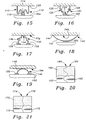
- the seat assemblies device 160 consist of a pair of seat platforms 162 meshed or dove-tailed together at a mesh area 164. Although meshed together, the seat platforms 162 still rock, move vertically, and are provided at a neutral angle in the same manner as that described above.
- the mesh area 164 has a sinusoidal shape.
- Both meshed seat platforms 162 are covered by a single cushion and/or upholstery 166. Meshing the seat platforms 162 and covering them with a single cushion and/or upholstery 166 still provides all the benefits described above relating to providing a neutral angle and two types of motion in the seat assemblies, and eliminates any demarcation or visible split between the seat assemblies. Eliminating this split makes the visible upper surface of the seat more aesthetically appealing, prevents crumbs and other debris from collecting in the crevice formed by this split, and prevents the occupant from getting his or her fingers, hands, arms, legs, or clothing caught in this area.
- the seat assemblies 170 consist of a pair of seat platforms 172 that are meshed or dove-tailed together at a mesh area 174.
- the mesh area 174 has a toothed design.
- the seat platforms also may be covered by a single cushion and/or upholstery 176.
- the seat platforms 36 illustrated in Figure 2 may be covered with a single cushion and/or upholstery 166 to provide the advantages mentioned above.
- This construction may provide more of a demarcation between the seat platforms 36 than the dove-tailed seats 160, 170, but still makes the visible upper surface of the seat more aesthetically appealing, prevents crumbs and other debris from collecting in the crevice formed by a split seat assembly, and prevents the occupant from getting his or her fingers, hands, arms, legs, or clothing caught in this area.
Landscapes
- Engineering & Computer Science (AREA)
- Mechanical Engineering (AREA)
- Aviation & Aerospace Engineering (AREA)
- Transportation (AREA)
- Public Health (AREA)
- Combustion & Propulsion (AREA)
- Animal Behavior & Ethology (AREA)
- General Health & Medical Sciences (AREA)
- Health & Medical Sciences (AREA)
- Veterinary Medicine (AREA)
- Chemical & Material Sciences (AREA)
- Life Sciences & Earth Sciences (AREA)
- Ocean & Marine Engineering (AREA)
- Chairs Characterized By Structure (AREA)
- Chair Legs, Seat Parts, And Backrests (AREA)
- Motorcycle And Bicycle Frame (AREA)
- Seats For Vehicles (AREA)
- Special Chairs (AREA)
- Floor Finish (AREA)
Abstract
Description
- This invention relates to a seat according to the preamble of claim 1 (see US-A-5 024 485).
- Most seats in the past did not promote occupant movement. Seats that do not promote occupant movement cause the seated occupant to sit in a constrained or static posture. This can lead to a number of health-related problems. For example, constrained occupant seating postures can cause joint impairments (arthritis), inflamed tendon sheaths (tendinitis, peritendinitis), chronic joint degeneration (arthroses), and muscle pain (e.g., when the occupant shifts weight on the seat bones, from side to side, or leans to one side, the occupant stresses his or her back muscles to remain adequately supported on the seat).
- Prolonged static seating has also been linked to back problems because of the prolonged static pressure on the spine. Prolonged static pressure on the spine impairs fluid flow from the discs, impairing glucose transport, disc nutrition, and the elimination of waste products.
- Constrained occupant postures also cause poor circulation. Edema of the lower legs is commonly induced by lack of movement. Leg edema is problematic because local pooling of the blood increases venous pressures to the heart, blood pressure, and heart rate. Edema may predispose the occupant to varicose veins, hemorrhoids, and other peripheral venous disorders such as cold feet. Another circulation problem resulting from seats that do not promote occupant movement is deep venous thrombosis caused by the formation of venous clots in the legs. These blood clot formations occur from sitting in a static position for long periods of time. Other circulation problems occur when certain parts of the occupant's posterior or legs experience greater pressure than the portion of the seat, especially the front, digs into the other seated portions of the occupant. This occurs when a posterior or legs of the occupant, or if the occupant leans more towards one side of the seat than the other. These concentrated forces on the legs and posterior inhibit circulation and lead to discomfort.
- Some seats have been designed to promote occupant movement and improve the comfort of the seated occupant. Some of these seats include a pair of seat platforms that move independently of each other. Each seat platform rocks in a see-saw manner on a fulcrum. In one of these seats, the fulcrum also allows vertical movement of the seat platform as the seat platform slides backwards and forwards. The independent seat platforms are designed to be self aligning, and allow the posterior of the occupant to move normally and independently without restraint, improving seat comfort.
- The problem with these seats is that they are not comfortable for multiple seating applications and environments (e.g., office, home, automobile, etc.). In most seating environments, these seats do not properly distribute the weight of the body being borne by the ischial tuberosities ("seat bones") and the residual weight of the posterior and thigh over the two seating platforms during different seat positions (e.g., one leg up, both legs up, both legs down, legs crossed, etc.). This causes discomfort and circulation problems. Also, in most seating environments, the seats did not allow the exercise necessary for the muscles, tendons, and ligaments of the lower back, pelvis, and thigh areas. This leads to circulation problems, flexibility problems, and back problems.
- An object of the present invention is to overcome the above-described difficulties of static seating.
- An aspect of the present invention involves the recognition that in a seat with a pair of moving seat assemblies, optimal seating comfort is achieved by providing the seat assemblies at a predetermined neutral angle appropriate for the particular application of the seat. The neutral angle is defined as the angle, relative to horizontal, at which the seat assemblies are initially oriented before external forces are applied to the seat. It is further recognized that each seat assembly should rock and move vertically up to a predetermined amount corresponding to the neutral angle.
- Another aspect of the present invention involves four additional recognitions. First, in greater positive neutral angle seating applications (leaned-back seating), the amount of rocking and vertical movement should be greater. Second, in smaller positive neutral angle seating applications, the amount of rocking and vertical movement should be smaller. Third, in greater negative neutral angle seating applications (leaned-forward seating), the amount of rocking movement should be greater, but the amount of vertical movement should be smaller. Finally, in smaller negative neutral angle seating applications, the amount of rocking and vertical movement should be smaller.
- An additional aspect of the present invention involves a seat with a pair of moving seat assemblies. A motion mechanism allows vertical motion and rocking motion in each seat assembly. The seat assembly is provided at a neutral angle based on the application of the seat. The total amount of rocking motion and vertical motion allowed depends on the neutral angle of the seat assembly. This combination causes the weight of a seated occupant borne by the ischial tuberosities and the residual weight of the posterior and thighs to be distributed optimally over the two seating assemblies, regardless of the occupant's seated position. The combination also allows the muscles, tendons, and ligaments of the lower back, pelvic, and thigh areas to be exercised, improving fluid flow (e.g., blood circulation), alertness, flexibility, and inhibiting back pain.
- These and other features of the invention will now be described with reference to the drawings which are intended to illustrate and are not to limit the invention, and in which:
- Figure 1 is a perspective view of an office chair with an embodiment of the two platform motion seat of the present invention incorporated therein;
- Figure 2 is an exploded view of an embodiment of the seat assemblies of the two platform motion seat of the present invention;
- Figure 3 is a cross-sectional view of the two platform motion seat of Figure 1, taken along line 3-3 of Figure 1;
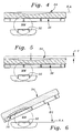
- Figure 4 is a cross-sectional view of the two platform motion seat of Figure 1, taken along line 4-4 of Figure 1, and shows the motion mechanism (MM) symbolically and the seat assembly;
- Figure 5 is a cross-sectional view, similar to Figure 4, and shows the vertical movement capability of the seat assembly;
- Figure 6 is a cross-sectional view, similar to Figures 4 and 5, and shows the rocking capability of the seat assembly through a positive angle (1);
- Figure 7 is a cross-sectional view, similar to Figures 4-6, and shows the rocking capability of the seat assembly through a negative angle (2);
- Figure 8 is a symbolic representation of the motion mechanism MM and the seat assemblies, and shows the seat assemblies at different rocking angles (1, 2) and with different amounts of vertical movement (V 1 , V 2 );
- Figures 9A-9C are symbolic representations of the motion mechanism MM and the seat assembly, and show the seat assembly at various neutral angles (α);
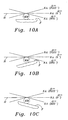
- Figures 10A-10C are symbolic representations of the motion mechanism MM and the seat assembly, and show the seat assembly at various neutral angles and the foundation F at various angles;
- Figures 11 - 19 show alternative embodiments of the motion mechanism of the present invention; and
- Figures 20-21 show a top plan view of alternative embodiments of the seat assemblies of the two platform motion seat of the present invention.
-
- With reference to Figure 1, a two
platform motion seat 20 constructed in accordance with an embodiment of the invention is shown incorporated into anoffice chair 22. Thechair 22 includes aback 24,arms 26, andlegs 28. On opposite sides of thechair 22, anapron 30 connects an upper part of thelegs 28. A support orfoundation 32 extends laterally across thechair 22 and is supported by theaprons 30. The twoplatform motion seat 20 is supported by thelateral support 32. - Although the two
platform motion seat 20 is shown and described in conjunction with anoffice chair 22, it will be readily understood by the reader that an office chair is just one of the many seating applications or environments that the two platform motion seat of the present invention may be incorporated into. For example, but not by way of limitation, the two platform motion seat of the present invention may also be incorporated into the following types of seats: task (e.g., assembly line seating), auto, light trucks, long-haul trucking, military vehicles, heavy equipment, tractors, auditorium, theater, stadium, institutional, formal, leisure, dining furniture, motion (e.g., recliners), rocking, stationary furniture (e.g., dining room chairs), folding chairs, stacking chairs, airline, bus, train, motorcycles, golf carts, wheelchair, exercise devices, stools, sit/stand chairs, and handheld, after-market portable seats. - In addition, the seat that the two
platform motion seat 20 is incorporated into may include, but not by way of limitation, any of the following improvements that are not shown: headrests, armrests, legrests, manual or power adjustment mechanisms, heating/cooling -devices, and vibration/massage mechanisms. For example, the two platform motion seat may include any of the manual user adjustment mechanisms (e.g., seat height control mechanism, tilt control mechanism, etc.) found on many modem chairs. - With reference to Figure 2, the two
platform motion seat 20 includes a pair ofadjacent seat assemblies 34. Eachseat assembly 34 has a seat platform orbody 36, which may be made of metal, plastic, a frame with webbing, or an inflatable device. Theseat body 36 may have a generally rectangular shape and includes amain body 38 and aperiphery 40. Themain body 38 may have contouring of any shape for additional seating comfort. Theperiphery 40 may include aflanged portion 42. Theseat body 36 may include a set ofholes 44 in themain body 38 and a set ofholes 46 in theperiphery 40. - Although not shown, the
seat body 36 may be subdivided into two or more subsections, laterally or longitudinally. The subsections of theseat assemblies 34 may rock and move vertically in the manner described more fully below. Subdividing theseat body 36, especially subdividing theseat body 36 into movable subsections, makes theseat body 36 more responsive to the movements of the seated occupant. - Each
seating assembly 34 may include acushioning material 48 and/or an outer upholstery covering 50. The cushioningmaterial 48 andupholstery 50 may be attached onto theseat body 36 with threaded fasteners (not shown), which fit through the periphery holes 46, or with any other suitable fastening means such as glue. The cushioningmaterial 48 and/orupholstery 50 may be contoured for additional seating comfort. It should be noted, in certain seating applications (e.g., outdoor stadium seating), the cushioningmaterial 48 and/orupholstery 50 might not be added. - With reference to Figures 3-7, the
seating assemblies 34 preferably move independently of each other through at least one motion mechanism, which is represented symbolically as MM in order for the reader to better understand the motion and orientation provided in the two platform motion seat of the present invention. Although one motion mechanism MM is preferably provided for each seatingassembly 34, a single motion mechanism MM may be provided for both seating assemblies, or multiple motion mechanisms MM may be provided for each seatingassembly 34. The motion mechanism MM provides theseating assembly 34 with vertical motion and rocking motion. A number of embodiments of the motion mechanism MM are shown in Figures 11-19 and described below. Although these embodiments of the motion mechanism MM include different types of spring arrangements, it will be readily understood by the reader that other types of motion mechanisms MM may be used, such as, but not by way of limitation, pneumatic mechanisms (e.g., air bladder), hydraulic mechanisms, magnetic mechanisms, or motorized mechanisms (in conjunction with sensor arrangement, control circuit, and/or computer). It should also be noted that theseating assemblies 34 do not have to move completely independently of each other; the movement of the seating assemblies may be interrelated. - With reference to Figures 3-5, the vertical or up-and-down motion of the
seat assembly 34 will now be described. When seated, an occupant sits generally upon his or her ischial tuberosities or seat bones. The weight of the occupant generally creates a pair of respective resultant forces R.S., L.S. on theseat assemblies 34. Each motion mechanism MM allows itsseat assembly 34 to travel downwards a respective distance V (Figure 5) corresponding to the magnitude of the force R.S., L.S. on it. When the force R.S., L.S. is removed from theseat assembly 34, the motion mechanism MM causes theseat assembly 34 to rise vertically to its original position (Figure 4). - In traditional seats that do not have independent moving seat halves, when the occupant shifts weight on the seat bones, from side to side, or leans to one side, the occupant stresses his or her back muscles to remain adequately supported on the seat. Not only does this cause discomfort in the lower back, but the concentrated load on the side of the posterior that the occupant is leaning to causes discomfort.
- The motion mechanism MM provides the
seat assemblies 34 with the independent vertical motion the pelvis requires to accommodate shifting weight on the seat bones, from side to side, and maintain a balanced weight distribution between the two seat bones. This allows the pelvis to perform its role as the "fulcrum of the body" while seated, just as it does while standing, walking, or running. When standing, walking, or running, the pelvis serves as a balance or pivot point for the upper body, adjusting when the occupant shifts weight from side to side. In traditional seats, the pelvis is restricted from functioning as a balance or pivot point. Consequently, the weight of the upper and lower body is not balanced properly on the seat. The motion mechanism MM provides enough movement to allow the pelvis to function effectively as a pivot point. This provides proper weight distribution for the occupant's upper and lower body, leading to the proper adjustment of the spine, and allowing the occupant to be better supported on the seat. This inhibits lower back pain because the back muscles are not stressed to maintain balance and helps reduce the aforementioned concentrated loads on one side of the posterior. - The inventors have determined that this vertical distance V should range from approximately 0.1 in. to 4.0 in., depending on the neutral angle, which will be described in more detail below, and the particular seating application. If the amount of vertical movement is less than approximately 0.1 in., the inventors have determined that the
seating assembly 34 would provide insufficient movement to the pelvic bones to allow for proper adjustment of the spine and maintain a balanced weight distribution between the two ischial tuberosities. Also, if the amount of up-down motion is too small the seat will feel too hard, creating too much static pressure on the ischial tuberosities. If the amount of vertical movement is greater than approximately 4.0 in., theseating assembly 34 can result in unstable postures and/or the creation of additional stress on the muscles to maintain balance. While approximately 0.1 to 4.0 in.is believed to be the desired range of movement. At least about 0.8 in. is more preferable for numerous applications because it prevents the seat from feeling too hard and allows for a more stable posture. - Figures 6 and 7 illustrate the rocking or see-saw motion of the
seat assembly 34. When an occupant sits on theseat assemblies 34, the occupant's location on theseat assemblies 34 and his or her seating posture will cause eachseat assembly 34 to rock to a rocking angle through the motion mechanism MM. The rocking angle is the angle that the seat assembly rocks through, relative to the initial, unburdened orientation or neutral angle disposition NA of the seat. For rocking angle calculation purposes, the neutral angle disposition NA of the seat is considered to be the origin or 0°. Although in Figures 3-7 the neutral angle disposition NA is horizontal, it will become better understood below that the neutral angle disposition NA varies, depending on the particular application of theseat 20. - The independent rocking motion of the
seat assemblies 34 provided by the motion mechanism MM allows eachseat assembly 34 to move in the above-described rocking manner with the movements of the occupant, optimally distributing the weight of the occupant over theseat assemblies 34 so as to inhibit discomfort and/or circulation problems. The rocking movement causes exercising of the muscles, tendons, and ligaments in the lower back, pelvic, and thigh areas by causing movement in these areas of the body. This promotes circulation, feeding nutrients, eliminating waste metabolites, and inhibiting leg swelling (edema), blood clotting, and other peripheral venous disorders. This exercise also feeds inter-vertebral discs through passive changes in osmosis. Movement-induced changes of pressure "feed" inter-vertebral discs nutrients and eliminate waste products by passive diffusion. This enhances the cushion effect the discs have on the occupant's vertebrae, reducing back problems caused by sitting. The movement also increases occupant alertness as afferent nerves send impulses to the central nervous system. Occupant comfort is also increased because the seat movement constantly redistributes pressures acting on the spine, joints, and tissue. - The
seat assembly 34 of Figure 6 is shown at a rocked back angle 1, (>0°). Theseat assembly 34 of Figure 7 is shown at a rocked-forward angle 2 (<0°). When the occupant leaves theseating assemblies 34, each motion mechanism MM causes itsseat assembly 34 to return to its initial, unburdened orientation (Figure 4). - The inventors have determined that preferably the total rocking angle or amount of total rock that the
seat assembly 34 can be rocked through is approximately 60° (from an extreme rocked-backward position to an extreme rocked-forward position). If the amount of total rock is too small, the inventors believe the occupant will not receive sufficient exercise and range of motion in the pelvic and thigh areas to provide the benefits of enhanced circulation, flexibility, and alertness. If the amount of total rock is greater than approximately 60°, the inventors believe the occupant will be placed in unstable postures and this will produce additional stress on the muscles to maintain balance. - With reference to Figure 8, although the vertical motion and rocking motion provided by the motion mechanism MM have been described separately, in actuality, these two motions are provided simultaneously by the motion mechanism MM. The
seating assemblies 34 are shown with different vertical movements V 1 , V 2 , and different rocking angles 1 , 2 , respectively. Theseat assemblies 34 might take this disposition when an occupant crosses his or her legs. - With reference to Figures 9A-9C, the inventors have recognized that to realize the aforementioned benefits from vertical motion and rocking motion in a two platform motion seat, which have not been achieved in a moving two platform seat for most seating applications in the past, each seating
assembly 34 must be provided at a neutral angle α appropriate for the particular seating application or environment that the twoplatform motion seat 20 is incorporated into. The inventors have further recognized that the amount of rocking motion and vertical motion provided by the motion mechanism MM should depend on this neutral angle α. - The neutral angle α is the absolute angle between the neutral angle disposition or line NA and an imaginary horizontal line H that resides at 0°. The neutral angle α is the angle that the
seating assembly 34 initially is oriented at before any external forces, such as the weight of the occupant, are applied to theseat 20. The horizontal line H is orthogonal to earth's gravity force vectors G (Figure 9A). Consequently, as illustrated in Figures 10A-10C, the orientation of thesupport 32 or foundation F is irrelevant in determining the neutral angle α because the neutral angle α is an absolute angle relative to the horizontal line H. - It will be apparent to one skilled in the art that the neutral angle disposition NA of the
seating assemblies 34 may be provided in numerous ways such as, but not by way of limitation, altering the angle of the foundation orsupport 32, altering the connection of the motion mechanism MM with the foundation or with the bottom of theseat body 36, changing the construction or configuration of the motion mechanism MM, etc. - Figure 9B illustrates the
seating assembly 34 with a positive neutral angle α 1 (α >0°). The inventors refer to seating applications with a positive neutral angle as leaned-back seating applications because the occupant predominantly sits in a leaned-back manner. Figure 9C illustrates theseat assembly 34 with a negative neutral angle α 2 . The inventors refer to seating applications with a negative neutral angle as leaned-forward seating applications because the occupant predominantly sits in a leaned-forward manner. - The inventors have determined that, in general, the neutral angle α should vary from approximately negative 40° to approximately positive 30°. In some seating applications, the neutral angle α may exceed these parameters. For example, in a sit-stand chair, the neutral angle α may exceed approximately negative 40° ° (e.g. negative 45 °, 50 °, etc.). In more modem, super reclining office chairs, the neutral angle α may sometimes exceed approximately positive 30° (e.g. positive 35°, 40°, etc.). In most seating applications, if the neutral angle α exceeds approximately negative 40°, the occupant would not be able to derive sufficient benefit from the vertical movement in the seat because the majority of the occupant's weight would be on his/her legs rather than on the ischial tuberosities. Similarly, in most seating applications, if the neutral angle α exceeds approximately positive 30°, the occupant would not be able to derive sufficient benefit from the movement in the seat because the majority of the occupant's weight would be on his/her back rather than on the ischial tuberosities.
- The varying of the neutral angle α for the two main types of seating applications, leaned-back seating (positive neutral angle seating) and leaned-forward seating (negative neutral angle seating) are described below.
- It should be noted, although two main types of seating are described, in some seating applications, such as office seating, a seat may be adjustable so as to provide a positive neutral angle α 1 and a negative neutral angle α 2 . This may be done with an adjustment mechanism (not shown) provided along the side of the
seating assemblies 34, below theseating assemblies 34, etc., to vary the neutral angle α of the seat between a positive neutral angle α 1 and negative neutral angle α 2 , including various positions therebetween. - Positive neutral angle or leaned-back seating applications generally consists of three different types: 1) minimum neutral angle (α = 0 to 4°); 2) moderate neutral angle (α = 0 to 15°); and 3) maximum neutral angle (α = 0 to 30°).
- The inventors have determined that the greater the neutral angle seating (i.e., moderate to maximum neutral angles), the greater the rocking movement and vertical movement should be in the seat assemblies 34 (It should be noted, the inventors have also determined the rocking movement and vertical movement should be relatively increased as cushion thickness increases). In this type of seating, the occupant is more reclined in the seat. This means less of the occupant's seated upper body weight is directed vertically downward on the spine and ischial tuberosities compared to minimum neutral angle seating where the occupant is essentially sitting vertically. Because of the smaller amount of stress on the spine and ischial tuberosities at this orientation, more movement, both vertical and rocking, is required in the
seat assemblies 34 for the occupant to experience stress relief in the normally-affected areas of the body. - The inventors have determined that the smaller the neutral angle seating (i.e., minimum to moderate neutral angles), the smaller the rocking movement and vertical movement should be in the
seat assemblies 34. In this type of seating, the occupant is sitting essentially upright. Thus, more of the occupant's upper body weight is directed vertically downward on the spine and ischial tuberosities. This greater stress means that only relatively small amounts of vertical and rocking movement are required for the occupant to feel stress relief in the normally-affected areas of the body. - The following identifies the desired parameters for rocking motion and vertical motion in the
seat assemblies 34 for the different types of leaned-back seating applications: - 1) Minimum Neutral Angle:
In minimum neutral angle seating, the neutral angle α is relatively
small (α = 0 to 4°). Examples of this type of seating include, but not by
way of limitation, office chair seating and task chair seating. Based on
the above neutral angle range, the amount of total rock should be
between approximately 5 and 10 degrees. If the amount of total rock is
greater than approximately 10 degrees, the inventors believe the
seating assemblies 34 will not adequately support the occupant, possibly resulting in an unstable posture that may produce additional stress on the muscles to maintain balance. If the amount of total rock is less than approximately 5 degrees, the inventors believe the occupant will not receive sufficient exercise and range of motion in the pelvic and thigh areas to provide the benefits of enhanced circulation, flexibility, and alertness. Based on this neutral angle range, the amount of vertical movement should be approximately 0.10 - 1.5 in.. If the amount of vertical movement is less than approximately 0.10 in., the seat may feel too hard, creating too much static pressure on the ischial tuberosities, and likely provides insufficient movement to the pelvic bones to allow for proper adjustment of the spine, or to maintain a balanced weight distribution between the two ischial tuberosities. If the amount of vertical movement is greater than approximately 1.5 in., the seat may not feel like it is providing adequate support. This may result in unstable postures and/or the creation of additional stress on the muscles to maintain balance. - 2) Moderate Neutral Angle:
In moderate neutral angle seating, the neutral angle α is small to
moderate (α = 0 to 15°). Examples of this type of seating include, but
not by way of limitation, motor vehicle seating such as automobile
seating. Based on the above neutral angle range, the amount of total
rock should be between approximately 3 and 20 degrees. If the amount
of total rock is greater than approximately 20 degrees, the inventors
believe the
seating assemblies 34 will not adequately support the occupant, possibly resulting in an unstable posture that may produce additional stress on the muscles to maintain balance. If the amount of total rock is less than approximately 3 degrees, the inventors believe the occupant will not receive sufficient exercise and range of motion in the pelvic and thigh areas to provide the benefits of enhanced circulation, flexibility, and alertness. Based on this neutral angle range, the amount of vertical movement should be approximately 0.25 - 2.0 in.. If the amount of vertical movement is less than approximately 0.25 in., the seat may feel too hard, creating too much static pressure on the ischial tuberosities, and likely provides insufficient movement to the pelvic bones to allow for proper adjustment of the spine and to maintain a balanced weight distribution between the two ischial tuberosities. If the amount of vertical movement is greater than approximately 2.0 in., the seat will not feel like it is providing adequate support. This may result in unstable postures and/or the creation of additional stress on the muscles to maintain balance.In seating applications such as automobile seating, where the occupant may be sitting in one position for a long period of time, motion in the seat is especially important to inhibit the formation of venous clots in the legs (i.e., deep venous thrombosis). These blood clot formations occur more frequently in people with poor circulation (e.g., the elderly) who sit in a static position for long periods of time. Deep venous thrombosis is a serious problem because if the clot breaks off and travels through the circulatory system it can lead to greater problems such as a pulmonary embolism. Varying the neutral angle with the particular seating application, and providing the rocking motion and vertical motion parameters indicated above passively exercises the normally-affected seating areas of the occupant, improving circulation and reducing the risk of deep venous thrombosis. - 3) Maximum Neutral Angle:
-
- In maximum neutral angle seating, the neutral angle α ranges from small to large (α = 0 to 30°). Examples of this type of seating include, but not by way of limitation, recliner, theater, and airline seating. Based on the above neutral angle range, the amount of total rock should be between approximately 10 and 60 degrees. If the amount of total rock is greater than approximately 60 degrees, the inventors believe the
seating assemblies 34 will not adequately support the occupant, possibly resulting in an unstable posture that may produce additional stress on the muscles to maintain balance. If the amount of total rock is less than approximately 10 degrees, the inventors believe the occupant will not receive sufficient exercise and range of motion in the pelvic and thigh areas to provide the benefits of enhanced circulation, flexibility, and alertness. Based on this neutral angle range, the amount of vertical movement should be approximately 0.5 - 4.0 in.. If the amount of vertical movement is less than approximately 0.5 in., the seat may feel too hard, creating too much static pressure on the ischial tuberosities, and likely provides insufficient movement for the pelvic bones to allow for proper adjustment of the spine and to maintain a balanced weight distribution between the two ischial tuberosities. If the amount of vertical movement is greater than approximately 4.0 in., the seat will not feel like it is providing adequate support. This may result in unstable postures and/or the creation of additional stress on the muscles to maintain balance. - Negative neutral angle or leaned-forward seating applications generally consist of moderate neutral angle to maximum neutral angle seating (α = 0 to -40°).
- The inventors have determined that the larger the negative neutral angle seating (i.e., moderate to maximum negative neutral angles), the greater the rocking movement required, but the smaller the amount of vertical movement required. At moderate to maximum negative neutral angles, the legs of the occupant relieve more of the stress on the ischial tuberosities (i.e., receive a larger portion of the gravitation force) and provide some of the vertical movement required. Thus, less vertical movement is needed in the
seating assemblies 34. Relatively large rocking motions are required to ensure the weight on the posterior is optimally distributed over the seating assemblies, and the muscles, tendons, and ligaments of the occupant are passively exercised. The smaller the negative neutral angle seating (minimum to moderate negative neutral angles), similar to positive neutral angle seating above, the smaller the amount of rocking motion and vertical motion required. - In moderate to maximum negative neutral angle seating, the neutral angle α ranges from small to large (α = 0 to -40°). Examples of this type of seating include, but not by way of limitation, sit-stand chair seating. Based on the above neutral angle range, the amount of total rock should be between approximately 10 and 60 degrees. If the amount of total rock is greater than approximately 60 degrees, the inventors believe the
seating assemblies 34 will not adequately support the occupant, either barely or not supporting the occupant, or creating an unstable posture that may produce additional stress on the muscles to maintain balance. If the amount of total rock is less than approximately 10 degrees, the inventors believe the occupant will not receive sufficient exercise and range of motion in the pelvic and thigh areas to provide the benefits of enhanced circulation, flexibility, and alertness. Based on this neutral angle range, the amount of vertical movement should be approximately 0.1 - 1.5 in.. If the amount of vertical movement is less than approximately 0.1 in., the seat may feel too hard, creating too much static pressure on the ischial tuberosities, and likely provides insufficient movement to the pelvic bones to allow for proper adjustment of the spine and to maintain a balanced weight distribution between the two ischial tuberosities. If the amount of vertical movement is greater than approximately 1.5 in., the seat will not feel like it is providing adequate support. This may result in unstable postures and/or the creation of additional stress on the muscles to maintain balance. - Providing the
seating assemblies 34 at a specific neutral angle α based on the particular seating application and providing a specific amount of vertical motion and rocking motion based on the specific neutral angle α produces a dynamic seating surface that is specifically designed for each individual seating application. The specific neutral angle α of the seating assemblies properly orients the occupant so that he or she can take full advantage of the aforementioned benefits provided by the two types of motion in theseating assemblies 34. - The vertical motion along with the rocking motion provides the independent motion the pelvis requires to accommodate shifting weight on the ischial tuberosities, from buttock to buttock. This allows the pelvis to perform its role as the "fulcrum of the body" while seated, just as it does while standing, walking, or running. Combined, these motions serve to distribute the weight of the body being borne by the ischial tuberosities and the residual weight of the posterior and thighs optimally over the two seating surfaces, regardless of the position one is sitting in (one leg up, one leg down, both legs up, both legs down, legs crossed, etc.). These motions also cause exercising of the muscles, tendons, and ligaments in the lower back, pelvic, and thigh areas by causing muscle pumping action in these areas of the body. This promotes circulation, feeding nutrients, eliminating waste metabolites, and inhibiting leg swelling (edema), blood clotting, and other peripheral venous disorders. The movement also increases occupant alertness as afferent nerves send impulses to the central nervous system. Occupant comfort is also increased because the seat movement constantly redistributes pressures acting on the spine, joints, and tissue. The rocking motion also eliminates restricted circulation problems caused by a portion of the seating surface, especially the front edge, cutting into the posterior or thighs of the occupant.
- With reference to Figures 11-19, numerous embodiments of the motion mechanism of the present invention will now be described. These motion mechanisms are preferably made of steel, plastic, or similar material. Where appropriate, like reference numbers with an "a," "b," "c," etc. suffix have been used to indicate like parts previously described for ease of understanding.
- With reference to Figure 11, an embodiment of a
motion mechanism 76 is disclosed. Themotion mechanism 76 includes aspring 78 with a wave-like shape. The wave-like spring 78 includes afirst crest portion 80 with aflange 82. Theflange 82 includes a threadedfastener 84 for attaching thespring 78 to theseat body 36a of theseat assembly 34a. Thespring 78 includes afirst trough portion 85 that rests upon thelateral support 32a. Thefirst trough portion 85 is attached to thesupport 32a with a threaded fastener. The wave-like spring 78 also includes asecond crest portion 86, which supports another area of theseat body 36a and asecond trough portion 88 that rests upon one of theaforementioned aprons 30a. - With reference to Figure 12, a
motion mechanism 90 constructed in accordance with an additional embodiment of the invention is shown. Themotion mechanism 90 includes a pair ofhelical springs 92 that rest upon the lateral support 32b. Thesprings 92 may be varied by size or type to obtain the desired amount of rocking and vertical motion. - With reference to Figure 13, a
motion mechanism 94 constructed in accordance with an additional embodiment of the invention is shown. Themotion mechanism 94 includes first andsecond springs first spring 96 rests upon arigid base 110 and supports a rearward portion of theseating assembly 34c. Thesecond spring 98 rests upon theapron 30c and supports a forward portion of theseat assembly 34c. As mentioned above, the size and types of thesprings - With reference to Figure 14, a
motion mechanism 100 constructed in accordance with an additional embodiment of the invention is shown. Themotion mechanism 100 includes amain body portion 102 and a pair ofleg portions 104. Themain body portion 102 includes a flat plate 106 that supports theseat assembly 34d. The flat plate 106 of themotion mechanism 100 is attached to theseat assembly 34d with a threaded fastener or similar fastening means. Theleg portions 104 have a sinusoidal-like shape and terminate inrespective flanges 108. Theflanges 108 are connected to a foundation F with threaded fasteners. - With reference to Figure 15, a
motion mechanism 112 constructed in accordance with an additional embodiment of the invention is shown. Themotion mechanism 112 is the same as themotion mechanism 100 described above, except its orientation is reversed. Themotion mechanism 112 includes amain body portion 114 and a pair ofleg portions 116. Themain body portion 114 includes aflat plate 118 that rests upon thesupport 32e. Theflat plate 118 is connected to thesupport 32e with a threaded fastener or similar fastening means. Theleg portions 116 have a sinusoidal-like shape and terminate inrespective flanges 120. Theflanges 120 are connected to the underside of the seat assembly 34e with threaded fasteners or similar fastening means. - With reference to Figure 16, a
motion mechanism 122 constructed in accordance with an additional embodiment of the invention is shown. Themotion mechanism 122 includes amain body portion 124 that rests upon thelateral support 32f. Themain body portion 124 is attached to thelateral support 32f with threaded fasteners or similar fastening means. A pair of step-shapedleg portions main body portion 124. The step-shapedleg portions flanges 130. Theflanges 130 support theseat assembly 34 and are connected thereto with threaded fasteners or similar fastening means. - With reference to Figure 17, a
motion mechanism 132 constructed in accordance with an additional embodiment of the invention is shown. Themotion mechanism 132 is the same as themotion mechanism 122 described above, except its orientation is reversed. Themotion mechanism 132 includes amain body portion 134 that supports theseat assembly 32g. A pair of step-shapedleg portions 136 extend from opposite sides of themain body portion 134 and terminate in a pair offlanges 138. Theflanges 138 rest upon a pair of lateral supports 139. - With reference to Figure 18, a
motion mechanism 140 constructed in accordance with an additional embodiment of the invention is shown. Themotion mechanism 140 includes an elongated, upward-facing, arch-shapedmember 142 or leaf spring that terminates at opposite ends inflanges 144. Theflanges 144 support theseating assembly 34h and are connected thereto with threaded fasteners or similar fastening means. Themotion mechanism 140 is connected to thelateral support 32h at its midpoint. - With reference to Figure 19, a
motion mechanism 146 constructed in accordance with an additional embodiment of the invention is shown. Themotion mechanism 146 is similar to themotion mechanism 140 described above, except its orientation is reversed. Themotion mechanism 146 includes an arch-shapedmember 148 that terminates at opposite ends inflanges 150. Theflanges 150 rest upon respective lateral supports 152 and are connected thereto. The arch-shapedmember 148 is connected toseat assembly 34i at its apex. - The ideal location in the
seat 20 for the occupant to sit is called the ischial tuberosities target area. This is the area of theseating assembly 34 where an occupant's ischial tuberosities ("seat bones") should be placed to obtain maximum comfort, optimal movement, and to obtain the greatest weight distribution benefit. This area is positioned approximately over the motion mechanism and extends longitudinally approximately the distance between the flanges or contact points between the motion mechanism and theseat assembly 34. The size of the ischial tuberosities target area depends on the size and construction of the motion mechanism. The ischial tuberosities target area ideally extends up to 5 in. longitudinally forward and rearward (10 in. total) from the point in the seating assembly over the center of the motion ° mechanism and can extend transversely as wide as theseating assembly 34. - The ischial tuberosities target area was much smaller in rocking seats of the past. Some of these seats included an arch-shaped assembly that attached to the seat at its apex. The apex narrowly defined the ischial tuberosities target area because an occupant had to be seated approximately directly over the apex to take full advantage of the comfort provided by the motion of the seat. This was sometimes difficult because every occupant has a different seating position. A number of the motion mechanism embodiments of the present invention (See Figures 11, 13, 15, 16, 18) expand the ischial tuberosities target area because they longitudinally extend the target area to approximately the distance between the flanges or contact points. The larger target area ensures that the occupant sits in the proper area of the seat to achieve maximum comfort and other benefits described above.
- With reference to Figures 20 and 21, and initially to Figure 20, a pair of seat assemblies, indicated generally by the
reference numeral 160 and constructed in accordance with an alternative embodiment of the invention, will now be described. Theseat assemblies device 160 consist of a pair ofseat platforms 162 meshed or dove-tailed together at amesh area 164. Although meshed together, theseat platforms 162 still rock, move vertically, and are provided at a neutral angle in the same manner as that described above. Themesh area 164 has a sinusoidal shape. - Both
meshed seat platforms 162 are covered by a single cushion and/orupholstery 166. Meshing theseat platforms 162 and covering them with a single cushion and/orupholstery 166 still provides all the benefits described above relating to providing a neutral angle and two types of motion in the seat assemblies, and eliminates any demarcation or visible split between the seat assemblies. Eliminating this split makes the visible upper surface of the seat more aesthetically appealing, prevents crumbs and other debris from collecting in the crevice formed by this split, and prevents the occupant from getting his or her fingers, hands, arms, legs, or clothing caught in this area. - With reference to Figure 21, an alternative embodiment of a pair of
seat assemblies 170 is shown. Theseat assemblies 170 consist of a pair ofseat platforms 172 that are meshed or dove-tailed together at amesh area 174. Themesh area 174 has a toothed design. The seat platforms also may be covered by a single cushion and/orupholstery 176. - It should be noted, in another embodiment of the invention, the
seat platforms 36 illustrated in Figure 2 may be covered with a single cushion and/orupholstery 166 to provide the advantages mentioned above. This construction may provide more of a demarcation between theseat platforms 36 than the dove-tailedseats - Although this invention has been described in terms of certain preferred embodiments, other embodiments apparent to those of ordinary skill in the art are also within the scope of this invention. Accordingly, the scope of the invention is intended to be defined only by the claims that follow.
Claims (12)
- A seat comprising:characterised in that the neutral angle is between approximately 0 and positive 15 degrees, wherein positive neutral angle means leaned-back seating,a pair of seating bodies, and at least one motion mechanism providing the seating bodies with a rocking motion and a vertical motion, each seating body having a predetermined neutral angle based on the particular application of the seat, wherein the neutral angle is the angle with respect to a horizontal axis orthogonal to the earth's gravity vectors that the seating body resides at when no external forces are present on the seating body, and wherein a predetermined amount of rocking motion and vertical motion are provided in each seating body by the at least one motion mechanism based on the neutral anglethe amount of vertical motion is between approximately 6 and 50 mm (0.25 and 2.0 inches), andthe total rocking motion is between approximately 3 and 20 degrees.
- The seat of claim 1, wherein the amount of vertical motion is at least 20 mm (0.8 inches).
- The seat of any preceding claim, wherein said motion mechanism provides an ischial tuberosities target area, said ischial tuberosities target area defined as the ideal location on the seating body for an occupant to sit, the ischial tuberosities target area extending about 127 mm(5 inches) in the longitudinal direction of the seating body forward of and about 127 mm(5 inches) rearward of said motion mechanism and up to the width of the seating body.
- The seat of claim 1, wherein the total rocking motion is greater when the neutral angle is greater.
- The seat of any preceding claim, wherein said seating bodies are covered by a single cushion.
- The seat of any one of claims 1 to 4, wherein each seating body is covered by a respective cushion.
- The seat of claim 5 or 6, wherein said seating bodies are meshed.
- The seat of any preceding claim, wherein the seating bodies move independently of each other.
- The seat of any preceding claim, wherein each seating body is subdivided into at least two movable subportions.
- The seat of any preceding claim, wherein each seating body is adjustable to provide multiple neutral angles.
- The seat of any preceding claim, wherein there are a pair of motion mechanisms, each respectively associated with one seating body, each motion mechanism providing its respective seating body with a rocking motion and a vertical motion, and each motion mechanism having at least two points of physical contact with its associated seat body.
- The seat of claim 1, wherein the vertical motion is greater when the neutral angle greater.
Applications Claiming Priority (5)
| Application Number | Priority Date | Filing Date | Title |
|---|---|---|---|
| US08/940,921 US5913568A (en) | 1997-09-30 | 1997-09-30 | Two platform motion seat |
| US940795 | 1997-09-30 | ||
| PCT/US1998/020287 WO1999016335A1 (en) | 1997-09-30 | 1998-09-28 | Two platform motion seat |
| US09/536,207 US6357827B1 (en) | 1997-09-30 | 2000-03-27 | Two platform motion seat |
| US10/057,192 US6595586B2 (en) | 1997-09-30 | 2002-01-25 | Two platform motion seat |
Publications (3)
| Publication Number | Publication Date |
|---|---|
| EP1026975A1 EP1026975A1 (en) | 2000-08-16 |
| EP1026975A4 EP1026975A4 (en) | 2001-02-07 |
| EP1026975B1 true EP1026975B1 (en) | 2005-08-17 |
Family
ID=43031554
Family Applications (2)
| Application Number | Title | Priority Date | Filing Date |
|---|---|---|---|
| EP98949580A Expired - Lifetime EP1026975B1 (en) | 1997-09-30 | 1998-09-28 | Two platform motion seat |
| EP01920706A Withdrawn EP1267668A4 (en) | 1997-09-30 | 2001-03-23 | Two platform motion seat |
Family Applications After (1)
| Application Number | Title | Priority Date | Filing Date |
|---|---|---|---|
| EP01920706A Withdrawn EP1267668A4 (en) | 1997-09-30 | 2001-03-23 | Two platform motion seat |
Country Status (9)
| Country | Link |
|---|---|
| US (4) | US5913568A (en) |
| EP (2) | EP1026975B1 (en) |
| JP (2) | JP2001517514A (en) |
| CN (1) | CN1209060C (en) |
| AT (1) | ATE301955T1 (en) |
| AU (3) | AU735768B2 (en) |
| CA (2) | CA2304603A1 (en) |
| DE (1) | DE69831259D1 (en) |
| WO (3) | WO1999016335A1 (en) |
Cited By (2)
| Publication number | Priority date | Publication date | Assignee | Title |
|---|---|---|---|---|
| WO2007043825A1 (en) * | 2005-10-14 | 2007-04-19 | Sun Whan Kim | Pelvis protecting chair |
| CN102488411A (en) * | 2011-12-21 | 2012-06-13 | 青岛理工大学 | Multifunctional chair |
Families Citing this family (228)
| Publication number | Priority date | Publication date | Assignee | Title |
|---|---|---|---|---|
| US5913568A (en) * | 1997-09-30 | 1999-06-22 | Brightbill; Stephen T. | Two platform motion seat |
| US6139095A (en) | 1998-12-31 | 2000-10-31 | Robertshaw; Richard C. | Split seat pelvic mobilizing chair |
| FR2808246B1 (en) * | 2000-04-27 | 2002-07-19 | Faure Bertrand Equipements Sa | MOTOR VEHICLE SEAT SEAT HAVING A MASSAGE EFFECT |
| IT1320197B1 (en) | 2000-05-25 | 2003-11-26 | Mondo Spa | SYNTHETIC GRASS COVER STRUCTURE, RELATIVE PARTICLE MATERIAL AND USE OF THE PARTICLE MATERIAL ITSELF. |
| US6481795B1 (en) | 2000-06-05 | 2002-11-19 | Burl Pettibon | Therapeutic chair |
| IT1321288B1 (en) * | 2000-06-07 | 2004-01-08 | Technogym Srl | GYMNASTIC TRAINING MACHINE. |
| CA2422015A1 (en) * | 2000-09-19 | 2002-03-28 | Han-Keel Yoo | Chair for correcting an improper alignment of spinal vertebrae and method for correcting an improper alignment of spinal vertebrae by means of the chair |
| DE20019569U1 (en) * | 2000-11-17 | 2001-01-11 | Meyer, Stephan, 79100 Freiburg | Seating device for seating |
| US7112168B2 (en) * | 2000-12-15 | 2006-09-26 | Icon Ip, Inc. | Selectively dynamic exercise platform |
| USD493500S1 (en) | 2000-12-15 | 2004-07-27 | William T. Dalebout | Top surface of an exercise device |
| USD505460S1 (en) | 2000-12-15 | 2005-05-24 | Reebok International Ltd. | Exercise device |
| JP4838451B2 (en) * | 2001-08-01 | 2011-12-14 | 有限会社ウド・エルゴ研究所 | Tilting chair |
| US20030032533A1 (en) * | 2001-08-13 | 2003-02-13 | Hecox Mark G. | Torsion exercise apparatus |
| US6878102B1 (en) * | 2001-08-21 | 2005-04-12 | Luis Alberto Commisso | Leg-ankle-foot exercise assembly |
| US7032972B2 (en) | 2001-11-01 | 2006-04-25 | Berman Irwin R | Resilient seating structure |
| NZ513331A (en) | 2001-11-20 | 2005-01-28 | Board & Batten Int Inc | Edge fittings for soft-edged trampolines |
| RU2199258C1 (en) * | 2002-02-14 | 2003-02-27 | Быков Алексей Алексеевич | Seating device |
| GB2388313A (en) * | 2002-05-09 | 2003-11-12 | Nissan Technical Ct Europ Ltd | Seating arrangement for a vehicle |
| JP4619116B2 (en) * | 2002-06-21 | 2011-01-26 | アプライド マテリアルズ インコーポレイテッド | Transfer chamber for vacuum processing system |
| US7033176B2 (en) * | 2002-07-17 | 2006-04-25 | Powergrid Fitness, Inc. | Motion platform system and method of rotating a motion platform about plural axes |
| US7226130B2 (en) * | 2002-09-12 | 2007-06-05 | Steelcase Development Corporation | Seating with comfort surface |
| US7008359B2 (en) * | 2002-10-18 | 2006-03-07 | Reebok International Ltd. | Exercise apparatus |
| USD489778S1 (en) | 2002-10-18 | 2004-05-11 | Reebok International Ltd. | Portion of an exercise device |
| AU2003223557A1 (en) * | 2002-10-29 | 2004-05-25 | Jeffrey S. Wilcox | Seat suspension |
| KR100397267B1 (en) * | 2003-06-12 | 2003-09-13 | 김선환 | Seat Apparatus Having Variable Gap |
| USD507311S1 (en) | 2003-08-27 | 2005-07-12 | Icon Ip, Inc. | Exercise device with elongated flexible member |
| FR2859175B1 (en) * | 2003-09-03 | 2005-11-25 | Messier Bugatti | VEHICLE SEAT WITH PILOT ACTUATOR |
| DE10348124B4 (en) * | 2003-10-16 | 2009-11-26 | Hardy Burbaum | Seat |
| WO2005053592A1 (en) * | 2003-12-01 | 2005-06-16 | Takao Nishi | Seat folding mechanism and wheel chair |
| US20060006704A1 (en) * | 2003-12-15 | 2006-01-12 | Be Aerospace, Inc. | Vehicle seating with storage feature |
| US7063384B2 (en) * | 2004-01-09 | 2006-06-20 | Huang Chang Liu | Flexible chair back |
| NL1025228C2 (en) * | 2004-01-13 | 2006-05-18 | Ergodynamics Applic B V | Seating support and working method for ergonomically supporting a seated person. |
| DE202004005366U1 (en) * | 2004-04-05 | 2004-06-24 | VS Vereinigte Spezialmöbelfabriken GmbH & Co. | Chair with rocker mechanism |
| GB0408366D0 (en) * | 2004-04-15 | 2004-05-19 | Kab Seating Ltd | Seat suspension system |
| US7044553B2 (en) * | 2004-06-22 | 2006-05-16 | Sears Manufacturing Co. | Vehicle seat suspension with omni directional isolator |
| JP4721254B2 (en) * | 2004-09-08 | 2011-07-13 | 俊壱 木原 | Chair |
| USD508182S1 (en) | 2004-09-16 | 2005-08-09 | Sylmark Holdings Limited | Seat cushion |
| JP2006122440A (en) * | 2004-10-29 | 2006-05-18 | Hsin Hao Hearth Materials Co Ltd | massage chair |
| ITFI20040265A1 (en) * | 2004-12-17 | 2005-03-17 | Enrico Tacconi | DEVICE FOR THE REHABILITATION OF ARTS AND TRUNK |
| ITMI20050759A1 (en) * | 2005-04-27 | 2006-10-28 | Selle Italia Srl | SADDLE STRUCTURE WITH SHOCK ABSORBER FOR CYCLING OR SIMILAR BICYCLES |
| CA2526108A1 (en) * | 2005-11-04 | 2007-05-04 | Steven Pearse | Chair having movable thigh levers |
| US20070205648A1 (en) * | 2006-03-06 | 2007-09-06 | Tsung-Chieh Huang | Elastic assembly of chair cushion |
| KR100784433B1 (en) | 2006-09-04 | 2007-12-11 | 김해용 | Detachable chair that can cope with changes in weight |
| US8439442B2 (en) * | 2006-09-29 | 2013-05-14 | Corewerks, Inc. | Method and apparatus to enhance proprioception and core health of the human body |
| US7686396B2 (en) * | 2006-09-29 | 2010-03-30 | Corewerks, Inc. | Method and apparatus to enhance proprioception and core health of the human body |
| CA2665176C (en) | 2006-10-04 | 2016-01-19 | Formway Furniture Limited | A back portion for a chair with a moveable upper section |
| US20080087128A1 (en) * | 2006-10-12 | 2008-04-17 | Garner Timothy D | Cross-wedge motion platform |
| KR100702213B1 (en) * | 2006-12-22 | 2007-04-03 | 박종근 | Chair seat |
| US7806479B2 (en) * | 2007-02-14 | 2010-10-05 | Wisys Technology Foundation | Seat with adjustable dynamic joint |
| JP5427343B2 (en) * | 2007-04-20 | 2014-02-26 | 任天堂株式会社 | Game controller |
| JPWO2008133066A1 (en) * | 2007-04-24 | 2010-07-22 | ファミリー株式会社 | Massage mechanism, chair and bed |
| US8061767B2 (en) * | 2007-09-24 | 2011-11-22 | Massachusetts Institute Of Technology | Seat with 3D motion interface |
| JP5133022B2 (en) * | 2007-10-04 | 2013-01-30 | 任天堂株式会社 | Program, information processing apparatus, information processing system, and information processing method |
| JP5427346B2 (en) * | 2007-10-05 | 2014-02-26 | 任天堂株式会社 | Load detection program, load detection device, load detection system, and load detection method |
| JP5080196B2 (en) | 2007-10-09 | 2012-11-21 | 任天堂株式会社 | Program, information processing apparatus, information processing system, and information processing method |
| JP4382844B2 (en) | 2007-10-31 | 2009-12-16 | 任天堂株式会社 | Weighting machine for adjustment and weighting method for adjustment |
| US7625317B2 (en) * | 2007-11-16 | 2009-12-01 | Brunswick Corporation | Exercise apparatus with coupled motion mechanism |
| US7666120B2 (en) * | 2007-11-16 | 2010-02-23 | Brunswick Corporation | Exercise apparatus with three dimensional motion |
| US20090135133A1 (en) * | 2007-11-26 | 2009-05-28 | Kunzler Patrik A | 3D Motion Control System and Method |
| US20090156367A1 (en) * | 2007-12-14 | 2009-06-18 | Z-Man Fishing Products, Inc. | Hand exerciser |
| GB0725252D0 (en) * | 2007-12-27 | 2008-02-06 | Abolkheir Group Uk Ltd | A rocking chair mechanism |
| NL2002387C2 (en) * | 2007-12-31 | 2009-08-12 | Pr Sella B V | Swivel seat. |
| US8632129B2 (en) * | 2007-12-31 | 2014-01-21 | Pr Sella B.V. | Adjustable backrest |
| USD604535S1 (en) | 2008-04-09 | 2009-11-24 | Formway Furniture Limited | Chair |
| USD600051S1 (en) | 2008-04-09 | 2009-09-15 | Formway Furniture Limited | Chair back |
| US8167373B2 (en) | 2008-06-06 | 2012-05-01 | Knoll, Inc. | Height adjustment mechanism for a chair |
| US8146998B2 (en) * | 2008-09-30 | 2012-04-03 | Lear Corporation | Chuck reducing device |
| US7632222B1 (en) * | 2008-10-10 | 2009-12-15 | Daniel Crognale | Therapeutic stretch table |
| IT1391459B1 (en) * | 2008-10-20 | 2011-12-23 | Fond Telethon | ARMCHAIR TO REST ON A SIDE |
| JP5361349B2 (en) | 2008-11-28 | 2013-12-04 | 任天堂株式会社 | Information processing apparatus, computer program, information processing system, and information processing method |
| CA131020S (en) | 2008-12-12 | 2010-02-03 | Formway Furniture Ltd | Chair |
| USD601827S1 (en) | 2008-12-18 | 2009-10-13 | Formway Furniture Limited | Furniture base |
| JP5806443B2 (en) * | 2008-12-26 | 2015-11-10 | 任天堂株式会社 | Biological information management system |
| JP5271121B2 (en) * | 2009-03-09 | 2013-08-21 | 任天堂株式会社 | Information processing program, information processing apparatus, information processing system, and information processing method |
| JP5436909B2 (en) * | 2009-03-30 | 2014-03-05 | 任天堂株式会社 | Information processing program, information processing apparatus, information processing system, and information processing method |
| CA2699558A1 (en) * | 2009-04-16 | 2010-10-16 | Steven Pearse | Back extension backrest |
| JP5456358B2 (en) * | 2009-04-20 | 2014-03-26 | 任天堂株式会社 | Information processing program and information processing apparatus |
| US20120126604A1 (en) | 2009-07-30 | 2012-05-24 | Inno-Motion Ag | Vehicle seat device having fixating leg parts |
| IT1397876B1 (en) * | 2009-09-17 | 2013-02-04 | Costantino | SEAT STRUCTURE WITH MOBILE SEATING TOP, PARTICULARLY FOR PEOPLE WITH DISABILITIES OF NEUROLOGICAL TYPE. |
| JP5161182B2 (en) * | 2009-09-28 | 2013-03-13 | 任天堂株式会社 | Information processing program and information processing apparatus |
| JP5610735B2 (en) | 2009-09-29 | 2014-10-22 | 任天堂株式会社 | Information processing program, information processing apparatus, information processing method, and information processing system |
| JP5496591B2 (en) | 2009-09-30 | 2014-05-21 | 任天堂株式会社 | Information processing program and information processing apparatus |
| US8505186B2 (en) * | 2009-11-03 | 2013-08-13 | Knoll, Inc. | Method of fabricating a chair |
| CN107028886A (en) | 2009-11-04 | 2017-08-11 | 不列颠哥伦比亚大学 | Lipid particle and related methods containing nucleic acid |
| USD648961S1 (en) | 2010-01-12 | 2011-11-22 | Raynor Marketing, Ltd. | Chair |
| US8584286B2 (en) | 2010-04-27 | 2013-11-19 | Ec Service Inc. | Systems and methods for providing a self deflating cushion |
| DE102010020503A1 (en) * | 2010-05-14 | 2011-11-17 | Josef Glöckl | Seat device with movable seat |
| EP2389841A1 (en) * | 2010-05-31 | 2011-11-30 | VELA-Vermund Larsen A/S | Automatic tilting of a support surface on a support device |
| JP5705979B2 (en) * | 2010-07-15 | 2015-04-22 | エコーネス・エイエスエイ | Adjusting seat seat posture |
| EP2595507B1 (en) | 2010-07-22 | 2015-02-25 | Inno-Motion AG | Seat device for supporting a sitting person |
| DE102010033419A1 (en) * | 2010-08-04 | 2012-02-09 | Grammer Aktiengesellschaft | Horizon spring device for vehicle seats with elastomer spring element with progressive spring characteristic |
| DE102010051326A1 (en) | 2010-08-31 | 2012-03-01 | Grammer Aktiengesellschaft | Vehicle seat for vehicles |
| EP2613667A4 (en) * | 2010-09-11 | 2014-04-02 | Gil Meyuhas | Natural balance active chair |
| DE102010052619A1 (en) | 2010-11-29 | 2012-05-31 | Grammer Aktiengesellschaft | Vehicle seat with guided scissor arms |
| DE102010053752A1 (en) | 2010-12-08 | 2012-06-14 | Grammer Aktiengesellschaft | Vehicle vibration device for vehicle seats or vehicle cabins |
| US9089732B2 (en) | 2011-06-09 | 2015-07-28 | Vuly Trampolines Pty, Ltd. | Trampolines |
| GB201110748D0 (en) | 2011-06-24 | 2011-08-10 | Freedman Simon A | A seat |
| DE102011053647B4 (en) | 2011-09-15 | 2022-02-03 | Grammer Aktiengesellschaft | Vehicle seat with a suspension device and motor vehicle |
| WO2013131753A1 (en) | 2012-03-08 | 2013-09-12 | Inno-Motion Ag | Balance bed |
| US9161630B2 (en) * | 2012-05-25 | 2015-10-20 | Faurecia Automotive Seating, Llc | Deformable seat shell with motion control |
| WO2013180089A1 (en) * | 2012-05-29 | 2013-12-05 | 日産自動車株式会社 | Seat device, and control device of on-board seat device |
| ITUD20120128A1 (en) * | 2012-07-16 | 2014-01-17 | Giorgio Cattunar | DEVICE TO PREVENT LOMBAR STRUCTURAL ALTERATIONS IN A SEATED POSITION |
| US9061616B2 (en) | 2013-01-24 | 2015-06-23 | Ford Global Technologies, Llc | Articulating headrest assembly |
| US9096157B2 (en) | 2013-01-24 | 2015-08-04 | Ford Global Technologies, Llc | Seating assembly with air distribution system |
| US9415713B2 (en) | 2013-01-24 | 2016-08-16 | Ford Global Technologies, Llc | Flexible seatback system |
| US8727374B1 (en) | 2013-01-24 | 2014-05-20 | Ford Global Technologies, Llc | Vehicle seatback with side airbag deployment |
| US9902293B2 (en) | 2013-01-24 | 2018-02-27 | Ford Global Technologies, Llc | Independent cushion extension with optimized leg-splay angle |
| US9126504B2 (en) | 2013-01-24 | 2015-09-08 | Ford Global Technologies, Llc | Integrated thin flex composite headrest assembly |
| US9409504B2 (en) | 2013-01-24 | 2016-08-09 | Ford Global Technologies, Llc | Flexible seatback system |
| US9016783B2 (en) | 2013-01-24 | 2015-04-28 | Ford Global Technologies, Llc | Thin seat flex rest composite cushion extension |
| US9016784B2 (en) | 2013-01-24 | 2015-04-28 | Ford Global Technologies, Llc | Thin seat leg support system and suspension |
| US9216677B2 (en) | 2013-01-24 | 2015-12-22 | Ford Global Technologies, Llc | Quick-connect trim carrier attachment |
| US9399418B2 (en) | 2013-01-24 | 2016-07-26 | Ford Global Technologies, Llc | Independent cushion extension and thigh support |
| US9126508B2 (en) | 2013-01-24 | 2015-09-08 | Ford Global Technologies, Llc | Upper seatback pivot system |
| US9193284B2 (en) | 2013-06-11 | 2015-11-24 | Ford Global Technologies, Llc | Articulating cushion bolster for ingress/egress |
| US9527418B2 (en) | 2013-09-12 | 2016-12-27 | Ford Global Technologies, Llc | Semi rigid push/pull vented envelope system |
| US8905431B1 (en) | 2013-09-24 | 2014-12-09 | Ford Global Technologies, Llc | Side airbag assembly for a vehicle seat |
| US9187019B2 (en) | 2013-10-17 | 2015-11-17 | Ford Global Technologies, Llc | Thigh support for customer accommodation seat |
| US9505322B2 (en) | 2013-10-25 | 2016-11-29 | Ford Global Technologies, Llc | Manual lumbar pump assembly |
| US9566884B2 (en) | 2013-11-11 | 2017-02-14 | Ford Global Technologies, Llc | Powered head restraint electrical connector |
| US9315130B2 (en) | 2013-11-11 | 2016-04-19 | Ford Global Technologies, Llc | Articulating head restraint |
| US10555611B2 (en) | 2013-12-06 | 2020-02-11 | Force 3 Innovations Inc. | Adjustable seating systems and associated structures |
| US9365143B2 (en) | 2013-12-12 | 2016-06-14 | Ford Global Technologies, Llc | Rear seat modular cushion |
| US10765582B2 (en) * | 2013-12-25 | 2020-09-08 | Mopair Technologies Ltd. | Apparatus for stimulating synchronized body motions of a user |
| US9315131B2 (en) | 2014-01-23 | 2016-04-19 | Ford Global Technologies, Llc | Suspension seat back and cushion system having an inner suspension panel |
| US9649963B2 (en) | 2014-03-04 | 2017-05-16 | Ford Global Technologies, Pllc | Trim and foam assembly for a vehicle seat |
| US9527419B2 (en) | 2014-03-31 | 2016-12-27 | Ford Global Technologies, Llc | Vehicle seating assembly with manual cushion tilt |
| US9302643B2 (en) | 2014-04-02 | 2016-04-05 | Ford Global Technologies, Llc | Vehicle seating assembly with side airbag deployment |
| US9421894B2 (en) | 2014-04-02 | 2016-08-23 | Ford Global Technologies, Llc | Vehicle seating assembly with manual independent thigh supports |
| CN103948258B (en) * | 2014-05-14 | 2017-01-25 | 周升忠 | Waist relaxing chair and waist relaxing seat cushion |
| US9560915B2 (en) | 2014-06-17 | 2017-02-07 | Four Agw, Llc | 360 degree channel hinged cushion assembly for suspension and alleviation of sitting discomfort and injury |
| US9694741B2 (en) | 2014-08-25 | 2017-07-04 | Ford Global Technologies, Llc | Ambient functional lighting of a seat |
| US20180078433A1 (en) * | 2014-08-25 | 2018-03-22 | Frank P. Suess | Mechanical Lift Seat for Use with Transportation Assistance Devices and/or On Any Stationary Horizontal Surface |
| WO2016033149A1 (en) | 2014-08-26 | 2016-03-03 | Zodiac Seats Us Llc | Seat support system |
| US10471874B2 (en) | 2014-09-02 | 2019-11-12 | Ford Global Technologies, Llc | Massage bladder matrix |
| US10076712B2 (en) | 2014-09-11 | 2018-09-18 | Mediamation, Inc. | Systems and methods for fluid delivery in seat systems |
| US9307841B2 (en) | 2014-09-11 | 2016-04-12 | Mediamation, Inc. | Systems and methods for fluid delivery in seat systems |
| US9333882B2 (en) | 2014-10-03 | 2016-05-10 | Ford Global Technologies, Llc | Manual upper seatback support |
| US9776533B2 (en) | 2014-10-03 | 2017-10-03 | Ford Global Technologies, Llc | Torsion bar upper seatback support assembly |
| US9789790B2 (en) | 2014-10-03 | 2017-10-17 | Ford Global Technologies, Llc | Tuned flexible support member and flexible suspension features for comfort carriers |
| US9771003B2 (en) | 2014-10-29 | 2017-09-26 | Ford Global Technologies, Llc | Apparatus for customizing a vehicle seat for an occupant |
| US9517777B2 (en) | 2014-11-06 | 2016-12-13 | Ford Global Technologies, Llc | Lane departure feedback system |
| US9340131B1 (en) | 2014-11-06 | 2016-05-17 | Ford Global Technologies, Llc | Head restraint with a multi-cell bladder assembly |
| US10065570B2 (en) | 2014-12-10 | 2018-09-04 | Ford Global Technologies, Llc | Electronic device holder for a vehicle seat |
| US9593642B2 (en) | 2014-12-19 | 2017-03-14 | Ford Global Technologies, Llc | Composite cam carrier |
| DE102014119612A1 (en) * | 2014-12-23 | 2016-06-23 | Recaro Aircraft Seating Gmbh & Co. Kg | Seat device with longitudinally divided seat bottom unit |
| DE102014119611A1 (en) * | 2014-12-23 | 2016-06-23 | Recaro Aircraft Seating Gmbh & Co. Kg | seat device |
| US9663000B2 (en) | 2015-01-16 | 2017-05-30 | Ford Global Technologies, Llc | Vehicle seat configured to improve access |
| US9707877B2 (en) | 2015-01-20 | 2017-07-18 | Ford Global Technologies, Llc | Independent thigh extension and support trim carrier |
| US9365142B1 (en) | 2015-01-20 | 2016-06-14 | Ford Global Technologies, Llc | Manual independent thigh extensions |
| US9566930B2 (en) | 2015-03-02 | 2017-02-14 | Ford Global Technologies, Llc | Vehicle seat assembly with side-impact airbag deployment mechanism |
| US9861203B2 (en) * | 2015-03-05 | 2018-01-09 | A-Dec, Inc. | Seat assembly for task-oriented seating |
| US9802535B2 (en) | 2015-04-27 | 2017-10-31 | Ford Global Technologies, Llc | Seat having ambient lighting |
| US10653919B2 (en) * | 2015-07-20 | 2020-05-19 | Kinetic Furniture Of Vermont Inc. | Fastener for an exercise chair |
| US10010758B2 (en) | 2015-07-20 | 2018-07-03 | Kinetic Furniture Of Vermont, Llc | Exercise chair |
| WO2017018526A1 (en) * | 2015-07-30 | 2017-02-02 | テイ・エス テック株式会社 | Vehicle seat cushion material and vehicle seat |
| US9718387B2 (en) | 2015-08-03 | 2017-08-01 | Ford Global Technologies, Llc | Seat cushion module for a vehicle seating assembly |
| US10046682B2 (en) | 2015-08-03 | 2018-08-14 | Ford Global Technologies, Llc | Back cushion module for a vehicle seating assembly |
| US9688174B2 (en) | 2015-08-07 | 2017-06-27 | Ford Global Technologies, Llc | Multi-cell seat cushion assembly |
| DE102015113176B4 (en) | 2015-08-10 | 2021-12-30 | Grammer Aktiengesellschaft | Horizontal vibration device for a vehicle seat |
| US9573528B1 (en) | 2015-08-25 | 2017-02-21 | Ford Global Technologies, Llc | Integrated seatback storage |
| US10212994B2 (en) | 2015-11-02 | 2019-02-26 | Icon Health & Fitness, Inc. | Smart watch band |
| JP6860967B2 (en) * | 2015-11-05 | 2021-04-21 | 周 中村 | Back pain measures chair |
| US9616776B1 (en) | 2015-11-16 | 2017-04-11 | Ford Global Technologies, Llc | Integrated power thigh extender |
| USD815218S1 (en) | 2015-11-20 | 2018-04-10 | Kinetic Furniture Of Vermont, Llc | Rocking mechanism for exercise chair |
| US9809131B2 (en) | 2015-12-04 | 2017-11-07 | Ford Global Technologies, Llc | Anthropomorphic pivotable upper seatback support |
| US9931999B2 (en) | 2015-12-17 | 2018-04-03 | Ford Global Technologies, Llc | Back panel lower clip anchorage features for dynamic events |
| US10093214B2 (en) | 2016-01-14 | 2018-10-09 | Ford Global Technologies, Llc | Mechanical manual leg tilt |
| US9914421B2 (en) | 2016-01-15 | 2018-03-13 | Ford Global Technologies, Llc | Seatback flexible slip plane joint for side air bag deployment |
| US9776543B2 (en) | 2016-01-25 | 2017-10-03 | Ford Global Technologies, Llc | Integrated independent thigh supports |
| US10035442B2 (en) | 2016-01-25 | 2018-07-31 | Ford Global Technologies, Llc | Adjustable upper seatback module |
| US10052990B2 (en) | 2016-01-25 | 2018-08-21 | Ford Global Technologies, Llc | Extended seatback module head restraint attachment |
| US9756408B2 (en) | 2016-01-25 | 2017-09-05 | Ford Global Technologies, Llc | Integrated sound system |
| RU2661585C2 (en) * | 2016-02-29 | 2018-07-17 | Общество с ограниченной ответственностью "АЛЬФА ПЛЮС" | Method of load relief from spinal column and device for its implementation |
| US20190091081A1 (en) * | 2016-03-04 | 2019-03-28 | Mary M. Sorg | Sacroiliac Treatment Apparatus and Method |
| US11893147B2 (en) * | 2016-03-11 | 2024-02-06 | Limbic Life Ag | Occupant support device and system for controlling objects |
| US10286818B2 (en) | 2016-03-16 | 2019-05-14 | Ford Global Technologies, Llc | Dual suspension seating assembly |
| US10046681B2 (en) | 2016-04-12 | 2018-08-14 | Ford Global Technologies, Llc | Articulating mechanical thigh extension composite trim payout linkage system |
| US9849817B2 (en) | 2016-03-16 | 2017-12-26 | Ford Global Technologies, Llc | Composite seat structure |
| US9994135B2 (en) | 2016-03-30 | 2018-06-12 | Ford Global Technologies, Llc | Independent cushion thigh support |
| US10220737B2 (en) | 2016-04-01 | 2019-03-05 | Ford Global Technologies, Llc | Kinematic back panel |
| US9889773B2 (en) | 2016-04-04 | 2018-02-13 | Ford Global Technologies, Llc | Anthropomorphic upper seatback |
| US10625646B2 (en) | 2016-04-12 | 2020-04-21 | Ford Global Technologies, Llc | Articulating mechanical thigh extension composite trim payout linkage system |
| US10081279B2 (en) | 2016-04-12 | 2018-09-25 | Ford Global Technologies, Llc | Articulating thigh extension trim tensioning slider mechanism |
| US9802512B1 (en) | 2016-04-12 | 2017-10-31 | Ford Global Technologies, Llc | Torsion spring bushing |
| US9845029B1 (en) | 2016-06-06 | 2017-12-19 | Ford Global Technologies, Llc | Passive conformal seat with hybrid air/liquid cells |
| US9834166B1 (en) | 2016-06-07 | 2017-12-05 | Ford Global Technologies, Llc | Side airbag energy management system |
| US9849856B1 (en) | 2016-06-07 | 2017-12-26 | Ford Global Technologies, Llc | Side airbag energy management system |
| US10166894B2 (en) | 2016-06-09 | 2019-01-01 | Ford Global Technologies, Llc | Seatback comfort carrier |
| US10166895B2 (en) | 2016-06-09 | 2019-01-01 | Ford Global Technologies, Llc | Seatback comfort carrier |
| US10463153B2 (en) | 2016-06-09 | 2019-11-05 | Steelcase Inc. | Seating arrangement |
| US10377279B2 (en) | 2016-06-09 | 2019-08-13 | Ford Global Technologies, Llc | Integrated decking arm support feature |
| GB2551737B (en) * | 2016-06-28 | 2019-06-05 | Posturite Ltd | Seat tilting mechanism with two springs |
| US10286824B2 (en) | 2016-08-24 | 2019-05-14 | Ford Global Technologies, Llc | Spreader plate load distribution |
| US10279714B2 (en) * | 2016-08-26 | 2019-05-07 | Ford Global Technologies, Llc | Seating assembly with climate control features |
| US10239431B2 (en) | 2016-09-02 | 2019-03-26 | Ford Global Technologies, Llc | Cross-tube attachment hook features for modular assembly and support |
| US10391910B2 (en) | 2016-09-02 | 2019-08-27 | Ford Global Technologies, Llc | Modular assembly cross-tube attachment tab designs and functions |
| EP3509461A4 (en) | 2016-09-06 | 2020-03-04 | Turner Osler | Support assembly joint and applications thereof |
| US10266073B2 (en) | 2016-09-08 | 2019-04-23 | Ford Global Technologies, Llc | Seat base for a seating assembly |
| US9914378B1 (en) | 2016-12-16 | 2018-03-13 | Ford Global Technologies, Llc | Decorative and functional upper seatback closeout assembly |
| US10442327B2 (en) | 2016-12-23 | 2019-10-15 | Ford Global Technologies, Llc | Seat bottom tension member |
| FR3062557A1 (en) * | 2017-02-09 | 2018-08-10 | Emile Kadoche | TONIC SEAT |
| US10610021B2 (en) * | 2017-03-27 | 2020-04-07 | Virco Mfg. Corporation | Chair supported by bellows with motion control |
| US10471860B2 (en) * | 2017-04-12 | 2019-11-12 | Rob VanPay | Apparatus and system for seat replacements for vehicles |
| US10596936B2 (en) | 2017-05-04 | 2020-03-24 | Ford Global Technologies, Llc | Self-retaining elastic strap for vent blower attachment to a back carrier |
| WO2018211744A1 (en) * | 2017-05-16 | 2018-11-22 | 株式会社ブリヂストン | Molded foam body |
| US10246193B1 (en) * | 2018-02-08 | 2019-04-02 | B/E Aerospace, Inc. | Passenger seat with articulated pneumatic seat cushion |
| NZ767146A (en) * | 2018-02-27 | 2022-07-01 | Roger Thomas MASCULL and Elizabeth Jocelyn MASCULL as Trustees of the RT and EJ Family Trust | A seating support |
| KR102136560B1 (en) * | 2018-07-30 | 2020-07-22 | 박찬욱 | A seat board for chair, and a chair comprising the same |
| JP7107902B2 (en) * | 2019-02-26 | 2022-07-27 | トヨタ自動車株式会社 | vehicle seat |
| EP3702209B1 (en) * | 2019-02-26 | 2023-06-21 | Toyota Jidosha Kabushiki Kaisha | Vehicle seat |
| US11214173B2 (en) | 2019-03-13 | 2022-01-04 | Ford Global Technologies, Llc | Vehicle seating assembly |
| JP7385103B2 (en) * | 2019-07-02 | 2023-11-22 | テイ・エス テック株式会社 | vehicle seat |
| CN110304256A (en) * | 2019-07-10 | 2019-10-08 | 苏州标图高级座椅有限公司 | It is a kind of can automatic swing backrest aircraft seat |
| GB2589839B (en) * | 2019-11-12 | 2021-12-08 | Shock Wbv Ltd | Shock mitigation seat |
| EP3862221B1 (en) * | 2020-02-04 | 2023-11-29 | Ningbo Geely Automobile Research & Development Co. Ltd. | Full seat pan with tilt function |
| DE102020103226A1 (en) * | 2020-02-07 | 2021-08-12 | Aeris Gmbh | Split seat |
| US11590378B2 (en) | 2020-03-25 | 2023-02-28 | Robert S. Thurman | Exercise chair |
| CN111467205A (en) * | 2020-04-09 | 2020-07-31 | 李霞 | A rheumatism immune clinical magnetic therapy massage device |
| US11116319B1 (en) * | 2020-07-01 | 2021-09-14 | Chia Chi Ya Enterprise Co., Ltd. | Seat |
| CN112248891A (en) * | 2020-10-23 | 2021-01-22 | 泉州市同通电子设备有限公司 | Vehicle with safety belt system |
| TWI736465B (en) | 2020-11-04 | 2021-08-11 | 佳及雅實業有限公司 | Improved cushion |
| US12611036B2 (en) | 2021-10-06 | 2026-04-28 | The Well Effect Company | Stackable lift for ischial tuberosity re-alignment of sacral/lumbar complex and method of use |
| EP4173522A1 (en) | 2021-10-29 | 2023-05-03 | Priestersberger, Sebastian | Seat assembly |
| WO2023073601A1 (en) | 2021-10-29 | 2023-05-04 | Priestersberger Sebastian | Seating arrangement having a two-part seat surface |
| US12054081B2 (en) | 2022-03-28 | 2024-08-06 | B/E Aerospace, Inc. | Seat pan impulse device for the reduction of spinal tension loads resulting from a free flail event |
| CN117465306A (en) * | 2022-07-20 | 2024-01-30 | 比亚迪股份有限公司 | Adjustable push-back seats and vehicles |
| US20250100688A1 (en) * | 2023-09-26 | 2025-03-27 | Cirrus Design Corporation d/b/a Cirrus Aircraft | Seating assembly for an aircraft |
Family Cites Families (27)
| Publication number | Priority date | Publication date | Assignee | Title |
|---|---|---|---|---|
| US270273A (en) * | 1883-01-09 | Waeeen yount | ||
| US286457A (en) * | 1883-10-09 | Thomas p | ||
| US135973A (en) * | 1873-02-18 | Improvement in seats for chairs | ||
| FR351785A (en) | 1905-02-03 | 1905-07-25 | Louis Bringer | Folding articulated table |
| FR351735A (en) * | 1905-02-23 | 1905-07-24 | Emil Neuhaus | Chair with a spring seat |
| US1836630A (en) * | 1928-07-16 | 1931-12-15 | Thum Martin | Chair |
| US1976326A (en) * | 1932-01-27 | 1934-10-09 | Lee C Carlton | Vehicle seat construction |
| US2018721A (en) * | 1934-06-16 | 1935-10-29 | Holtzman Abraham Max | Chair having a flexibly supported seat |
| US2482996A (en) * | 1946-05-27 | 1949-09-27 | Robert E Wisby | Form and posture corrective chair |
| US2799323A (en) * | 1954-05-18 | 1957-07-16 | Joseph A Berg | Self-aligning seat construction |
| US3080195A (en) * | 1960-03-07 | 1963-03-05 | Joseph A Berg | Self-aligning seating construction |
| US3730590A (en) * | 1971-07-28 | 1973-05-01 | D Harris | Shower chair |
| US3749442A (en) * | 1971-08-30 | 1973-07-31 | J Berg | Seat having relatively adjustable sections |
| US3824991A (en) * | 1972-09-05 | 1974-07-23 | W Whitaker | Therapeutic chair for exercising back muscles |
| US4047757A (en) * | 1976-05-03 | 1977-09-13 | Eames Loren W | Seating structures with flexible backs |
| US4541668A (en) * | 1984-06-08 | 1985-09-17 | William Rouw | Cycle seat |
| US5024485A (en) * | 1990-07-05 | 1991-06-18 | Berg Joseph A | Front and back adjustable rocking seat support arrangement for seat having relatively adjustable sections |
| SE467139B (en) * | 1990-11-08 | 1992-06-01 | Bengt Soederlund | WHEELCHAIR MOVES DISABILITIES WITH DELAT SAETE |
| DE4210134C2 (en) * | 1992-03-27 | 1996-02-08 | Josef Gloeckl | Active dynamic seat device |
| US5588704A (en) * | 1992-08-13 | 1996-12-31 | Harza; Richard D. | Ergonomic antifatigue seating device and method |
| US5288127A (en) * | 1993-01-19 | 1994-02-22 | Berg Joseph A | Rocking seat |
| US5580128A (en) * | 1994-08-10 | 1996-12-03 | Johnson; Robert E. | Therapeutic seat |
| US5567009A (en) * | 1994-10-13 | 1996-10-22 | La-Z-Boy Chair Company | Rocking/reclining chair having limit means and noise suppression means |
| US5713632A (en) * | 1997-01-03 | 1998-02-03 | Su; Ching-Chuan | Swivel chair having a body-fit structure |
| US5913568A (en) * | 1997-09-30 | 1999-06-22 | Brightbill; Stephen T. | Two platform motion seat |
| US5871257A (en) * | 1997-12-24 | 1999-02-16 | Dundes, Sr.; Kenneth E. | Self-leveling seat |
| US6079782A (en) * | 1999-01-29 | 2000-06-27 | Jean Baughman | Seat construction which corrects the pelvis so that it influences a proper alignment of the human body |
-
1997
- 1997-09-30 US US08/940,921 patent/US5913568A/en not_active Expired - Fee Related
-
1998
- 1998-09-28 CN CNB98807835XA patent/CN1209060C/en not_active Expired - Fee Related
- 1998-09-28 AT AT98949580T patent/ATE301955T1/en not_active IP Right Cessation
- 1998-09-28 WO PCT/US1998/020287 patent/WO1999016335A1/en not_active Ceased
- 1998-09-28 DE DE69831259T patent/DE69831259D1/en not_active Expired - Fee Related
- 1998-09-28 AU AU95875/98A patent/AU735768B2/en not_active Ceased
- 1998-09-28 EP EP98949580A patent/EP1026975B1/en not_active Expired - Lifetime
- 1998-09-28 JP JP2000513483A patent/JP2001517514A/en active Pending
- 1998-09-28 CA CA002304603A patent/CA2304603A1/en not_active Abandoned
-
1999
- 1999-05-05 US US09/305,837 patent/US6340207B1/en not_active Expired - Fee Related
-
2000
- 2000-03-27 US US09/536,207 patent/US6357827B1/en not_active Expired - Fee Related
-
2001
- 2001-03-23 EP EP01920706A patent/EP1267668A4/en not_active Withdrawn
- 2001-03-23 WO PCT/US2001/009404 patent/WO2001072175A2/en not_active Ceased
- 2001-03-23 AU AU2001247733A patent/AU2001247733A1/en not_active Abandoned
-
2002
- 2002-01-25 US US10/057,192 patent/US6595586B2/en not_active Expired - Fee Related
-
2003
- 2003-01-17 CA CA002514298A patent/CA2514298A1/en not_active Abandoned
- 2003-01-17 AU AU2003214847A patent/AU2003214847A1/en not_active Abandoned
- 2003-01-17 JP JP2003563355A patent/JP2005515815A/en active Pending
- 2003-01-17 WO PCT/US2003/001487 patent/WO2003063650A2/en not_active Ceased
Cited By (2)
| Publication number | Priority date | Publication date | Assignee | Title |
|---|---|---|---|---|
| WO2007043825A1 (en) * | 2005-10-14 | 2007-04-19 | Sun Whan Kim | Pelvis protecting chair |
| CN102488411A (en) * | 2011-12-21 | 2012-06-13 | 青岛理工大学 | Multifunctional chair |
Also Published As
| Publication number | Publication date |
|---|---|
| ATE301955T1 (en) | 2005-09-15 |
| EP1267668A4 (en) | 2004-08-18 |
| US6595586B2 (en) | 2003-07-22 |
| CA2304603A1 (en) | 1999-04-08 |
| AU2003214847A1 (en) | 2003-09-02 |
| EP1026975A4 (en) | 2001-02-07 |
| AU735768B2 (en) | 2001-07-12 |
| CN1266360A (en) | 2000-09-13 |
| EP1026975A1 (en) | 2000-08-16 |
| AU9587598A (en) | 1999-04-23 |
| US20020145321A1 (en) | 2002-10-10 |
| EP1267668A2 (en) | 2003-01-02 |
| AU2001247733A1 (en) | 2001-10-08 |
| WO2003063650A3 (en) | 2004-03-25 |
| US6357827B1 (en) | 2002-03-19 |
| WO2003063650A2 (en) | 2003-08-07 |
| US6340207B1 (en) | 2002-01-22 |
| WO2001072175A2 (en) | 2001-10-04 |
| JP2005515815A (en) | 2005-06-02 |
| CA2514298A1 (en) | 2003-08-07 |
| JP2001517514A (en) | 2001-10-09 |
| WO2001072175A3 (en) | 2002-01-31 |
| DE69831259D1 (en) | 2005-09-22 |
| WO1999016335A1 (en) | 1999-04-08 |
| US5913568A (en) | 1999-06-22 |
| CN1209060C (en) | 2005-07-06 |
Similar Documents
| Publication | Publication Date | Title |
|---|---|---|
| US5913568A (en) | Two platform motion seat | |
| US4500137A (en) | Physiological chair | |
| US10849428B2 (en) | Apparatus and system for dynamically correcting posture | |
| EP1720429B1 (en) | Adjustable cross-legged support seat | |
| US6910736B2 (en) | Seats with twistable seat elements | |
| US9427086B2 (en) | Apparatus and system for dynamically correcting posture | |
| RU2397686C1 (en) | Device for sitting with tilting motion | |
| US5887951A (en) | Orthopedic seating orthosis for correcting posture and restricting gluteal spreading | |
| US5288127A (en) | Rocking seat | |
| US4489982A (en) | Pelvic support method and means | |
| WO2016053321A1 (en) | Apparatus and system for dynamically correcting posture | |
| WO2011090505A1 (en) | Apparatus and system for dynamically correcting posture | |
| KR20010024345A (en) | Two platform motion seat | |
| MXPA00003088A (en) | Two platform motion seat | |
| JP3245958U (en) | Chair | |
| AU2004100725A4 (en) | A seat | |
| KR20240067580A (en) | A Chair to Relieve Low Back Pain | |
| AU2004100623A4 (en) | A seat | |
| AU2004248857A1 (en) | A chair |
Legal Events
| Date | Code | Title | Description |
|---|---|---|---|
| PUAI | Public reference made under article 153(3) epc to a published international application that has entered the european phase |
Free format text: ORIGINAL CODE: 0009012 |
|
| 17P | Request for examination filed |
Effective date: 20000502 |
|
| AK | Designated contracting states |
Kind code of ref document: A1 Designated state(s): AT BE CH CY DE DK ES FI FR GB GR IE IT LI LU MC NL PT SE |
|
| AX | Request for extension of the european patent |
Free format text: AL PAYMENT 20000502;LT PAYMENT 20000502;LV PAYMENT 20000502;MK PAYMENT 20000502;RO PAYMENT 20000502;SI PAYMENT 20000502 |
|
| A4 | Supplementary search report drawn up and despatched |
Effective date: 20001227 |
|
| AK | Designated contracting states |
Kind code of ref document: A4 Designated state(s): AT BE CH CY DE DK ES FI FR GB GR IE IT LI LU MC NL PT SE |
|
| 17Q | First examination report despatched |
Effective date: 20020723 |
|
| GRAP | Despatch of communication of intention to grant a patent |
Free format text: ORIGINAL CODE: EPIDOSNIGR1 |
|
| GRAS | Grant fee paid |
Free format text: ORIGINAL CODE: EPIDOSNIGR3 |
|
| GRAA | (expected) grant |
Free format text: ORIGINAL CODE: 0009210 |
|
| AK | Designated contracting states |
Kind code of ref document: B1 Designated state(s): AT BE CH CY DE DK ES FI FR GB GR IE IT LI LU MC NL PT SE |
|
| AX | Request for extension of the european patent |
Extension state: AL LT LV MK RO SI |
|
| PG25 | Lapsed in a contracting state [announced via postgrant information from national office to epo] |
Ref country code: NL Free format text: LAPSE BECAUSE OF FAILURE TO SUBMIT A TRANSLATION OF THE DESCRIPTION OR TO PAY THE FEE WITHIN THE PRESCRIBED TIME-LIMIT Effective date: 20050817 Ref country code: LI Free format text: LAPSE BECAUSE OF FAILURE TO SUBMIT A TRANSLATION OF THE DESCRIPTION OR TO PAY THE FEE WITHIN THE PRESCRIBED TIME-LIMIT Effective date: 20050817 Ref country code: IT Free format text: LAPSE BECAUSE OF FAILURE TO SUBMIT A TRANSLATION OF THE DESCRIPTION OR TO PAY THE FEE WITHIN THE PRE;WARNING: LAPSES OF ITALIAN PATENTS WITH EFFECTIVE DATE BEFORE 2007 MAY HAVE OCCURRED AT ANY TIME BEFORE 2007. THE CORRECT EFFECTIVE DATE MAY BE DIFFERENT FROM THE ONE RECORDED.SCRIBED TIME-LIMIT Effective date: 20050817 Ref country code: FI Free format text: LAPSE BECAUSE OF FAILURE TO SUBMIT A TRANSLATION OF THE DESCRIPTION OR TO PAY THE FEE WITHIN THE PRESCRIBED TIME-LIMIT Effective date: 20050817 Ref country code: CH Free format text: LAPSE BECAUSE OF FAILURE TO SUBMIT A TRANSLATION OF THE DESCRIPTION OR TO PAY THE FEE WITHIN THE PRESCRIBED TIME-LIMIT Effective date: 20050817 Ref country code: BE Free format text: LAPSE BECAUSE OF FAILURE TO SUBMIT A TRANSLATION OF THE DESCRIPTION OR TO PAY THE FEE WITHIN THE PRESCRIBED TIME-LIMIT Effective date: 20050817 Ref country code: AT Free format text: LAPSE BECAUSE OF FAILURE TO SUBMIT A TRANSLATION OF THE DESCRIPTION OR TO PAY THE FEE WITHIN THE PRESCRIBED TIME-LIMIT Effective date: 20050817 |
|
| REG | Reference to a national code |
Ref country code: GB Ref legal event code: FG4D |
|
| REG | Reference to a national code |
Ref country code: CH Ref legal event code: EP |
|
| REG | Reference to a national code |
Ref country code: IE Ref legal event code: FG4D |
|
| REF | Corresponds to: |
Ref document number: 69831259 Country of ref document: DE Date of ref document: 20050922 Kind code of ref document: P |
|
| PG25 | Lapsed in a contracting state [announced via postgrant information from national office to epo] |
Ref country code: IE Free format text: LAPSE BECAUSE OF NON-PAYMENT OF DUE FEES Effective date: 20050928 Ref country code: CY Free format text: LAPSE BECAUSE OF FAILURE TO SUBMIT A TRANSLATION OF THE DESCRIPTION OR TO PAY THE FEE WITHIN THE PRESCRIBED TIME-LIMIT Effective date: 20050928 |
|
| PG25 | Lapsed in a contracting state [announced via postgrant information from national office to epo] |
Ref country code: MC Free format text: LAPSE BECAUSE OF NON-PAYMENT OF DUE FEES Effective date: 20050930 |
|
| PG25 | Lapsed in a contracting state [announced via postgrant information from national office to epo] |
Ref country code: LU Free format text: LAPSE BECAUSE OF NON-PAYMENT OF DUE FEES Effective date: 20051017 |
|
| PG25 | Lapsed in a contracting state [announced via postgrant information from national office to epo] |
Ref country code: SE Free format text: LAPSE BECAUSE OF FAILURE TO SUBMIT A TRANSLATION OF THE DESCRIPTION OR TO PAY THE FEE WITHIN THE PRESCRIBED TIME-LIMIT Effective date: 20051117 Ref country code: GR Free format text: LAPSE BECAUSE OF FAILURE TO SUBMIT A TRANSLATION OF THE DESCRIPTION OR TO PAY THE FEE WITHIN THE PRESCRIBED TIME-LIMIT Effective date: 20051117 Ref country code: GB Free format text: LAPSE BECAUSE OF NON-PAYMENT OF DUE FEES Effective date: 20051117 Ref country code: DK Free format text: LAPSE BECAUSE OF FAILURE TO SUBMIT A TRANSLATION OF THE DESCRIPTION OR TO PAY THE FEE WITHIN THE PRESCRIBED TIME-LIMIT Effective date: 20051117 |
|
| PG25 | Lapsed in a contracting state [announced via postgrant information from national office to epo] |
Ref country code: ES Free format text: LAPSE BECAUSE OF FAILURE TO SUBMIT A TRANSLATION OF THE DESCRIPTION OR TO PAY THE FEE WITHIN THE PRESCRIBED TIME-LIMIT Effective date: 20051128 |
|
| PG25 | Lapsed in a contracting state [announced via postgrant information from national office to epo] |
Ref country code: PT Free format text: LAPSE BECAUSE OF FAILURE TO SUBMIT A TRANSLATION OF THE DESCRIPTION OR TO PAY THE FEE WITHIN THE PRESCRIBED TIME-LIMIT Effective date: 20060117 |
|
| LTIE | Lt: invalidation of european patent or patent extension |
Effective date: 20050817 |
|
| NLV1 | Nl: lapsed or annulled due to failure to fulfill the requirements of art. 29p and 29m of the patents act | ||
| REG | Reference to a national code |
Ref country code: CH Ref legal event code: PL |
|
| PG25 | Lapsed in a contracting state [announced via postgrant information from national office to epo] |
Ref country code: DE Free format text: LAPSE BECAUSE OF NON-PAYMENT OF DUE FEES Effective date: 20060401 |
|
| PLBE | No opposition filed within time limit |
Free format text: ORIGINAL CODE: 0009261 |
|
| STAA | Information on the status of an ep patent application or granted ep patent |
Free format text: STATUS: NO OPPOSITION FILED WITHIN TIME LIMIT |
|
| REG | Reference to a national code |
Ref country code: IE Ref legal event code: MM4A |
|
| 26N | No opposition filed |
Effective date: 20060518 |
|
| GBPC | Gb: european patent ceased through non-payment of renewal fee |
Effective date: 20051117 |
|
| PG25 | Lapsed in a contracting state [announced via postgrant information from national office to epo] |
Ref country code: FR Free format text: LAPSE BECAUSE OF FAILURE TO SUBMIT A TRANSLATION OF THE DESCRIPTION OR TO PAY THE FEE WITHIN THE PRESCRIBED TIME-LIMIT Effective date: 20060818 |
|
| EN | Fr: translation not filed | ||
| PG25 | Lapsed in a contracting state [announced via postgrant information from national office to epo] |
Ref country code: FR Free format text: LAPSE BECAUSE OF FAILURE TO SUBMIT A TRANSLATION OF THE DESCRIPTION OR TO PAY THE FEE WITHIN THE PRESCRIBED TIME-LIMIT Effective date: 20050930 |
|
| PG25 | Lapsed in a contracting state [announced via postgrant information from national office to epo] |
Ref country code: FR Free format text: LAPSE BECAUSE OF FAILURE TO SUBMIT A TRANSLATION OF THE DESCRIPTION OR TO PAY THE FEE WITHIN THE PRESCRIBED TIME-LIMIT Effective date: 20050817 |