EP1026727A2 - Separating apparatus, separating method, and method of manufacturing semiconductor substrate - Google Patents
Separating apparatus, separating method, and method of manufacturing semiconductor substrate Download PDFInfo
- Publication number
- EP1026727A2 EP1026727A2 EP00300718A EP00300718A EP1026727A2 EP 1026727 A2 EP1026727 A2 EP 1026727A2 EP 00300718 A EP00300718 A EP 00300718A EP 00300718 A EP00300718 A EP 00300718A EP 1026727 A2 EP1026727 A2 EP 1026727A2
- Authority
- EP
- European Patent Office
- Prior art keywords
- disk
- fluid
- layer
- separation
- peripheral portion
- Prior art date
- Legal status (The legal status is an assumption and is not a legal conclusion. Google has not performed a legal analysis and makes no representation as to the accuracy of the status listed.)
- Withdrawn
Links
Images


Classifications
-
- H—ELECTRICITY
- H10—SEMICONDUCTOR DEVICES; ELECTRIC SOLID-STATE DEVICES NOT OTHERWISE PROVIDED FOR
- H10W—GENERIC PACKAGES, INTERCONNECTIONS, CONNECTORS OR OTHER CONSTRUCTIONAL DETAILS OF DEVICES COVERED BY CLASS H10
- H10W10/00—Isolation regions in semiconductor bodies between components of integrated devices
- H10W10/01—Manufacture or treatment
- H10W10/041—Manufacture or treatment of isolation regions comprising polycrystalline semiconductor materials
-
- H—ELECTRICITY
- H10—SEMICONDUCTOR DEVICES; ELECTRIC SOLID-STATE DEVICES NOT OTHERWISE PROVIDED FOR
- H10P—GENERIC PROCESSES OR APPARATUS FOR THE MANUFACTURE OR TREATMENT OF DEVICES COVERED BY CLASS H10
- H10P72/00—Handling or holding of wafers, substrates or devices during manufacture or treatment thereof
- H10P72/04—Apparatus for manufacture or treatment
- H10P72/0428—Apparatus for mechanical treatment or grinding or cutting
-
- H—ELECTRICITY
- H10—SEMICONDUCTOR DEVICES; ELECTRIC SOLID-STATE DEVICES NOT OTHERWISE PROVIDED FOR
- H10P—GENERIC PROCESSES OR APPARATUS FOR THE MANUFACTURE OR TREATMENT OF DEVICES COVERED BY CLASS H10
- H10P90/00—Preparation of wafers not covered by a single main group of this subclass, e.g. wafer reinforcement
- H10P90/19—Preparing inhomogeneous wafers
- H10P90/1904—Preparing vertically inhomogeneous wafers
- H10P90/1906—Preparing SOI wafers
- H10P90/1924—Preparing SOI wafers with separation/delamination along a porous layer
-
- H—ELECTRICITY
- H10—SEMICONDUCTOR DEVICES; ELECTRIC SOLID-STATE DEVICES NOT OTHERWISE PROVIDED FOR
- H10W—GENERIC PACKAGES, INTERCONNECTIONS, CONNECTORS OR OTHER CONSTRUCTIONAL DETAILS OF DEVICES COVERED BY CLASS H10
- H10W10/00—Isolation regions in semiconductor bodies between components of integrated devices
- H10W10/10—Isolation regions comprising dielectric materials
- H10W10/181—Semiconductor-on-insulator [SOI] isolation regions, e.g. buried oxide regions of SOI wafers
-
- H—ELECTRICITY
- H10—SEMICONDUCTOR DEVICES; ELECTRIC SOLID-STATE DEVICES NOT OTHERWISE PROVIDED FOR
- H10W—GENERIC PACKAGES, INTERCONNECTIONS, CONNECTORS OR OTHER CONSTRUCTIONAL DETAILS OF DEVICES COVERED BY CLASS H10
- H10W10/00—Isolation regions in semiconductor bodies between components of integrated devices
- H10W10/40—Isolation regions comprising polycrystalline semiconductor materials
-
- Y—GENERAL TAGGING OF NEW TECHNOLOGICAL DEVELOPMENTS; GENERAL TAGGING OF CROSS-SECTIONAL TECHNOLOGIES SPANNING OVER SEVERAL SECTIONS OF THE IPC; TECHNICAL SUBJECTS COVERED BY FORMER USPC CROSS-REFERENCE ART COLLECTIONS [XRACs] AND DIGESTS
- Y10—TECHNICAL SUBJECTS COVERED BY FORMER USPC
- Y10T—TECHNICAL SUBJECTS COVERED BY FORMER US CLASSIFICATION
- Y10T82/00—Turning
- Y10T82/16—Severing or cut-off
-
- Y—GENERAL TAGGING OF NEW TECHNOLOGICAL DEVELOPMENTS; GENERAL TAGGING OF CROSS-SECTIONAL TECHNOLOGIES SPANNING OVER SEVERAL SECTIONS OF THE IPC; TECHNICAL SUBJECTS COVERED BY FORMER USPC CROSS-REFERENCE ART COLLECTIONS [XRACs] AND DIGESTS
- Y10—TECHNICAL SUBJECTS COVERED BY FORMER USPC
- Y10T—TECHNICAL SUBJECTS COVERED BY FORMER US CLASSIFICATION
- Y10T82/00—Turning
- Y10T82/16—Severing or cut-off
- Y10T82/16016—Processes
-
- Y—GENERAL TAGGING OF NEW TECHNOLOGICAL DEVELOPMENTS; GENERAL TAGGING OF CROSS-SECTIONAL TECHNOLOGIES SPANNING OVER SEVERAL SECTIONS OF THE IPC; TECHNICAL SUBJECTS COVERED BY FORMER USPC CROSS-REFERENCE ART COLLECTIONS [XRACs] AND DIGESTS
- Y10—TECHNICAL SUBJECTS COVERED BY FORMER USPC
- Y10T—TECHNICAL SUBJECTS COVERED BY FORMER US CLASSIFICATION
- Y10T82/00—Turning
- Y10T82/16—Severing or cut-off
- Y10T82/16065—Combined with means to apply fluid
Definitions
- the present invention relates to a member separating apparatus and method and a method of manufacturing a semiconductor substrate.
- a substrate (SOI substrate) having an SOI (Silicon On Insulator) structure is known as a substrate having a single-crystal Si layer on an insulating layer.
- SOI substrate Silicon On Insulator
- a device using this SOI substrate has many advantages that cannot be achieved by ordinary Si substrates. Examples of the advantages are as follows.
- the SOS Silicon On Sapphire
- CVD Chemical Vapor Deposition
- This SOS technology once earned a reputation as the most matured SOI technology.
- the SOS technology has not been put into practical use to date because, e.g., a large amount of crystal defects are produced by lattice mismatch in the interface between the Si layer and the underlying sapphire substrate, aluminum that forms the sapphire substrate mixes in the Si layer, the substrate is expensive, and it is difficult to obtain a large area.
- the methods include a SIMOX (Separation by Ion iMplanted OXygen) method of ion-implanting oxygen into a substrate to form a buried oxide layer, a method of bonding two wafers via an oxide film and polishing or etching one wafer to leave a thin single-crystal Si layer on the oxide film, and a method of ion-implanting hydrogen to a predetermined depth from the surface of an Si substrate having an oxide film, bonding the substrate to another substrate, leaving a thin single-crystal Si layer on the oxide film by heating or the like, and peeling one (the other substrate) of the bonded substrates.
- SIMOX Separatation by Ion iMplanted OXygen
- the present applicant has disclosed a new SOI technology in Japanese Patent Laid-Open No. 5-21338.
- a first substrate obtained by forming a non-porous single-crystal layer (including a single-crystal Si layer) on a single-crystal semiconductor substrate having a porous layer is bonded to a second substrate via an insulating layer (SiO 2 ). After this, the substrates are separated at the porous layer, thereby transferring the -non-porous single-crystal layer to the second substrate.
- This technique is advantageous because the film thickness uniformity of the SOI layer is good, the crystal defect density in the SOI layer can be decreased, the surface planarity of the SOI layer is good, no expensive manufacturing apparatus with special specifications is required, and SOI substrates having about several hundred ⁇ to 10- ⁇ m thick SOI films can be manufactured by a single manufacturing apparatus.
- the present applicant has also disclosed, in Japanese Patent Laid-Open No. 7-302889, a technique of bonding first and second substrates, separating the first substrate from the second substrate without breaking the first substrate, smoothing the surface of the separated first substrate, forming a porous layer again on the first substrate, and reusing this substrate. Since the first substrate is not wasted, this technique is advantageous in largely reducing the manufacturing cost and simplifying the manufacturing process.
- a substrate obtained by bonding a first substrate having a non-porous layer such as a single-crystal Si layer on a porous layer to a second substrate via an insulating layer is separated at the porous layer, thereby transferring the non-porous layer formed on the first substrate side to the second substrate
- the technique of separating the bonded substrate stack is very important.
- the non-porous layer e.g., a single-crystal Si layer
- the non-porous layer e.g., a single-crystal Si layer
- the present invention has been made in consideration of the above situation, and has as its object to prevent any defects in separating a disk-like member such as a bonded substrate stack.
- a separating apparatus for separating a disk-like member having a separation layer inside, characterized by comprising a holding mechanism for holding the disk-like member while rotating the disk-like member about an axis perpendicular to the separation layer, and a fluid ejection portion for injecting a stream of fluid into the separation layer of the disk-like member held by the holding portion to separate the disk-like member at the separation layer by the fluid, wherein when separating a peripheral portion of the disk-like member, a rotational direction of the disk-like member, a moving direction of the fluid, and a position of the ejection portion are maintained to satisfy a condition in which the moving direction component of the velocity of the disk-like member at an injection position of the fluid to the disk-like member has a negative value.
- the ejection portion when separating the peripheral portion of the disk-like member, preferably ejects the fluid having pressure at which an outermost peripheral portion of the disk-like member is separated from an inside to an outside by the fluid injected into the disk-like member.
- the separating apparatus preferably further comprises, e.g., a control section for controlling the pressure of the fluid ejected from the ejection portion.
- control section preferably changes the pressure of the fluid in accordance with, e.g., progress of separation processing.
- the separating apparatus according to the first aspect of the present invention preferably further comprises, e.g., a driving mechanism for moving the ejection portion along the separation layer.
- the driving mechanism when separating the peripheral portion of the disk-like member, the driving mechanism preferably adjusts the position of the ejection portion such that the fluid is injected into the peripheral portion, and when separating a center of the disk-like member, the driving mechanism preferably adjusts the position of the ejection portion such that the fluid is injected into the center.
- the separation layer is preferably, e.g., more fragile than remaining portions of the disk-like member.
- the separation layer is preferably, e.g., a porous layer.
- the separation layer is preferably, e.g., a porous layer having a multilayered structure.
- a separating apparatus for separating a disk-like member having a separation layer inside, characterized by comprising a holding portion for holding the disk-like member, and a fluid ejection portion for injecting a stream of fluid to the separation layer of the disk-like member held by the holding portion to separate the disk-like member at the separation layer by the fluid, wherein when separating a peripheral portion of the disk-like member, separation processing is executed under a condition in which an outermost peripheral portion of the disk-like member is separated from an inside to an outside of the disk-like member by the fluid injected into the disk-like member.
- the holding portion preferably has, e.g., a rotation mechanism for holding the disk-like member while rotating the disk-like member.
- a separating method of rotating a disk-like member having a separation layer inside about an axis perpendicular to the separation layer and ejecting a stream of fluid from an ejection portion into the separation layer to separate the disk-like member at the separation layer by the fluid characterized by comprising the peripheral portion separation step of separating a peripheral portion of the disk-like member when a rotational direction of the disk-like member, a moving direction of the fluid, and a position of the ejection portion satisfy a condition in which the moving direction component of the velocity of peripheral portion of the disk-like member at an injection position of the fluid to the disk-like member has a negative value, assuming the moving direction of the fluid in the positive direction.
- the peripheral portion separation step preferably comprises, e.g., ejecting, from the ejection portion, the fluid having pressure at which an outermost peripheral portion of the disk-like member is separated from an inside to an outside by the fluid injected into the disk-like member.
- the separating method according to the third aspect of the present invention preferably further comprises, e.g., the control step of controlling the pressure of the fluid ejected from the ejection portion.
- the separation layer is preferably, e.g., more fragile than remaining portions of the disk-like member.
- the separation layer is preferably, e.g., a porous layer.
- the separation layer is preferably, e.g., a porous layer having a multilayered structure.
- a separating method of holding a disk-like member having a separation layer inside, ejecting a stream of fluid from an ejection portion, and injecting the fluid into the separation layer to separate the disk-like member at the separation layer by the fluid characterized by comprising the peripheral portion separation step of separating a peripheral portion of the disk-like member under a condition in which an outermost peripheral portion of the disk-like member is separated from an inside to an outside of the disk-like member by the fluid injected into the disk-like member.
- the peripheral portion separation step preferably comprises, e.g., executing separation processing while rotating the disk-like member about an axis perpendicular to the separation layer.
- a method of manufacturing a semiconductor substrate characterized by comprising the step of preparing a first substrate having a porous layer inside and a non-porous layer on the porous layer, the step of bonding the first substrate and a second substrate via the non-porous layer to form a bonded substrate stack, and the separation step of separating the bonded substrate stack into two substrates at the porous layer while rotating the bonded substrate stack about an axis perpendicular to the porous layer and ejecting a stream of fluid and injecting the fluid into the porous layer, wherein the separation step comprises the peripheral portion separation step of separating a peripheral portion of the bonded substrate stack when a rotational direction of the bonded substrate stack, a moving direction of the fluid, and a position of the ejection portion satisfy a condition in which the moving direction component of the velocity of the bonded substrate stack at an injection position of the fluid to the bonded substrate stack has a negative value.
- a method of manufacturing a semiconductor substrate characterized by comprising the step of preparing a first substrate having a porous layer inside and a non-porous layer on the porous layer, the step of bonding the first substrate and a second substrate via the non-porous layer to form a bonded substrate stack, and the separation step of separating the bonded substrate stack into two substrates at the porous layer while ejecting a stream of fluid and injecting the fluid into the porous layer, wherein the separation step comprises the peripheral portion separation step of separating a peripheral portion of the bonded substrate stack under a condition in which an outermost peripheral portion of the bonded substrate stack is separated from an inside to an outside of the bonded substrate stack by the fluid injected into the bonded substrate stack.
- Figs. 1A to 1E are sectional views for explaining steps in manufacturing an SOI substrate according to the preferred embodiment of the present invention.
- a single-crystal Si substrate 11 is prepared, and a porous Si layer 12 is formed on the surface of the single-crystal Si substrate 11 by, e.g., anodizing.
- the porous Si layer 12 may have a multilayered structure having a plurality of layers with different porosities.
- a single-crystal Si layer 13 as a non-porous layer is formed on the porous Si layer 12 by epitaxial growth.
- the surface of the single-crystal Si layer 13 is oxidized to form an SiO 2 layer 14 as a non-porous insulating layer.
- a first substrate 10 is formed.
- the porous Si layer 12 may be formed by, e.g., a method of implanting ions into the single-crystal Si substrate 11 (ion implantation) .
- the porous Si layer formed by this method has a number of microcavities and is therefore called a microcavity layer.
- a single-crystal Si substrate is prepared as a second substrate 20.
- the first substrate 10 and the second substrate 20 are brought into tight contact with each other at room temperature while making the SiO 2 layer 14 of the first substrate 10 oppose the second substrate 20.
- the first substrate 10 and second substrate 20 are bonded by anodic bonding, pressing, heating, or a combination thereof.
- a bonded substrate stack 30 in which the second substrate 20 and SiO 2 layer 14 are firmly bonded is formed.
- the SiO 2 layer 14 may be formed on the single-crystal Si layer 13, as described above.
- the insulating layer 14 may be formed either on the second substrate 20 or on both substrates as far as the state shown in Fig. 1C is obtained upon bringing the first and second substrates into tight contact with each other.
- the bonded substrate stack 30 is separated at the porous Si layer 12.
- the second substrate side (10'' + 20) has a multilayered structure of porous Si layer 12''/single-crystal Si layer 13/insulating layer 14/single-crystal Si substrate 20.
- the first substrate side (10') has a structure wherein a porous Si layer 12' is formed on the single-crystal Si substrate 11.
- the separated first substrate (10') is used as a second substrate 20 or a single-crystal Si substrate 11 for forming a first substrate 10 again.
- the porous layer 12'' on the surface on the second substrate side (10'' + 20) is selectively removed.
- a substrate having a multilayered structure of a single-crystal Si layer 13/insulating layer 14/single-crystal Si substrate 20, i.e., an SOI structure is obtained.
- a separating apparatus which ejects a high-pressure liquid or gas (fluid) to the porous Si layer as a separation layer to separate the substrate into two substrates in the separation region.
- This separating apparatus uses the water jet method.
- the water jet method ejects a high-speed, high-pressure stream of water to an object to, e.g., cut or process a ceramic, metal, concrete, resin, rubber, or wood, remove a coating film from the surface, or clean the surface ("Water Jet", Vol. 1, No. 1, page 4 (1984)).
- This separating apparatus ejects a high-speed, high-pressure stream of fluid to the porous layer (separation region) as a fragile structure of a bonded substrate stack in the planar direction of the bonded substrate stack to selectively break the porous layer, thereby separating the substrate stack at the porous layer.
- the stream will be referred to as a "jet" hereinafter.
- a fluid forming the jet it is possible to use water, an organic solvent such as alcohol, an acid such as hydrofluoric acid or nitric acid, an alkali such as potassium hydroxide, a gas such as air, nitrogen gas, carbonic acid gas, a rare gas, or an etching gas, or a plasma.
- This separating apparatus ejects a jet to the porous layer (separation layer) of a bonded substrate stack to remove the porous layer from the outer peripheral portion to the central portion. With this process, only the separation region where the mechanical strength is low is removed without damaging the main body portion, and the bonded substrate stack is separated into two substrates.
- the nozzle for ejecting the jet can employ not only a circular shape but also various shapes. For example, when a slit-like nozzle is employed to eject a jet with a long rectangular section, the jet can be efficiently ejected to the separation layer.
- the jet ejecting conditions can be determined in accordance with, e.g., the type of separation region (e.g., a porous layer) or the shape of the circumferential surface of the bonded substrate stack.
- the jet ejecting conditions for example, pressure to be applied to the fluid, jet scanning speed, nozzle width or diameter (the diameter is substantially the same as the jet diameter), nozzle shape, distance between the nozzle and the separation layer, and flow rate of the jet are used as important parameters.
- the separation force applied in the axial direction of the bonded substrate stack is preferably, e.g., several hundred gf per cm 2 .
- FIG. 2 is a view showing the schematic arrangement of a separating apparatus according to a preferred embodiment of the present invention.
- a separating apparatus 100 injects a jet into the porous layer 12 while rotating the bonded substrate stack 30 to separate the bonded substrate stack into two substrates.
- the separating apparatus 100 has substrate holding portions 108 and 109 having vacuum chuck mechanisms 108a and 109a.
- the substrate holding portions 108 and 109 sandwich the bonded substrate stack 30 from both sides and hold it.
- the bonded substrate stack 30 has the porous layer 12 as a fragile structure, as described above, and is separated into two substrates by the separating apparatus 100 at the porous layer 12 (Fig. 1D).
- the substrate holding portions 108 and 109 are located on one rotation axis.
- the substrate holding portion 108 is coupled to one end of a rotating shaft 106 rotatably axially supported by a support table 102 via a bearing 104.
- the other end of the rotating shaft 106 is coupled to the rotating shaft of a driving source (e.g., a motor) 110 fixed to a support portion 110.
- the bonded substrate stack 30 vacuum-chucked by the substrate holding portion 108 is rotated by a rotational force generated by the driving source 110.
- the driving source 110 rotates the rotating shaft 106 at a designated rotational speed in accordance with an instruction from a controller (not shown).
- the substrate holding portion 109 is coupled to one end of a rotating shaft 107 slidably and rotatably axially supported by a support portion 103 via a bearing 105.
- the other end of the rotating shaft 107 is coupled to the rotating shaft of a driving source (e.g., a motor ) 111.
- the speed at which the driving source 110 rotates the rotating shaft 106 must match the speed at which the driving source 111 rotates the rotating shaft 107 to prevent twist of the bonded substrate stack 30.
- Both of the driving sources 110 and 111 need not always be used, and any one of the driving sources may be used.
- the rotating shaft 106, substrate holding portion 108, bonded substrate stack 30, substrate holding portion 109, and rotating shaft 107 integrally rotate before separation of the bonded substrate stack 30. After the bonded substrate stack 30 is separated into two substrates, the units on the rotating shaft 107 side stand still.
- the rotational force generated by one driving source may be branched to rotate the rotating shafts 106 and 107, respectively by the branched rotational forces.
- the support portion 103 supporting the rotating shaft 107 has a spring 113 for pressing the bonded substrate stack 30.
- the vacuum chuck mechanisms 108a and 109a do not chuck the bonded substrate stack 30, the two substrates separated by the jet ejected from an ejection nozzle 112 do not drop.
- the bonded substrate stack 30 can be stably held during separation.
- the rotating shaft 106 side can also have a spring for pressing the bonded substrate stack 30.
- a high-pressure pump 115 is connected to the ejection nozzle 112.
- the high-pressure pump 115 supplies a high-pressure fluid (e.g., water) to the ejection nozzle 112, and a jet is ejected from the ejection nozzle 112.
- a high-pressure fluid e.g., water
- Pressure applied from the high-pressure pump 115 to the fluid is controlled by a pressure control section 116.
- the separating apparatus 100 has a driving robot for driving the ejection nozzle 112.
- Fig. 4 is a view showing the moving path of the ejection nozzle driven by the driving robot.
- a driving robot 450 moves the ejection nozzle 112 along a path 410.
- the driving robot 450 moves the ejection nozzle 112 to a retreat position 403.
- the driving robot 450 moves the ejection nozzle 112 onto the porous layer 12 of the bonded substrate stack 30.
- the ejection nozzle 112 is located at a first operation position 401. After that, the separation process is continued while moving the ejection nozzle 112 from the first operation position 401 to a second operation position 402.
- Fig. 5 is a view for explaining the relationship between the rotational direction of the bonded substrate stack 30, the fluid ejection direction, and the first operation position (position of the ejection nozzle 112) 401.
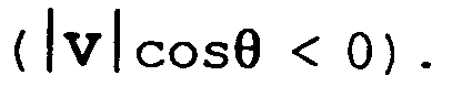
- the relationship between the rotational direction of the bonded substrate stack 30, the fluid ejection direction, and the first operation position (position of the ejection nozzle 112) 401 is determined such that when the velocity of the bonded substrate stack 30 at the position where the fluid ejected from the ejection nozzle 112 is injected is represented by V , and the moving direction of the fluid (jet) is represented by A, the A-direction component of the velocity V (vector) of the bonded substrate stack 30 has a negative value
- This condition will be referred to as a peripheral portion separation condition hereinafter.
- the first operation position 401 is located within a range B shown in Fig. 5.
- the rotational direction of the bonded substrate stack 30, the fluid ejection direction, and the position of the ejection nozzle 112 are controlled such that the peripheral portion separation condition is satisfied. This effectively prevents defects in separation.
- Fig. 6 is a view schematically showing the progress of separation of a bonded substrate stack when peripheral portion separation condition is not satisfied.
- the "separated region” means a region that has already been separated
- the "unseparated region” means a region that has not been separated yet (this also applies to Fig. 7).
- the single-crystal Si layer 13 is peeled off from the insulating layer 14 at the peripheral portion of the bonded substrate stack 30.
- the single-crystal Si layer 13 at the peripheral portion may break. If this phenomenon intermittently occurs as separation progresses, a defective portion (serrate defect) where the single-crystal Si layer 13 breaks in a serrate shape may be generated, as shown in Fig. 6.
- a cause is estimated as follows. When the peripheral portion separation condition is not satisfied, the fluid ejected from the ejection portion 112 always collides against the outermost peripheral portion of the bonded substrate stack 30 to break that portion from the outside.
- the single-crystal Si layer 13 or insulating layer 14 formed on the porous layer 12 often covers the outermost peripheral portion of the bonded substrate stack 30, as shown in Fig. 12.
- the fluid externally injected into the bonded substrate stack 30 does not always easily break both of the single-crystal Si layer 13 and insulating layer 14 at the outermost peripheral portion and reach the porous layer 12.
- the serrate defect is generated probably because the fluid externally injected into the bonded substrate stack 30 breaks the interface between the single-crystal Si layer 13 and the insulating layer 14, and accordingly, the single-crystal Si layer 13 is peeled from the insulating layer 14.
- Fig. 7 is a view schematically showing the progress of separation of a bonded substrate stack when the peripheral portion separation condition is satisfied.
- the rotational direction of the bonded substrate stack is reverse to that of the example shown in Fig. 6.
- the fluid injected into the porous layer 12 inside the outermost peripheral portion of the bonded substrate stack 30 breaks the porous layer 12 at the outermost peripheral portion from the inside to the outside except at the separation start position. Since only the porous layer 12 as the separation layer having the most fragile structure is readily broken, separation does not progress along the interface between the single-crystal Si layer 13 and the insulating layer 14.
- Fig. 8 is a view schematically showing the section of the bonded substrate stack shown in Fig. 7, which is taken along a line S - S'. As is indicated by an arrow in Fig. 8, because of the fluid injected through the already separated portion, pressure acts on the inside of the outermost peripheral portion of the bonded substrate stack 30 to tear the porous layer 12. Separation of the bonded substrate stack 30 progresses not only toward the inside but also toward the outside.
- Bonded substrate stacks each having a porous layer 12 with a two-layered structure in which the upper layer was 4.5 ⁇ m thick and the lower layer 2 ⁇ m thick were separated using an ejection nozzle 112 having a diameter of 0.1 mm.
- the jet pressure was 500 kgf/cm 2 or more, no serrate defects were generated in any samples.
- the jet pressure was set at 400 kgf/cm 2 , some samples had serrate defects. No experiments were conducted for the porous layer 12 with the above condition.
- the jet pressure exceeded, e.g., 1,500 kgf/cm 2 , some substrates cracked by the jet pressure.
- the jet pressure is too high, the substrate may crack.
- a jet having predetermined range of pressure which allows separation of the outermost peripheral portion of a bonded substrate stack from the inside to the outside and does not crack the substrate can be effectively used to prevent any defects.
- this result changes depending on various factors such as the structure of the porous layer including the porosity of the porous layer 12, the number of stacked layered, and the thickness, the thicknesses of the semiconductor substrate 11 and second substrate, the thickness of the single-crystal Si layer 13, the thickness of the insulating layer 14, the jet injection position, and the diameter of the ejection nozzle.
- the arrangement of the separating apparatus 100 will be described again.
- the separating apparatus 100 also has an adjustment mechanism for adjusting the interval between the substrate holding portion 108 and the substrate holding portion 109. Arrangement examples of the adjustment mechanism will be described below.
- Fig. 9 is a view showing the first arrangement example of the adjustment mechanism.
- the adjustment mechanism shown in Fig. 9 uses an air cylinder 122.
- the air cylinder 122 is fixed to, e.g., the support portion 103 and moves the driving source 111 by a piston rod 121.
- the air cylinder 122 is controlled such that the driving source 111 is moved in the direction in which the interval between the substrate holding portion 108 and the substrate holding portion 109 increases (positive direction of the X-axis). In this state, the bonded substrate stack 30 is inserted between the substrate holding portion 108 and the substrate holding portion 109.
- the substrate holding portion 109 presses the bonded substrate stack 30 by the function of the spring 113.
- Fig. 10 is a view showing the second arrangement example of the adjustment mechanism.
- the adjustment mechanism shown in Fig. 10 uses an eccentric cam 131 and motor.
- the eccentric cam 131 is coupled to a motor (not shown) and adjusts the interval between the substrate holding portion 108 and the substrate holding portion 109 by moving a driving plate 132 coupled to the rear end of the motor 111.
- a force in the negative direction of the X-axis acts on the rotating shaft 107 due to the spring 113.
- a gap is formed between the eccentric cam 131 and the driving plate 132.
- a press force acts on the bonded substrate stack 30.
- Another mechanism for adjusting the interval between the substrate holding portion 108 and the substrate holding portion 109 may be arranged on the substrate holding portion 108 side.
- Bonded substrate stack separation processing by the separating apparatus 100 will be described next.
- the bonded substrate stack 30 is conveyed between the substrate holding portion 108 and the substrate holding portion 109 by, e.g., a conveyor robot and held while matching the center of the bonded substrate stack 30 with the center of the substrate holding portions 108 and 109.
- the substrate holding portion 108 vacuum-chucks the bonded substrate stack 30.
- the substrate holding portion 109 is pressed against the bonded substrate stack 30 by the force of the spring 113. More specifically, when the adjustment mechanism shown in Fig. 9 is employed as the adjustment mechanism for adjusting the interval between the substrate holding portion 108 and the substrate holding portion 109, drive of the piston rod 121 by the air cylinder 122 is canceled. When the adjustment mechanism shown in Fig. 10 is employed as the adjustment mechanism, the eccentric cam 131 is rotated such that the press force of the spring 113 acts on the bonded substrate stack 30.
- the vacuum chuck mechanisms 108a and 109a either may or may not vacuum-chuck the bonded substrate stack 30. This is because the bonded substrate stack 30 is held by the press force of the spring 113. However, if the press force is made weak, the bonded substrate stack 30 is preferably vacuum-chucked.
- the rotating shafts 106 and 107 are synchronously rotated by the driving sources 110 and 111.
- the rotational direction is the direction shown in Fig. 5, i.e., the direction in which the peripheral portion separation condition is satisfied in entirely separating the peripheral portion of the bonded substrate stack 30 at the first operation position 401.
- a high-pressure fluid (e.g., water) is fed from the high-pressure pump 115 into the ejection nozzle 112 while controlling pressure by the pressure control section 116.
- the ejection nozzle 112 ejects a high-speed, high-pressure jet.
- the ejection nozzle 112 is moved from the retreat position 403 to the first operation position 401 by the driving robot 450.
- the jet is injected to a portion near the porous layer 12 of the bonded substrate stack 30.
- processing waits until the bonded substrate stack 30 rotates by one or more revolutions, and the peripheral portion of the bonded substrate stack 30 is entirely separated.
- the ejection nozzle 112 is gradually moved to the second operation position 402 by the driving robot 450.
- the second operation position 402 is a position near or passing the position immediately above the center of the bonded substrate stack 30.
- the bonded substrate stack 30 is completely separated into two substrates while the ejection nozzle 112 is moving to the second operation position 402.
- the two substrates separated physically are spaced apart from each other while keeping the jet injected into the bonded substrate stack 30.
- the piston rod 121 is driven in the positive direction of the X-axis (direction in which the spring 113 contracts) by the air cylinder 122 while keeping the substrates vacuum-chucked by the substrate holding portions 108 and 109.
- the eccentric cam 131 is pivoted to drive the rotating shaft 107 in the positive direction of the X-axis (direction in which the spring 113 contracts) while keeping the substrates vacuum-chucked by the substrate holding portions 108 and 109.
- the driving robot 450 moves the ejection nozzle 112 to the standby position 403.
- Ejection of the jet is stopped, and the substrates are detached from the substrate holding portions 108 and 109 by, e.g., a conveyor robot.
- the bonded substrate stack 30 may be separated while changing the jet pressure.
- the reason for this is as follows.
- the jet pressure necessary for separating the bonded substrate stack 30 changes in units of regions of the bonded substrate stack 30.
- the separation force acting on the peripheral portion of the bonded substrate stack 30 is different from that acting on the central portion. That is, the jet pressure necessary for separation changes between the peripheral portion and the central portion. If the bonded substrate stack 30 is separated using predetermined jet pressure, the jet at high pressure is always used during separation processing. In this case, the bonded substrate stack or separated substrates may crack or may be damaged at high probability, resulting in low yield.
- the mechanical strength of the separation region may be decreased.
- the separation region is made too fragile, the separation region readily breaks in bonding two substrates (first and second substrates), cleaning, and other processes. This makes it difficult to manufacture a substrate with a desired quality.
- particles may be generated from the broken separation region and contaminate the manufacturing apparatus and the like.
- Fig. 11 is a graph showing an example of control of jet pressure during separation processing. More specifically, on the basis of the control procedures shown in Fig. 11, the pressure control section 116 controls pressure (jet pressure) generated by the high-pressure pump 115.
- the jet pressure is adjusted in three stages.
- a period T1 the peripheral portion of the bonded substrate stack 30 is separated while keeping the ejection nozzle 112 located at the operation position 401.
- the jet pressure is set to be high because the fluid injected into the bonded substrate stack 30 is readily discharged, and the separation force hardly acts on the bonded substrate stack 30.
- the intermediate portion (to be simply referred to as an intermediate portion hereinafter) between the peripheral portion and the central portion of the bonded substrate stack 30 is separated while moving the ejection nozzle 112 to the second operation position 402.
- the speed of the fluid reduces because it passes through the internal portion of the bonded substrate stack 30.
- the function of separating the bonded substrate stack 30 by the impact of collision of the fluid against the porous layer 12 weakens.
- the intermediate portion has few discharge paths for the fluid injected into the bonded substrate stack 30. For this reason, the separation force due to the pressure of the fluid injected into the bonded substrate stack 30 increases, and the bonded substrate stack 30 is separated mainly by this separation force.
- the central portion of the bonded substrate stack 30 is separated.
- the separated portion comes close to the central portion, the separated portion of the bonded substrate stack 30 warps, and the discharge paths for the fluid increase.
- the pressure of the fluid becomes lower than that during separation of the intermediate portion, and the separation force becomes small.
- the pressure of the fluid is preferably set to be higher than that during separation of the intermediate portion.
- the separating apparatus 100 can be suitably used to separate not only the bonded substrate stack 30 but also a disk-like member having a separation layer. That is, the bonded substrate stack 30 can be regarded as a preferable example of a disk-like member having a separation layer. Disk-like members also include a substrate having an orientation flat or a notch.
- a first p- or n-type single-crystal Si substrate 11 having a resistivity of 0.01 ⁇ cm was anodized in an HF solution in two steps to form a porous layer 12 having a two-layered structure (step shown in Fig. 1A).
- the anodizing conditions were as follows.
- the functions of the two layers of the porous Si layer 12 were separated such that the surface porous Si layer formed first by anodizing using a low current was used to form a high-quality epitaxial Si layer, and the lower porous Si layer formed later by anodizing using a high current (the layer having a higher porosity) was used as a separation layer.
- the thickness of the porous Si layer formed at a low current is not limited to the above thickness (4.5 ⁇ m) but is preferably several hundred to 0.1 ⁇ m.
- the porous Si layer formed at a high current is not limited to the above thickness, either, and only need ensure a thickness that allows separation of the bonded substrate stack at a jet.
- a third and subsequent layers having different porosities may be formed.
- This substrate was oxidized in an oxygen atmosphere at 400°C for 1 hr. With this oxidation, the inner walls of holes in the porous Si layer were covered with thermal oxide films. The surface of this porous Si layer was treated with hydrofluoric acid to remove only the oxide film on the surface of the porous Si layer while leaving the oxide films on the inner walls of the holes. After that, a 0.3- ⁇ m thick single-crystal Si layer 13 was epitaxially grown on the porous Si layer 12 by CVD (Chemical Vapor Deposition). The growth conditions were as follows.
- a 200-nm thick oxide film (SiO 2 layer) 14 was formed on the surface of the epitaxial Si layer 13 by thermal oxidation as an insulating layer (step shown in Fig. 1B).
- a bonded substrate stack 30 formed in the above way was separated by a separating apparatus 100 shown in Fig. 2 (step shown in Fig. 1D). Details will be described later.
- the bonded substrate stack 30 was vertically supported between a substrate holding portion 108 and a substrate holding portion 109.
- the substrate holding portion 109 was pressed against the bonded substrate stack 30 by the force of a spring 113.
- vacuum chuck mechanisms 108a and 109a vacuum-chucked the bonded substrate stack 30 on the substrate holding portions 108 and 109.
- Rotating shafts 106 and 107 were synchronously rotated by driving sources 110 and 111, respectively.
- the rotational direction was set in the direction shown in Fig. 5, i.e., a direction in which the peripheral portion separation condition was satisfied in separating the peripheral portion of the bonded substrate stack 30 at a first operation position 401.
- Jet pressure was set at 500 kgf/cm 2 under the control of a pressure control section 116.
- the ejection nozzle 112 having a diameter of 0.1 mm was used.
- a driving robot 450 moved the ejection nozzle 112 from a retreat position 403 to the first operation position 401.
- the peripheral portion separation condition was satisfied, and in this state, separation of the peripheral portion of the bonded substrate stack 30 started.
- the bonded substrate stack 30 was separated into two substrates without generating any serrate defects and the like at the peripheral portion.
- a number of bonded substrate stacks 30 were separated by the above method, and all bonded substrate stacks had no defects.
- the rotational direction of the bonded substrate stacks 30 was reversed, i.e., the bonded substrate stacks 30 were separated without satisfying the peripheral portion separation condition, some bonded substrate stacks 30 had defects.
- porous Si layer transferred to the second substrate of the two separated substrates was selectively etched using a solution mixture of 49% hydrofluoric acid and 30% hydrogen peroxide while stirring the solution (step shown in Fig. 1E).
- the single-crystal Si layer functioned as an etching stopper layer.
- the porous Si layer was selectively etched and completely removed.
- the etching rate of the above etchant for non-porous Si is very low.
- the selectivity ratio of etching of porous Si to non-porous Si is 10 5 or more.
- the etching amount (about several ten ⁇ ) of the non-porous single-crystal Si layer 13 can be neglected in practical use.
- an SOI substrate having a 0.2- ⁇ m thick single-crystal Si layer 13 on the insulating layer 14 could be formed.
- the film thickness of the single-crystal Si layer 13 after selective etching of the porous Si layer was measured at 100 points on the entire surface.
- the film thickness was 201 nm ⁇ 4 nm.
- Section observation with a transmission electron microscope revealed no new crystal defects in the single-crystal Si layer, indicating that satisfactory crystallinity was maintained.
- the surface roughness was evaluated with an atomic force microscope.
- the mean square roughness in a 50- ⁇ m square area was approximately 0.2 nm. This nearly equals that of a commercially available Si wafer.
- the porous Si layer remaining on the first substrate side was selectively etched using a solution mixture of water, 49% hydrofluoric acid, and 30% hydrogen peroxide while stirring the solution.
- the substrate could be reused as a first or second substrate.
Landscapes
- Mechanical Treatment Of Semiconductor (AREA)
- Element Separation (AREA)
- Recrystallisation Techniques (AREA)
- Container, Conveyance, Adherence, Positioning, Of Wafer (AREA)
Abstract
Description
Claims (21)
- A separating apparatus (100) for separating a disk-like member (30) having a separation layer (12) inside, characterized by comprising:a holding mechanism (108, 109) for holding the disk-like member (30) while rotating the disk-like member about an axis perpendicular to the separation layer (12); anda fluid ejection portion (112) for injecting a stream of fluid into the separation layer (12) of the disk-like member (30) held by said holding portion (108, 109) to separate the disk-like member (30) at the separation layer (12) by the fluid,
wherein when separating a peripheral portion of the disk-like member (30), a rotational direction of the disk-like member (30), a moving direction of the fluid, and a position of said ejection portion (112) are maintained to satisfy a condition in which the moving direction component of the velocity of the peripheral portion of the disk-like member (30) at an injection position of the fluid to the disk-like member (30) has a negative value, assuming the moving direction of the fluid in the positive direction. - The apparatus according to claim 1, characterized in that when separating the peripheral portion of the disk-like member (30), said ejection portion (112) ejects the fluid having pressure at which an outermost peripheral portion of the disk-like member (30) is separated from an inside to an outside by the fluid injected into the disk-like member (30).
- The apparatus according to claim 1, characterized by further comprising a control section (116) for controlling the pressure of the fluid ejected from said ejection portion (112).
- The apparatus according to claim 3, characterized in that said control section (116) changes the pressure of the fluid in accordance with progress of separation processing.
- The apparatus according to any one of claims 1 to 4, characterized by further comprising a driving mechanism (450) for moving said ejection portion (112) along the separation layer (12).
- The apparatus according to claim 5, characterized in that when separating the peripheral portion of the disk-like member (30), said driving mechanism (450) adjusts the position of said ejection portion (112) such that the fluid is injected into the peripheral portion, and when separating a center of the disk-like member (30), said driving mechanism (450) adjusts the position of said ejection portion (112) such that the fluid is injected into the center.
- The apparatus according to any one of claims 1 to 6, characterized in that the separation layer (12) is more fragile than remaining portions of the disk-like member (30).
- The apparatus according to any one of claims 1 to 6, characterized in that the separation layer (12) is a porous layer.
- The apparatus according to any one of claims 1 to 6, characterized in that the separation layer (12) is a porous layer having a multilayered structure.
- A separating apparatus (100) for separating a disk-like member (30) having a separation layer (12) inside, characterized by comprising:a holding portion (108, 109) for holding the disk-like member (30); anda fluid ejection portion (112) for injecting a stream of fluid to the separation layer (12) of the disk-like member (30) held by said holding portion (108, 109) to separate the disk-like member (30) at the separation layer (12) by the fluid,
wherein when separating a peripheral portion of the disk-like member (30), separation processing is executed under a condition in which an outermost peripheral portion of the disk-like member (30) is separated from an inside to an outside of the disk-like member (30) by the fluid injected into the disk-like member (30). - The apparatus according to claim 10, characterized in that said holding portion (108, 109) has a rotation mechanism (110, 111) for holding the disk-like member (30) while rotating the disk-like member (30).
- A separating method of rotating a disk-like member (30) having a separation layer (12) inside about an axis perpendicular to the separation layer (12) and ejecting a stream of fluid from an ejection portion (112) into the separation layer (12) to separate the disk-like member (30) at the separation layer (12) by the fluid, characterized by comprising:the peripheral portion separation step of separating a peripheral portion of the disk-like member (30) when a rotational direction of the disk-like member (30), a moving direction of the fluid, and a position of said ejection portion (112) satisfy a condition in which the moving direction component of the velocity of the disk-like member (30) at an injection position of the fluid to the disk-like member (30) has a negative value.
- The method according to claim 12, characterized in that the peripheral portion separation step comprises ejecting, from said ejection portion (112), the fluid having pressure at which an outermost peripheral portion of the disk-like member (30) is separated from an inside to an outside by the fluid injected into the disk-like member (30).
- The method according to claim 12, characterized by further comprising the control step of controlling the pressure of the fluid ejected from said ejection portion (112).
- The method according to any one of claims 12 to 14, characterized in that the separation layer (12) is more fragile than remaining portions of the disk-like member (30).
- The method according to any one of claims 12 to 14, characterized in that the separation layer (12) is a porous layer.
- The method according to any one of claims 12 to 14, characterized in that the separation layer (12) is a porous layer having a multilayered structure.
- A separating method of holding a disk-like member (30) having a separation layer (12) inside, ejecting a stream of fluid from an ejection portion (112), and injecting the fluid into the separation layer (12) to separate the disk-like member (30) at the separation layer (12) by the fluid, characterized by comprising:the peripheral portion separation step of separating a peripheral portion of the disk-like member (30) under a condition in which an outermost peripheral portion of the disk-like member (30) is separated from an inside to an outside of the disk-like member (30) by the fluid injected into the disk-like member (30).
- The method according to claim 18, characterized in that the peripheral portion separation step comprises executing separation processing while rotating the disk-like member (30) about an axis perpendicular to the separation layer (12).
- A method of manufacturing a semiconductor substrate, characterized by comprising:the step (Fig. 1A, Fig. 1B) of preparing a first substrate (10) having a porous layer (12) inside and a non-porous layer (13, 14) on the porous layer;the step (Fig. 1C) of bonding the first substrate (10) and a second substrate (20) via the non-porous layer (13, 14) to form a bonded substrate stack (30); andthe separation step (Fig. 1D) of separating the bonded substrate stack (30) into two substrates at the porous layer (12) while rotating the bonded substrate stack (30) about an axis perpendicular to the porous layer (12) and ejecting a stream of fluid and injecting the fluid into the porous layer (12),
wherein the separation step (Fig. 1D) comprises the peripheral portion separation step of separating a peripheral portion of the bonded substrate stack (30) when a rotational direction of the bonded substrate stack (30), a moving direction of the fluid, and a position of said ejection portion (112) satisfy a condition in which the moving direction component of the velocity of the bonded substrate stack at an injection position of the fluid to the bonded substrate stack (30) has a negative value. - A method of manufacturing a semiconductor substrate, characterized by comprising:the step (Fig. 1A, Fig. 1B) of preparing a first substrate (10) having a porous layer (12) inside and a non-porous layer (13, 14) on the porous layer;the step of bonding the first substrate (10) and a second substrate (20) via the non-porous layer (13, 14) to form a bonded substrate stack (30); andthe separation step (Fig. 1D) of separating the bonded substrate stack (30) into two substrates at the porous layer (12) while ejecting a stream of fluid and injecting the fluid into the porous layer (12),
wherein the separation step (Fig. 1D) comprises the peripheral portion separation step of separating a peripheral portion of the bonded substrate stack (30) under a condition in which an outermost peripheral portion of the bonded substrate stack (30) is separated from an inside to an outside of the bonded substrate stack (30) by the fluid injected into the bonded substrate stack (30).
Applications Claiming Priority (2)
| Application Number | Priority Date | Filing Date | Title |
|---|---|---|---|
| JP2548299 | 1999-02-02 | ||
| JP02548299A JP4365920B2 (en) | 1999-02-02 | 1999-02-02 | Separation method and semiconductor substrate manufacturing method |
Publications (2)
| Publication Number | Publication Date |
|---|---|
| EP1026727A2 true EP1026727A2 (en) | 2000-08-09 |
| EP1026727A3 EP1026727A3 (en) | 2005-01-19 |
Family
ID=12167282
Family Applications (1)
| Application Number | Title | Priority Date | Filing Date |
|---|---|---|---|
| EP00300718A Withdrawn EP1026727A3 (en) | 1999-02-02 | 2000-01-31 | Separating apparatus, separating method, and method of manufacturing semiconductor substrate |
Country Status (6)
| Country | Link |
|---|---|
| US (2) | US6609446B1 (en) |
| EP (1) | EP1026727A3 (en) |
| JP (1) | JP4365920B2 (en) |
| KR (1) | KR100370914B1 (en) |
| CN (1) | CN1264920A (en) |
| TW (1) | TW495874B (en) |
Cited By (2)
| Publication number | Priority date | Publication date | Assignee | Title |
|---|---|---|---|---|
| US6707061B2 (en) | 2000-10-26 | 2004-03-16 | Matsushita Electric Works, Ltd. | Field emission type electron source |
| EP1197987A3 (en) * | 2000-08-25 | 2005-08-17 | Canon Kabushiki Kaisha | Method and apparatus for separating sample |
Families Citing this family (30)
| Publication number | Priority date | Publication date | Assignee | Title |
|---|---|---|---|---|
| US6969635B2 (en) * | 2000-12-07 | 2005-11-29 | Reflectivity, Inc. | Methods for depositing, releasing and packaging micro-electromechanical devices on wafer substrates |
| SG68035A1 (en) * | 1997-03-27 | 1999-10-19 | Canon Kk | Method and apparatus for separating composite member using fluid |
| JP2003017668A (en) * | 2001-06-29 | 2003-01-17 | Canon Inc | Member separating method and separating device |
| WO2003030228A2 (en) * | 2001-10-03 | 2003-04-10 | Silicon Valley Group, Inc. | Method and apparatus for mitigating cross-contamination between liquid dispensing jets in close proximity to a surface |
| US7105448B2 (en) * | 2003-02-28 | 2006-09-12 | Semiconductor Energy Laboratory Co., Ltd. | Method for peeling off semiconductor element and method for manufacturing semiconductor device |
| US7538010B2 (en) * | 2003-07-24 | 2009-05-26 | S.O.I.Tec Silicon On Insulator Technologies | Method of fabricating an epitaxially grown layer |
| FR2857983B1 (en) * | 2003-07-24 | 2005-09-02 | Soitec Silicon On Insulator | PROCESS FOR PRODUCING AN EPITAXIC LAYER |
| FR2860842B1 (en) * | 2003-10-14 | 2007-11-02 | Tracit Technologies | PROCESS FOR PREPARING AND ASSEMBLING SUBSTRATES |
| JP2005136214A (en) * | 2003-10-30 | 2005-05-26 | Nec Corp | Method for manufacturing thin film device substrate |
| FR2880184B1 (en) * | 2004-12-28 | 2007-03-30 | Commissariat Energie Atomique | METHOD OF SORTING A STRUCTURE OBTAINED BY ASSEMBLING TWO PLATES |
| US7071047B1 (en) * | 2005-01-28 | 2006-07-04 | International Business Machines Corporation | Method of forming buried isolation regions in semiconductor substrates and semiconductor devices with buried isolation regions |
| JP4389867B2 (en) | 2005-12-14 | 2009-12-24 | トヨタ自動車株式会社 | Control device for internal combustion engine |
| JP5457216B2 (en) * | 2009-02-27 | 2014-04-02 | キヤノンアネルバ株式会社 | Substrate support apparatus, substrate transfer apparatus, and electrical device manufacturing method |
| DE102011053772B3 (en) * | 2011-09-20 | 2013-02-21 | Optotech Optikmaschinen Gmbh | Method and device for processing a plastic part with a lathe device |
| JP2013219328A (en) * | 2012-03-13 | 2013-10-24 | Tokyo Electron Ltd | Peeling device, peeling system, peeling method, program, and computer storage medium |
| JP6101084B2 (en) * | 2013-01-17 | 2017-03-22 | 株式会社ディスコ | Separation device |
| CN103280423A (en) * | 2013-05-29 | 2013-09-04 | 华进半导体封装先导技术研发中心有限公司 | Technology and system for mechanical bonding disassembling |
| JP6301137B2 (en) * | 2014-01-22 | 2018-03-28 | 株式会社ディスコ | Separation device |
| KR20160125585A (en) * | 2015-04-21 | 2016-11-01 | 삼성전자주식회사 | Substrate treating apparatus and substrate treating method |
| JP6991673B2 (en) | 2018-02-27 | 2022-01-12 | 株式会社ディスコ | Peeling method |
| US11245134B2 (en) | 2019-01-02 | 2022-02-08 | International Business Machines Corporation | Lithium energy storage device with composite anode |
| US11961958B2 (en) | 2019-05-27 | 2024-04-16 | International Business Machines Corporation | 3D textured composite silicon anode and fluorinated lithium compound electrochemical cell |
| KR102204732B1 (en) * | 2019-11-11 | 2021-01-19 | (주)더숨 | Producing method of silicon on insulator substrate |
| US11322787B2 (en) | 2019-11-18 | 2022-05-03 | International Business Machines Corporation | Encapsulating in-situ energy storage device with cathode contact |
| KR102267955B1 (en) * | 2019-11-26 | 2021-06-22 | 세메스 주식회사 | Wafer debonding apparatus |
| US11876233B2 (en) | 2020-02-20 | 2024-01-16 | International Business Machines Corporation | Thin film battery stacking |
| US12347831B2 (en) | 2020-06-22 | 2025-07-01 | International Business Machines Corporation | Energy storage method using aluminum oxide protected lithium metal tunable 3D silicon batteries |
| US12406980B2 (en) | 2020-06-22 | 2025-09-02 | International Business Machines Corporation | Aluminum oxide protected lithium metal tunable 3D silicon batteries |
| US11721801B2 (en) | 2020-08-17 | 2023-08-08 | International Business Machines Corporation, Armonk | Low resistance composite silicon-based electrode |
| US12567583B2 (en) | 2021-01-11 | 2026-03-03 | Devendra K. Sadana | Lithium ion battery with thin anode |
Family Cites Families (17)
| Publication number | Priority date | Publication date | Assignee | Title |
|---|---|---|---|---|
| US3969813A (en) * | 1975-08-15 | 1976-07-20 | Bell Telephone Laboratories, Incorporated | Method and apparatus for removal of semiconductor chips from hybrid circuits |
| JPS52121883A (en) * | 1976-04-06 | 1977-10-13 | Toshiba Corp | Jet cutting method |
| US4466852A (en) * | 1983-10-27 | 1984-08-21 | At&T Technologies, Inc. | Method and apparatus for demounting wafers |
| JP2608351B2 (en) | 1990-08-03 | 1997-05-07 | キヤノン株式会社 | Semiconductor member and method of manufacturing semiconductor member |
| CA2090371A1 (en) * | 1992-03-27 | 1993-09-28 | William Frank Banholzer | Water jet mixing tubes used in water jet cutting devices and method of preparation thereof |
| JP3257580B2 (en) | 1994-03-10 | 2002-02-18 | キヤノン株式会社 | Manufacturing method of semiconductor substrate |
| SG79917A1 (en) * | 1995-04-26 | 2001-04-17 | Canon Kk | Liquid ejecting method with movable member |
| KR0165467B1 (en) * | 1995-10-31 | 1999-02-01 | 김광호 | Wafer Debonder and Wafer Debonding Method Using the Same |
| FR2752332B1 (en) * | 1996-08-12 | 1998-09-11 | Commissariat Energie Atomique | DEVICE FOR PICKING UP WAFERS AND METHOD FOR IMPLEMENTING THE DEVICE |
| SG68035A1 (en) * | 1997-03-27 | 1999-10-19 | Canon Kk | Method and apparatus for separating composite member using fluid |
| JP2877800B2 (en) | 1997-03-27 | 1999-03-31 | キヤノン株式会社 | Method of separating composite member, separated member, separation device, method of manufacturing semiconductor substrate, and semiconductor substrate |
| AU7685198A (en) * | 1997-05-12 | 1998-12-08 | Silicon Genesis Corporation | A controlled cleavage process |
| US6159824A (en) * | 1997-05-12 | 2000-12-12 | Silicon Genesis Corporation | Silicon-on-silicon wafer bonding process using a thin film blister-separation method |
| JPH115064A (en) * | 1997-06-16 | 1999-01-12 | Canon Inc | Sample separation apparatus and method, and substrate manufacturing method |
| US6153524A (en) * | 1997-07-29 | 2000-11-28 | Silicon Genesis Corporation | Cluster tool method using plasma immersion ion implantation |
| JP2000164905A (en) * | 1998-09-22 | 2000-06-16 | Canon Inc | Method of manufacturing photoelectric conversion device and device for manufacturing the same |
| JP2000223683A (en) * | 1999-02-02 | 2000-08-11 | Canon Inc | Composite member and its separation method, bonded substrate and its separation method, transfer layer transfer method, and SOI substrate manufacturing method |
-
1999
- 1999-02-02 JP JP02548299A patent/JP4365920B2/en not_active Expired - Fee Related
-
2000
- 2000-01-31 EP EP00300718A patent/EP1026727A3/en not_active Withdrawn
- 2000-01-31 TW TW089101653A patent/TW495874B/en not_active IP Right Cessation
- 2000-02-01 US US09/495,847 patent/US6609446B1/en not_active Expired - Fee Related
- 2000-02-02 KR KR10-2000-0005287A patent/KR100370914B1/en not_active Expired - Fee Related
- 2000-02-02 CN CN00101846A patent/CN1264920A/en active Pending
-
2003
- 2003-06-25 US US10/602,922 patent/US6900114B2/en not_active Expired - Fee Related
Cited By (2)
| Publication number | Priority date | Publication date | Assignee | Title |
|---|---|---|---|---|
| EP1197987A3 (en) * | 2000-08-25 | 2005-08-17 | Canon Kabushiki Kaisha | Method and apparatus for separating sample |
| US6707061B2 (en) | 2000-10-26 | 2004-03-16 | Matsushita Electric Works, Ltd. | Field emission type electron source |
Also Published As
| Publication number | Publication date |
|---|---|
| US6900114B2 (en) | 2005-05-31 |
| US20040082146A1 (en) | 2004-04-29 |
| TW495874B (en) | 2002-07-21 |
| JP2000223383A (en) | 2000-08-11 |
| CN1264920A (en) | 2000-08-30 |
| KR20000057895A (en) | 2000-09-25 |
| KR100370914B1 (en) | 2003-02-05 |
| EP1026727A3 (en) | 2005-01-19 |
| JP4365920B2 (en) | 2009-11-18 |
| US6609446B1 (en) | 2003-08-26 |
Similar Documents
| Publication | Publication Date | Title |
|---|---|---|
| US6900114B2 (en) | Separating apparatus, separating method, and method of manufacturing semiconductor substrate | |
| EP0925887B1 (en) | Object separating method, and method of manufacturing semiconductor substrate | |
| US6521078B2 (en) | Sample separating apparatus and method, and substrate manufacturing method | |
| US6653205B2 (en) | Composite member separating method, thin film manufacturing method, and composite member separating apparatus | |
| US6376332B1 (en) | Composite member and separating method therefor, bonded substrate stack and separating method therefor, transfer method for transfer layer, and SOI substrate manufacturing method | |
| KR100351024B1 (en) | Composite member, its separation method, and preparation method of semiconductor substrate by utilization thereof | |
| US6427747B1 (en) | Apparatus and method of separating sample and substrate fabrication method | |
| US6825099B2 (en) | Method and apparatus for separating member | |
| US6852187B2 (en) | Method and apparatus for separating member | |
| US6540861B2 (en) | Member separating apparatus and processing apparatus | |
| JPH11195570A (en) | Apparatus and method for separating objects and method for manufacturing semiconductor substrate | |
| JPH11243040A (en) | Sample separation apparatus, sample separation method, and substrate manufacturing method |
Legal Events
| Date | Code | Title | Description |
|---|---|---|---|
| PUAI | Public reference made under article 153(3) epc to a published international application that has entered the european phase |
Free format text: ORIGINAL CODE: 0009012 |
|
| AK | Designated contracting states |
Kind code of ref document: A2 Designated state(s): AT BE CH CY DE DK ES FI FR GB GR IE IT LI LU MC NL PT SE |
|
| AX | Request for extension of the european patent |
Free format text: AL;LT;LV;MK;RO;SI |
|
| PUAL | Search report despatched |
Free format text: ORIGINAL CODE: 0009013 |
|
| AK | Designated contracting states |
Kind code of ref document: A3 Designated state(s): AT BE CH CY DE DK ES FI FR GB GR IE IT LI LU MC NL PT SE |
|
| AX | Request for extension of the european patent |
Extension state: AL LT LV MK RO SI |
|
| RIC1 | Information provided on ipc code assigned before grant |
Ipc: 7H 01L 21/762 B Ipc: 7H 01L 21/00 A |
|
| 17P | Request for examination filed |
Effective date: 20050701 |
|
| AKX | Designation fees paid |
Designated state(s): DE FR GB IT |
|
| STAA | Information on the status of an ep patent application or granted ep patent |
Free format text: STATUS: THE APPLICATION HAS BEEN WITHDRAWN |
|
| 18W | Application withdrawn |
Effective date: 20051216 |