EP1026599A2 - Druckerschnittstellengerät, Steuerverfahren dafür und Datenspeichermedium - Google Patents
Druckerschnittstellengerät, Steuerverfahren dafür und Datenspeichermedium Download PDFInfo
- Publication number
- EP1026599A2 EP1026599A2 EP00102166A EP00102166A EP1026599A2 EP 1026599 A2 EP1026599 A2 EP 1026599A2 EP 00102166 A EP00102166 A EP 00102166A EP 00102166 A EP00102166 A EP 00102166A EP 1026599 A2 EP1026599 A2 EP 1026599A2
- Authority
- EP
- European Patent Office
- Prior art keywords
- printer
- data
- real
- command data
- interface device
- Prior art date
- Legal status (The legal status is an assumption and is not a legal conclusion. Google has not performed a legal analysis and makes no representation as to the accuracy of the status listed.)
- Granted
Links
Images


Classifications
-
- H—ELECTRICITY
- H02—GENERATION; CONVERSION OR DISTRIBUTION OF ELECTRIC POWER
- H02K—DYNAMO-ELECTRIC MACHINES
- H02K1/00—Details of the magnetic circuit
- H02K1/06—Details of the magnetic circuit characterised by the shape, form or construction
- H02K1/22—Rotating parts of the magnetic circuit
- H02K1/28—Means for mounting or fastening rotating magnetic parts on to, or to, the rotor structures
-
- G—PHYSICS
- G06—COMPUTING OR CALCULATING; COUNTING
- G06F—ELECTRIC DIGITAL DATA PROCESSING
- G06F3/00—Input arrangements for transferring data to be processed into a form capable of being handled by the computer; Output arrangements for transferring data from processing unit to output unit, e.g. interface arrangements
- G06F3/12—Digital output to print unit, e.g. line printer, chain printer
- G06F3/1201—Dedicated interfaces to print systems
- G06F3/1202—Dedicated interfaces to print systems specifically adapted to achieve a particular effect
- G06F3/1211—Improving printing performance
-
- F—MECHANICAL ENGINEERING; LIGHTING; HEATING; WEAPONS; BLASTING
- F16—ENGINEERING ELEMENTS AND UNITS; GENERAL MEASURES FOR PRODUCING AND MAINTAINING EFFECTIVE FUNCTIONING OF MACHINES OR INSTALLATIONS; THERMAL INSULATION IN GENERAL
- F16C—SHAFTS; FLEXIBLE SHAFTS; ELEMENTS OR CRANKSHAFT MECHANISMS; ROTARY BODIES OTHER THAN GEARING ELEMENTS; BEARINGS
- F16C33/00—Parts of bearings; Special methods for making bearings or parts thereof
- F16C33/02—Parts of sliding-contact bearings
- F16C33/04—Brasses; Bushes; Linings
- F16C33/06—Sliding surface mainly made of metal
- F16C33/10—Construction relative to lubrication
-
- G—PHYSICS
- G06—COMPUTING OR CALCULATING; COUNTING
- G06F—ELECTRIC DIGITAL DATA PROCESSING
- G06F3/00—Input arrangements for transferring data to be processed into a form capable of being handled by the computer; Output arrangements for transferring data from processing unit to output unit, e.g. interface arrangements
- G06F3/12—Digital output to print unit, e.g. line printer, chain printer
- G06F3/1201—Dedicated interfaces to print systems
- G06F3/1223—Dedicated interfaces to print systems specifically adapted to use a particular technique
- G06F3/1236—Connection management
-
- G—PHYSICS
- G06—COMPUTING OR CALCULATING; COUNTING
- G06F—ELECTRIC DIGITAL DATA PROCESSING
- G06F3/00—Input arrangements for transferring data to be processed into a form capable of being handled by the computer; Output arrangements for transferring data from processing unit to output unit, e.g. interface arrangements
- G06F3/12—Digital output to print unit, e.g. line printer, chain printer
- G06F3/1201—Dedicated interfaces to print systems
- G06F3/1278—Dedicated interfaces to print systems specifically adapted to adopt a particular infrastructure
- G06F3/1284—Local printer device
-
- G—PHYSICS
- G06—COMPUTING OR CALCULATING; COUNTING
- G06K—GRAPHICAL DATA READING; PRESENTATION OF DATA; RECORD CARRIERS; HANDLING RECORD CARRIERS
- G06K15/00—Arrangements for producing a permanent visual presentation of the output data, e.g. computer output printers
- G06K15/02—Arrangements for producing a permanent visual presentation of the output data, e.g. computer output printers using printers
- G06K15/18—Conditioning data for presenting it to the physical printing elements
- G06K15/1801—Input data handling means
- G06K15/1803—Receiving particular commands
-
- H—ELECTRICITY
- H02—GENERATION; CONVERSION OR DISTRIBUTION OF ELECTRIC POWER
- H02K—DYNAMO-ELECTRIC MACHINES
- H02K17/00—Asynchronous induction motors; Asynchronous induction generators
- H02K17/02—Asynchronous induction motors
-
- H—ELECTRICITY
- H02—GENERATION; CONVERSION OR DISTRIBUTION OF ELECTRIC POWER
- H02K—DYNAMO-ELECTRIC MACHINES
- H02K5/00—Casings; Enclosures; Supports
- H02K5/04—Casings or enclosures characterised by the shape, form or construction thereof
- H02K5/16—Means for supporting bearings, e.g. insulating supports or means for fitting bearings in the bearing-shields
-
- H—ELECTRICITY
- H02—GENERATION; CONVERSION OR DISTRIBUTION OF ELECTRIC POWER
- H02K—DYNAMO-ELECTRIC MACHINES
- H02K5/00—Casings; Enclosures; Supports
- H02K5/24—Casings; Enclosures; Supports specially adapted for suppression or reduction of noise or vibrations
Definitions
- the present invention relates to an interface device adapted to be detachably mounted in a printer for connecting the printer to a host computer so as to allow exchange of data between the two.
- the present invention further relates to a method of controlling the interface device.
- a common interface uses the host computer's parallel port, another one the serial or RS-232 port, and yet others an IEEE (Institute of Electrical and Electronic Engineers) 1284 port. More recent interfaces use the USB (Universal Serial Bus) standard or a communications network to which the host computer is connected.
- USB Universal Serial Bus
- Command data sent by the host computer through such an interface to a printer is a byte stream of command data representing print commands and control commands.
- the print commands instruct the printer to print text or graphics, while the control commands invoke processes for controlling the printer.
- the printer hardware While the shape and the design of the physical connector for connecting the interface to the host computer typically differ according to the interface standard, it is desirable for the printer hardware to be independent of the way it is connected to the host computer. More specifically, while users may replace the host computer, they commonly want to continue using the same printer.
- the interface device when the host computer sends command data to the interface device, the interface device sends the received command data to the printer in the sequence received.
- the printer then stores the command data in a receive buffer.
- the printer notifies the host computer via the interface device when the receive buffer of the printer becomes full by sending an appropriate signal to the host computer via a busy signal line or by using an Auto Status Back (ASB) function as taught in EP-A-0 654 757.
- ASB Auto Status Back
- Another object of the invention is to provide a control method for controlling the interface device and a storage medium carrying the method in the form of a computer program.
- An interface device thus comprised can recognize real-time commands and send them to the printer even when the printer cannot receive data because, for example, the printer's receive buffer is full or the printer is off-line because its cover is open.
- the interface device preferably stores the received command data in an internal memory.
- the second interface means of the interface device according to the present invention can have a connector conforming to the RS-232 standard.
- the interface device according to the present invention can be designed to have a size that will fit within the printer's housing when it is installed in an expansion slot of the printer.
- the interface device can be designed so that when the command transmission controller causes the second interface means to send real-time command data to the printer, this data is not stored in memory.
- the interface device can be designed so that when data sent by the second interface means is interrupted in the middle of a data sequence of a non-real-time command, the command transmission controller causes the real-time command data to be sent after transmission of this interrupted data sequence has been completed. It is therefore possible to prevent real-time command data from interrupting transmission of a non-real-time command data sequence. This is achieved by the interface device detecting whether a non-real-time command is currently being transmitted, and delaying transmission of real-time command data until transmission of the non-real-time command has been completed, that is, until there is a break between commands.
- a program for controlling the interface device according to the present invention can be stored in machine-readable form on various types of storage medium such as a Compact Disc (CD), a floppy disk, a hard disk, a magneto-optical disk, a Digital Video Disk (DVD), a magnetic tape and a semiconductor memory.
- CD Compact Disc
- floppy disk a floppy disk
- hard disk a magneto-optical disk
- DVD Digital Video Disk
- magnetic tape a magnetic tape
- semiconductor memory a semiconductor memory
- such program can be loaded into a server computer for the World Wide Web (WWW) so that users can download the program from the server and save the program in a local interface device to update the interface device control program so that the program according to the present invention is run by the interface device.
- WWW World Wide Web
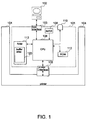
- Fig. 1 is a block diagram of an exemplary basic structure of an interface device according to the present invention.
- the interface device 101 is connected to a host computer 102 by way of host interface 103 so as to exchange data with the host computer, mainly to receive command data from the host computer 102.
- the interface device 101 is further connected by way of printer interface 105 to printer 104 so as to exchange data with the printer, for instance, to send the command data received from the host computer 102 to the printer.
- printer interface 105 to printer 104 so as to exchange data with the printer, for instance, to send the command data received from the host computer 102 to the printer.
- the printer 104 Based on the print commands among the received command data, the printer 104 prints text and images on a printing medium such as paper, film, etc..
- Various printer operations and settings are controlled by means of various control commands contained in the received command data.
- the host interface 103 and the printer interface 105 can be compatible with various standards and protocols to enable, for example, serial data transmission conforming to the RS-232 standard, parallel data transmission conforming to the Centronics standard, network data exchange via an Ethernet 10Base-T, 100Base-T, or other networking protocol, or data transmission using the new USB or other new data transmission standard.
- Signal level conversions can be easily accommodated by providing a driver circuit for level conversions appropriate to the host interface 103 or printer interface 105 when the TTL (transistor-transistor logic) circuit drive voltage of the host computer 102 or printer 104 differs from the internal drive voltage of the interface device 101.
- the physical connectors of the host interface 103 and/or the printer interface 105 are preferably those of an existing standard.
- the printer interface 105 notifies the interface device 101 whether the printer is ready to receive data (referred to RRD state hereinafter) or is not in an RRD state, for instance, because the receive buffer of the printer 104 is full.
- the CPU (central processing unit) 106 can therefore determine whether data can be sent to the printer 104 by monitoring the printer interface 105. This detection is possible using the ASB function of the printer 104, or by detecting the state of the busy signal line if the printer interface 105 has a busy signal line.
- the CPU 106 also monitors the host interface 103 and, if data is received, detects whether data can be sent to the printer 104. If data cannot be sent to the printer 104, the CPU 106 buffers the data until it can be sent. It should be noted that prior art interface devices do not have a buffering capability.
- a buffer area 120 reserved in RAM (random access memory) 113 is used for buffering command data.
- RAM 113 is also used for temporarily storing other data.
- the CPU 106 itself operates in accordance with a program stored in ROM (read only memory) 112.
- ROM read only memory
- the CPU 106 reads this program from ROM 112 and begins to run the program to control interface device 101.
- This program or BIOS (Basic Input Output System) stored in ROM 112 is preferably implemented in a manner such that it can be updated through the host computer 102.
- BIOS Basic Input Output System
- BIOS Basic Input Output System
- BIOS Basic Input Output System
- ROM 112 is preferably implemented in a manner such that it can be updated through the host computer 102.
- a Compact Disc (CD), floppy disk, magneto-optical disk, hard disk, Digital Video Disc (DVD), magnetic tape, semiconductor memory, or other storage medium that can be read by host computer 102 can be employed to hold the program to be executed by the CPU 106.
- the CPU 106 detects the setting of a DIP switch 108 to set, for example, the data length, parity check, transmission rate, and other parameter settings used by the host interface 103 and printer interface 105 for communication with the host computer and the printer, respectively.
- the operating indicator 110 indicates that the interface device is working.
- the communications status of host interface 103 and printer interface 105, and the processing status of the CPU 106 can be indicated by, for example, changing the indicator color or flashing state.
- host interface 103 printer interface 105, operating indicator 110, ROM 112, and RAM 113 are described here as being directly connected to the CPU 106, these components can alternatively be connected indirectly to the CPU 106 by way of a bus.
- Fig. 2 is a perspective view of an exemplary interface device according to the present invention.
- the host interface 103 (of which only the connector is shown) and the operating indicator 110 for the interface device 101 are disposed at the back, or outside, of the interface device 101.
- the interface device 101 is typically designed to have a size that fits completely into the expansion slot of the printer 104.
- An interface device designed in this manner is also called a printer expansion module or card.
- the host interface 103 and operating indicator 110 appear to be disposed in the back of the printer 104 when the interface device 101 is installed in the printer 104. Furthermore, designing the interface device 101 to allow installation in an expansion slot of the printer 104 also protects the interface device 101 from accidental contact and impact. This type of interface device 101 design yet further helps to improve printer appearance and thus the aesthetics of an office in which the printer is used.
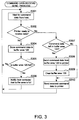
- the CPU 106 first simply waits in a standby made for command data from the host computer 102 to arrive at the host interface 103 (step S301).
- the CPU 106 can operate in a co-routine processing mode in which control can be shifted to other processes during this standby mode.
- the host interface 103 generates a receive interrupt to alert the CPU 106 when command data arrive so that the CPU 106 leaves the standby mode and continues with the rest of the procedure.
- the CPU 106 checks whether the printer 104 is an RRD state (step S302). As noted above, the CPU 106 can detect whether the printer 104 is in an RRD state directly by detecting the state of a busy signal line, or indirectly by detecting the status value sent by the printers ASB function and stored in RAM 113.
- step S301 If the printer is not in an RRD state at this time (step S302 returns No ), the data received in step S301 is stored in buffer area 120 in RAM 113 (step S304).
- the buffer area 120 is typically organized as a FIFO (first in, first out) type queuing buffer, and can thus be achieved using a ring buffer or similar technique.
- step S305 After received command data is stored in the buffer area 120, it is determined in step S305 whether buffer area 120 is full. If it is (step S305 returns Yes ), the host computer 102 is notified that the buffer is full (step S306), and the procedure loops back to step S301. It should be noted that this can be accomplished based on a protocol similar to that of the ASB function, or using the busy signal line if the host interface 103 is provided with a busy signal line.
- step S305 returns No
- the procedure loops back to step S301.
- the host computer 102 can be notified that the buffer is not full before the procedure loops back to step S301.
- step S302 the printer is ready to receive data
- the CPU 106 detects whether there is any command data in the buffer area 120 (step S307). If there is (step S307 returns Yes ), the buffered command data is sent to the printer 104 by way of printer interface 105 (step S308). The buffer area 120 is then cleared (step S309), after which the command data received in step S301 is sent to the printer 104 (step S310), and the procedure loops back to step S301.
- step S307 If there is no command data in the buffer area 120 (step S307 returns No ), the procedure advances to step S310.
- the printer's receive buffer becomes full while the buffered command data is being sent from the buffer area 120 in step S308, the data received in step S301 can be grouped with any data remaining in the buffer area 120 to a new block of buffered data.
- the host interface 103 was an RS-232 standard interface.
- the printer interface 105 was a clock synchronized serial interface designed for half duplex communication.
- the printer interface 105 performed any conversion required for communication with the host, and operated at a communications speed of 1.25 Mbps.
- a 40 byte buffer area was reserved in RAM 113 for data buffering.
- the maximum communications rate is 38,400 bps.
- the communications rate was improved to 115 kbps to 230 kbps, that is, the maximum data transfer rate used by today's most commonly available personal computers. Further experiments also demonstrated that communication at an even higher data transfer rate is also possible.
- command data received from the host computer includes both normal commands and real-time commands.
- a real-time command needs to be sent to the printer immediately.
- This first embodiment of the present invention is therefore based on the above-described basic structure, but differs in that a particular command transmission controller is achieved by means of the host interface 103 in conjunction with CPU 106, and that data is also transmitted to the host computer.
- the interface device 101 detects whether the host interface 103 in a data receiving state (step S401).
- step S401 If the host interface 103 is not in a data receiving state (step S401 returns No ), the interface device 101 checks whether the printer 104 is in the RRD state, i.e., whether data from the host can be sent to the printer by way of printer interface 105 (step S402). If the printer is in the RRD state (step S402 returns Yes ), a data send process for sending received data through the printer interface 105 to the printer (step S403) is performed, and this process ends. However, if the printer is not in the RRD state (step S402 returns No ), the procedure loops back to step S401.
- step S404 the interface device 101 checks whether the printer 104 is in the RRD state (step S404). If yes (step S404 returns Yes ), the interface device 101 checks whether previously received data is still in the buffer area of the RAM 113 (step S405). If there is (step S405 returns Yes ), the buffered data is transferred to the printer 104 first (step S406), and then the data newly received by the host interface 103 is transferred to the printer 104 (step S407), and this process ends. If there is no previously received data left in the buffer area of the RAM 113 (step S405 returns No ), the procedure advances to step S407.
- step S404 If the printer 104 is not in the RRD state (step S404 returns No ), the interface device 101 receives the data (step S408).
- step S409 It is next determined whether there are any real-time command data in the received data (step S409). If no (step S409 returns No ), the received data is accumulated in the buffer area 120 (step S411). If there is a real-time command (step S409 returns Yes ), it is sent to the printer (step S410), and is also accumulated in the buffer area of RAM 113 (step S411).
- step S412 It is then determined whether there is still data to receive (step S412). If there is no further data to receive (step S412 returns No ), the process ends. If there is further data to receive (step S412 returns Yes ), the procedure loops back to step S409.
- step S411 a process can be performed in step S411 for detecting whether the buffer area 120 is full, and if it is, for notifying the host computer. Furthermore, data is accumulated in the buffer area of RAM 113 in step S411 whether or not the received data is a real-time command. However, because real-time commands have already been sent to the printer 104, it is alternatively possible to not accumulate any real-time commands in the buffer area 120.
- the interface device 101 of the first embodiment of the invention sends real-time commands contained in data received via the host interface device 103 immediately to the printer 104.
- real-time command data may interrupt normal command data transmission when non-real time commands, referred to herein as "normal commands" are data streams of more than a single byte.
- the printer 104 uses a command system that allows real-time commands and normal commands to be distinguished from one another. This can be achieved, for example, by transmitting data in byte units (8 bit units) where the highest bit is always set (i.e., has a value of 1) to indicate a real-time command, and is always cleared (i.e., set to 0) to indicate a normal command.
- the first embodiment does not, however, allow for compatibility with all existing command systems. This is because unexpected operations can occur when a real-time command interrupts a normal command data stream in existing command systems.
- This second embodiment of the present invention allows to correctly interpret received commands even in such cases.
- interface device 101 When a data stream such as that described above is sent from the host computer 102, interface device 101 according to the second embodiment functions so that the printer 104 receives a data stream as shown below:
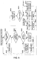
- step S501 the interface device 101 checks whether the host interface 103 is in a data receiving state (step S501). If not (step S501 returns No ), it enters a standby mode (step S502) and then the procedure loops back to step S501.
- step S501 returns No
- step S502 a 1-byte send process described below can be activated by an interrupt during the standby mode of step S502.
- This 1-byte send process is activated when the printer 104 enters the RRD state, e.g., because there is free space in the printer's receive buffer. This 1-byte send process can be repeatedly activated during this standby mode.
- step S501 If the host interface 103 is in a data receiving state (step S501 returns Yes ), the interface device 101 checks whether space is available in the buffer area 120 (step S504). If not (step S504 returns No ), it checks whether the printer 104 is in the RRD state (step S505). If the printer 104 is not in the RRD state (step S505 returns No ), it so notifies the host computer 102 (step S506), enters a standby mode (step S507), and then the procedure loops back to step S504. It should be noted that the 1-byte send process described below can be activated by an interrupt during the standby mode of step S507. This 1-byte send process can be repeatedly activated during this standby mode.
- step S505 If the printer 104 is in the RRD state (step S505 returns Yes ), the 1-byte send process described below is run (step S508), and the procedure loops back to step S504.
- Step S510 detects whether the received data is one of the following types (step S510):
- a first flag area comprising one flag bit for each byte of the buffer area 120 is also reserved in RAM 113. If the received data byte is a normal command byte other than the last byte (step S510, non-last normal command byte), the byte is added to the receive buffer (step S511), and the corresponding flag bit in the first flag area is cleared to 0 (step S512); then the procedure loops back to step S501. If the received data byte is the last byte of a normal command (step S510, last byte), the byte is also added to the receive buffer (step S513), but the corresponding flag bit in the first flag area is set to 1 in this case (step S514), before the procedure loops back to step S501.
- a flag bit in the first flag area When a flag bit in the first flag area is set to 1, it means that a real-time command may be transmitted to the printer immediately after the byte corresponding to that flag bit has been sent.
- step S510 If a received data byte is the first byte in a real-time command (step S510, RTC byte 1),the real-time command receive/send process described below is performed (step S515), and the procedure loops back to step S501.
- Fig. 6 is a flow chart of 1-byte send process in this second embodiment. As noted above, this 1-byte send process is executed when no space is available in the buffer area 120 of interface device 101, and/or when space becomes available in the receive buffer of the printer 104.
- the first step is to detect whether the printer 104 is in the RRD state (step S601). If not (step S601 returns No ), control returns to the calling process. If the printer 104 is in the RRD state (step S601 returns Yes ), 1 byte is read from buffer area 120 (step S602), and is sent to the printer 104 (step S603). The space available in the buffer area 120 thus increases by 1 byte. The value of the flag bit in the first flag area corresponding to the byte just sent is stored as an insertion flag in a second flag area also reserved in RAM 113 (step S604). This means that whether the byte last transmitted by step S603 was the last byte of a command stream is stored in this second flag area of RAM 113. Once this value is stored, the 1-byte send process returns to the calling process.
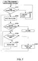
- Fig. 7 is a flow chart of real-time command receive/send process in the second embodiment.
- the first step in this process is to check the value of the insertion flag (step S701). If the flag is set to 1, that is, if a real-time command can be inserted (step S701 returns 1), the real-time command byte is sent to the printer 104 (step S702). It should be noted that the printer 104 executes the process corresponding to the received real-time command as soon as all bytes of the command have been received and even if the receive buffer of the printer 104 is full.
- Step S703 then checks whether the last byte sent in step S702 was the last byte of the real-time command. If it was (step S703 returns Yes ), the real-time command receive/send process ends and control returns to the calling process. However, if sending of the real-time command data stream is not yet completed (step S703 returns No ), step S704 checks whether the host interface 103 is still in the data receiving state. If not (step S704 returns No ), there is a a standby mode is entered (step S705), and the procedure then loops back to step S704. If the host interface 103 is still in the receiving state (step S704 returns Yes ), the transmitted byte is received (step S706), and the procedure loops back to S702.
- step S702 At the first pass through step S702 the byte received in step S509 is transmitted, but in subsequent loops through step S702 the byte received in step S706 is transmitted to the printer 104.
- step S701 If the insertion flag is set to 0, that is, if a real-time command cannot be inserted (step S701 returns 0), the 1-byte send process described above is executed (step S707) and the procedure loops back to step S701.
- the interface device relates to the handling of command data containing both normal commands (non-real-time commands) and real-time commands, so as to prevent a real-time command from being inserted into a normal command.
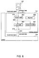
- Fig. 8 is a block diagram showing a typical functional configuration of the interface device according to this third embodiment and its relationship with the printer. Like the first and second embodiments, this interface device 101' is inserted into an expansion slot of printer 104 for connection with the printer.
- the interface device 101' comprises a RAM as temporary storage with a receive buffer 803, a send buffer 804, and a flag area 805 being reserved in the RAM.
- the flag area 805 is set, that is, stores a non-zero value, the last command data received was a real-time command.
- a temporary buffer 831 is also reserved in the RAM for temporarily storing the command data stream as it is being received if it is not known whether the command data stream being received is a real-time command.
- command data When command data is sent (811) from the host computer 102, the command data is stored in receive buffer 803. The value of the flag area 805 is set or cleared accordingly depending on whether or not the command data represents a real-time command.
- the command data stored in receive buffer 803 is appropriately copied (821) to send buffer 804 or temporary buffer 831, and is sent (813) to the printer 104.
- a busy/ready signal is sent (813) from the printer 104 to interface device 101', and the interface device 101' monitors the received signal to execute the appropriate process.
- the interface device 101' also sends (812) the busy/ready signal to the host computer 102.
- Fig. 9 is a flow chart of a 1-byte receive process activated by a receive interrupt that occurs when command data from the host computer 102 arrives (811) at the interface device 101'.
- the interface device 101' reads one byte of command data from the host interface (not shown in Fig. 9 but corresponding to 103 in Fig. 1) (step S901).
- the read command data is stored in the receive buffer (step S902).
- Storing in the receive buffer is accomplished by adding data in a FIFO (first in, first out) method.
- the receive buffer 803 can thus be achieved as a queue of a fixed maximum length (buffer length) using, for example, a ring buffer.
- the interface device 101' detects whether the receive buffer 803 is full (step S903). If the receive buffer 803 is full (step S903 returns Yes ), the interface device 101' outputs a busy signal to the host computer 102 (step S904), and this process ends. If the receive buffer 803 is not full (step S903 returns No), this process ends immediately. In this case, the busy/ready signal state (812) is held as before.
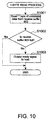
- Fig. 10 is a flow chart of a 1-byte read process activated when command data is copied (821) from the receive buffer 803 to the send buffer 804.
- Fig. 11 is a flow chart of a data copy process whereby command data is copied, for example, using the above-noted 1-byte read process. It should be noted that in this exemplary embodiment of the invention the 1-byte read process of Fig. 10 is called by the data process of Fig. 11.
- the interface device 101' when the 1-byte read process is activated, the interface device 101' reads one byte from the head of the receive buffer 803, and stores the read byte in a register, for example, in the CPU (not shown in the figure) of the interface device 101' (step S1001).
- the receive buffer 803 is a FIFO queue, and the first byte (the head of the buffer) is, therefore, the oldest one of the bytes stored in the receive buffer 803.
- step S1002 After reading one byte in step S1001, the interface device 101' detects whether the receive buffer 803 is full (step S1002). If the receive buffer 803 is not full (step S1002 returns No ), the interface device 101' sends a ready signal to the host computer 102 (step S1003), and this process ends. If the receive buffer 803 is full (step S1002 returns Yes ), this process terminates immediately. In this case, the busy/ready signal state (812) is held as before.
- this data copy process is activated when data is stored in the receive buffer 803.
- the timing at which this data copy process is executed can be appropriately selected according to the objective and application.
- the data copy process can be activated by a timer interrupt occurring at a specific time interval, when there is not other process to be performed, when the receive buffer 803 becomes full, or using a combination of these criteria.
- step S1101 the above-described 1-byte read process is executed (step S1101).
- the interface device 101' checks whether the command data read into a register, for example, by the 1-byte read process (step S1001 in Fig. 10), is the first byte of a real-time command (step S1102).
- the first byte of a real-time command is 0x10 , but the invention is not limited to this and other real-time command formats can be alternatively used. If 0x10 is not used to identify the first byte of a real-time command, it is also possible to sent 0x10 as part of a normal command.
- step S1102 If the read byte is not the first byte of a real-time command (step S1102 returns No ), the byte is written into the send buffer 804 (step S1103), and this process ends. It should be noted that the send buffer 804 is, like the receive buffer 803, a FIFO type queue. If the read byte is the first byte of a real-time command (step S1102 returns Yes ), the byte is written into the temporary buffer 831 (step S1104). The 1-byte read process is then performed again (step S1105), and the interface device 101' checks whether that read command data byte is the last byte in the command (step S1106). If not (step S1106 returns No ), the procedure loops back to step S1104.
- step S1106 If the read command data byte is the last byte in the command (step S1106 returns Yes ), interface device 101' checks whether the command data sequence that has been stored in the temporary buffer 831 and the command data byte just read in step S 1104 combine to a real-time command (step S1107). If not (step S1107 returns No ), the command data (sequence) stored in temporary buffer 831 and the last read command data byte are copied sequentially to the send buffer 804 (step S1108), the temporary buffer 831 is cleared (step S1109), and this process ends. If a real-time command is farmed (step S1107 returns Yes ), the read byte is added to those already in the temporary buffer 831 (step S1110), the flag area 805 is set (step S1111), and this process ends.
- Fig. 12 is a flow chart of a send process whereby the interface device 101' sends (812) command data stored in the send buffer 804 to the printer 104. It should be noted that this send process is started when data is stored in the send buffer 804 or temporary buffer 831. The timing at which this process is executed can be appropriately selected according to the objective and application. For example, the process can be activated by a timer interrupt occurring at a specific time interval, when there is no other process to be performed, when the send buffer 804 becomes full, when the flag area 805 is set, or using a combination of these criteria.
- step S1201 when the send process starts, the interface device 101' checks whether the flag area 805 is set (step S1201). If it is (step S1201 returns Yes ), the command data sequence for the real-time command stored in temporary buffer 831 is sent to the printer 104 (step S1202), the flag area 805 and temporary buffer 831 are cleared (step S1203), and this process ends. It should be noted that the busy/ready signal state of the printer 104 is not checked when a real-time command is to be sent to the printer 104. This is because a real-time command is sent to the printer 104 even when the printer 104 is busy or not in the RRD state.
- step S1201 If the flag area 805 is not set (step S1201 returns No ), one byte is read from the send buffer 804 (step S1204), and the interface device 101' checks whether the read byte is the first byte of a normal command comprising multiple bytes (a multiple-byte command) (step S1205). If this byte is not the first byte or if the normal command is only one byte long (step S1205 returns No ), the read byte is sent (step S1206) and this process ends.
- step S1205 If the read byte is the first byte of a normal multiple-byte command (step S1205 returns Yes ), the byte is written into the temporary buffer 831 (step S1207), another byte is read from the send buffer 804 (step S1208) and is written into the temporary buffer 831 (step S1209). Step S1210 then checks whether this other byte completes the command. If not (step S1210 returns No ), the procedure loops back to step S1208. If the byte completes the command (step S1210 returns Yes ), the command data sequence of the normal command now stored in temporary buffer 831 is sent to the printer 104 (step S1211), the temporary buffer 831 is cleared (step S1212), and this process ends.
- step S1206 and step S1211 first checks whether the printer is in the RRD state, and, if not, waits for the printer 104 to enter the RRD state before transmission begins.
- the interface device 101' received command data is first checked as to whether it represents a real-time command and, if so, the flag area 805 is set.
- a real-time command is sent with priority over other command data already stored in the send buffer 804, and real-time commands do not interfere with other commands in the sense such interference has been defined in the second embodiment.
- An interface device for a printer and a control method for the interface device can be provided such that the interface device is installed to an expansion slot of the printer and connected to a host computer to receive data sent by the host computer while monitoring the data buffering status of the printer so that data from the host computer can be appropriately buffered and sent to the printer by the interface device.
- the interface device control method of the invention can also be provided in the form of a software program recorded to a data storage medium, which can then be easily distributed and sold independently of the interface device.
- An interface device and interface device control method according to the present invention can also be achieved as a result of an interface device executing this program of the present invention recorded to a data storage medium
Landscapes
- Engineering & Computer Science (AREA)
- Theoretical Computer Science (AREA)
- General Engineering & Computer Science (AREA)
- Physics & Mathematics (AREA)
- General Physics & Mathematics (AREA)
- Human Computer Interaction (AREA)
- Power Engineering (AREA)
- Mechanical Engineering (AREA)
- Accessory Devices And Overall Control Thereof (AREA)
- Record Information Processing For Printing (AREA)
Applications Claiming Priority (4)
| Application Number | Priority Date | Filing Date | Title |
|---|---|---|---|
| JP03003599A JP3846089B2 (ja) | 1999-02-08 | 1999-02-08 | インターフェース装置、その制御方法および情報記録媒体 |
| JP3003599 | 1999-02-08 | ||
| JP2000009345A JP4441967B2 (ja) | 2000-01-18 | 2000-01-18 | インターフェース装置およびその制御方法 |
| JP2000009345 | 2000-01-18 |
Publications (3)
| Publication Number | Publication Date |
|---|---|
| EP1026599A2 true EP1026599A2 (de) | 2000-08-09 |
| EP1026599A3 EP1026599A3 (de) | 2001-06-20 |
| EP1026599B1 EP1026599B1 (de) | 2011-09-28 |
Family
ID=26368298
Family Applications (1)
| Application Number | Title | Priority Date | Filing Date |
|---|---|---|---|
| EP00102166A Expired - Lifetime EP1026599B1 (de) | 1999-02-08 | 2000-02-08 | Druckerschnittstellengerät, Steuerverfahren dafür und Datenspeichermedium |
Country Status (5)
| Country | Link |
|---|---|
| US (1) | US6768557B1 (de) |
| EP (1) | EP1026599B1 (de) |
| KR (1) | KR100549978B1 (de) |
| CN (1) | CN1134729C (de) |
| CA (1) | CA2298192C (de) |
Cited By (3)
| Publication number | Priority date | Publication date | Assignee | Title |
|---|---|---|---|---|
| WO2005066728A1 (de) * | 2004-01-09 | 2005-07-21 | Beckhoff Automation Gmbh | Verfahren, schnittstelle und netzwerk zum zyklischen versenden von ethernet-telegrammen |
| EP1717691A3 (de) * | 2005-04-18 | 2010-01-20 | Bixolon Co., Ltd. | Druckvorrichtung, Steuerverfahren dafür sowie Datenverarbeitungsvorrichtung die diese Druckvorrichtung verwendet |
| US8279475B2 (en) | 2008-05-27 | 2012-10-02 | Bixolon Co., Ltd. | Printing apparatus and method for processing real-time command using the printing apparatus |
Families Citing this family (10)
| Publication number | Priority date | Publication date | Assignee | Title |
|---|---|---|---|---|
| JP4560917B2 (ja) * | 1999-10-15 | 2010-10-13 | セイコーエプソン株式会社 | プリンタ及びその制御方法 |
| US7088466B1 (en) * | 1999-11-15 | 2006-08-08 | Canon Kabushiki Kaisha | Print system and data transfer apparatus and method |
| US7202981B2 (en) * | 2001-11-01 | 2007-04-10 | Kuo-Jeng Wang | Method and system for increasing scanning speed |
| US7420715B2 (en) * | 2001-12-11 | 2008-09-02 | Transpacific Ip, Ltd. | Method and system for promoting scanning speed |
| US7460257B2 (en) * | 2002-11-04 | 2008-12-02 | Chen-Ho Lee | Technique for transferring image information from a scanning apparatus |
| KR101054307B1 (ko) * | 2008-05-27 | 2011-08-08 | 주식회사 빅솔론 | 프린트 장치 및 프린트 장치의 실시간 명령 처리 방법 |
| US8170062B2 (en) * | 2009-04-29 | 2012-05-01 | Intel Corporation | Packetized interface for coupling agents |
| EP2282268B1 (de) * | 2009-07-23 | 2012-11-21 | STMicroelectronics Srl | Schnittstellenvorrichtung und -verfahren, beispielsweise für System-on-Chip |
| CN102149085B (zh) * | 2011-04-21 | 2014-01-15 | 惠州Tcl移动通信有限公司 | 移动终端及其多接入点管理方法 |
| US20170293490A1 (en) * | 2016-04-11 | 2017-10-12 | Aqua Products, Inc. | Method for modifying an onboard control system of a pool cleaner, and power source for a pool cleaner |
Citations (2)
| Publication number | Priority date | Publication date | Assignee | Title |
|---|---|---|---|---|
| EP0654757A2 (de) | 1993-11-16 | 1995-05-24 | Seiko Epson Corporation | Druckvorrichtung und Steuerungsverfahren dafür |
| EP0769737A2 (de) | 1995-10-13 | 1997-04-23 | Seiko Epson Corporation | Drucker und Verfahren mit Kassenschubladen-Steuerfunktion |
Family Cites Families (13)
| Publication number | Priority date | Publication date | Assignee | Title |
|---|---|---|---|---|
| US4071909A (en) * | 1976-09-30 | 1978-01-31 | Xerox Corporation | Digital interface system for a printer |
| JPS5957337A (ja) | 1982-06-04 | 1984-04-02 | コンピユ−タ−ズ・インタ−ナシヨナル・インコ−ポレ−テツド | ユニバ−サルコンピユ−タ−プリンタインタ−フエイス |
| US5485590A (en) | 1990-01-08 | 1996-01-16 | Allen-Bradley Company, Inc. | Programmable controller communication interface module which is configurable by a removable memory cartridge |
| JP3334211B2 (ja) * | 1993-02-10 | 2002-10-15 | 株式会社日立製作所 | ディスプレイ |
| JPH0728612A (ja) * | 1993-07-12 | 1995-01-31 | Brother Ind Ltd | プリンタ |
| JPH0784735A (ja) * | 1993-09-09 | 1995-03-31 | Casio Electron Mfg Co Ltd | プリンタの入力制御装置 |
| SG66232A1 (en) | 1993-11-08 | 1999-07-20 | Seiko Epson Corp | Printing apparatus control method therefor and data processing apparatus using the printing apparatus |
| JPH08147116A (ja) * | 1994-11-22 | 1996-06-07 | Hitachi Ltd | バッファ装置 |
| JP3658044B2 (ja) * | 1995-06-22 | 2005-06-08 | キヤノン株式会社 | プリンタ制御装置及び方法 |
| US6055361A (en) | 1995-06-22 | 2000-04-25 | Canon Kabushiki Kaisha | Printer control with monitor function |
| JP2000501184A (ja) * | 1995-11-30 | 2000-02-02 | クロマビジョン メディカル システムズ,インコーポレイテッド | 生体標本の自動画像分析の方法および装置 |
| JPH09323463A (ja) * | 1996-06-05 | 1997-12-16 | Seiko Epson Corp | 通信端末およびその制御方法 |
| JPH10333856A (ja) | 1997-06-04 | 1998-12-18 | Seiko Epson Corp | 通信端末およびその制御方法、並びに当該制御プログラムが記録されたコンピュータ読み取り可能な記録媒体 |
-
2000
- 2000-02-07 KR KR1020000005590A patent/KR100549978B1/ko not_active Expired - Fee Related
- 2000-02-07 CA CA002298192A patent/CA2298192C/en not_active Expired - Fee Related
- 2000-02-08 US US09/500,133 patent/US6768557B1/en not_active Expired - Lifetime
- 2000-02-08 EP EP00102166A patent/EP1026599B1/de not_active Expired - Lifetime
- 2000-02-12 CN CNB001023241A patent/CN1134729C/zh not_active Expired - Fee Related
Patent Citations (2)
| Publication number | Priority date | Publication date | Assignee | Title |
|---|---|---|---|---|
| EP0654757A2 (de) | 1993-11-16 | 1995-05-24 | Seiko Epson Corporation | Druckvorrichtung und Steuerungsverfahren dafür |
| EP0769737A2 (de) | 1995-10-13 | 1997-04-23 | Seiko Epson Corporation | Drucker und Verfahren mit Kassenschubladen-Steuerfunktion |
Cited By (6)
| Publication number | Priority date | Publication date | Assignee | Title |
|---|---|---|---|---|
| WO2005066728A1 (de) * | 2004-01-09 | 2005-07-21 | Beckhoff Automation Gmbh | Verfahren, schnittstelle und netzwerk zum zyklischen versenden von ethernet-telegrammen |
| US7853706B2 (en) | 2004-01-09 | 2010-12-14 | Beckhoff Automation Gmbh | Method, interface and network for cyclical sending of Ethernet telegrams |
| EP1717691A3 (de) * | 2005-04-18 | 2010-01-20 | Bixolon Co., Ltd. | Druckvorrichtung, Steuerverfahren dafür sowie Datenverarbeitungsvorrichtung die diese Druckvorrichtung verwendet |
| US8130393B2 (en) | 2005-04-18 | 2012-03-06 | Bixolon Co. Ltd. | Printing apparatus, control method therefor, and data processing apparatus using the printing apparatus |
| US8279475B2 (en) | 2008-05-27 | 2012-10-02 | Bixolon Co., Ltd. | Printing apparatus and method for processing real-time command using the printing apparatus |
| EP2128799A3 (de) * | 2008-05-27 | 2014-10-29 | Bixolon Co., Ltd. | Druckvorrichtung und Verfahren zur Verarbeitung eines Echtzeitbefehls unter Verwendung der Druckvorrichtung |
Also Published As
| Publication number | Publication date |
|---|---|
| CN1134729C (zh) | 2004-01-14 |
| CA2298192C (en) | 2005-09-13 |
| EP1026599B1 (de) | 2011-09-28 |
| CN1263294A (zh) | 2000-08-16 |
| KR100549978B1 (ko) | 2006-02-08 |
| CA2298192A1 (en) | 2000-08-08 |
| EP1026599A3 (de) | 2001-06-20 |
| KR20000076610A (ko) | 2000-12-26 |
| HK1030070A1 (en) | 2001-04-20 |
| US6768557B1 (en) | 2004-07-27 |
Similar Documents
| Publication | Publication Date | Title |
|---|---|---|
| CA2197383C (en) | Method and apparatus for providing print job buffering for a printer on a fast data path | |
| EP0989483B1 (de) | Seitendrucker und Seitendrucksystem | |
| EP1026599B1 (de) | Druckerschnittstellengerät, Steuerverfahren dafür und Datenspeichermedium | |
| US6321266B1 (en) | Input/output apparatus connected to a plurality of host computers via a network | |
| EP0477947A2 (de) | Schalter zur gemeinsamen Benutzung eines Peripheriegeräts | |
| EP0477945A2 (de) | System zu gemeinsamer Benutzung von Geräten, die PCL Makros gebrauchen | |
| US5175762A (en) | Remote printing using FAX | |
| US7961340B2 (en) | Printer, printing system and printing method for preventing abnormal printing | |
| US6741606B1 (en) | Interface control apparatus | |
| EP1391827B1 (de) | Übertragungsvorrichtung und übertragungsverfahren | |
| US5926650A (en) | Method and system utilizing a negotiation phase to transfer commands and data in separate modes over a host/peripheral interface | |
| US20010043361A1 (en) | Printer detecting data precisely in response to change in data transmission speed | |
| US7212303B2 (en) | Print control method for a multifunctional printer including a facsimile feature | |
| EP0685784B1 (de) | Datenempfangssystem | |
| JP4441967B2 (ja) | インターフェース装置およびその制御方法 | |
| JP3189269B2 (ja) | ネットワークプリンタ | |
| JP3846089B2 (ja) | インターフェース装置、その制御方法および情報記録媒体 | |
| US6154287A (en) | Printing device | |
| JP2005349768A (ja) | 印刷装置及び印刷方法 | |
| JP2003248558A (ja) | データ転送方法、および、その装置 | |
| JPH0774911A (ja) | ファクシミリとコンピューターシステム間の画像情報伝送時プロトコル制御のための制御情報のフォーマット構造 | |
| EP0484145B1 (de) | Ferndrucker mit Fax | |
| JPH10309835A (ja) | ページプリンタ | |
| EP0855641B1 (de) | Drucker, der Daten genau in Entsprechung zur Änderung in der Datenübertragungsgeschwindigkeit erkennt | |
| JP2658931B2 (ja) | プリンタコントローラ |
Legal Events
| Date | Code | Title | Description |
|---|---|---|---|
| PUAI | Public reference made under article 153(3) epc to a published international application that has entered the european phase |
Free format text: ORIGINAL CODE: 0009012 |
|
| AK | Designated contracting states |
Kind code of ref document: A2 Designated state(s): DE FR GB IT NL |
|
| AX | Request for extension of the european patent |
Free format text: AL;LT;LV;MK;RO;SI |
|
| PUAL | Search report despatched |
Free format text: ORIGINAL CODE: 0009013 |
|
| AK | Designated contracting states |
Kind code of ref document: A3 Designated state(s): AT BE CH CY DE DK ES FI FR GB GR IE IT LI LU MC NL PT SE |
|
| AX | Request for extension of the european patent |
Free format text: AL;LT;LV;MK;RO;SI |
|
| RIC1 | Information provided on ipc code assigned before grant |
Free format text: 7G 06F 3/12 A, 7G 06F 13/38 B, 7G 06F 13/12 B |
|
| 17P | Request for examination filed |
Effective date: 20011130 |
|
| AKX | Designation fees paid |
Free format text: DE FR GB IT NL |
|
| 17Q | First examination report despatched |
Effective date: 20080826 |
|
| R17C | First examination report despatched (corrected) |
Effective date: 20080909 |
|
| GRAP | Despatch of communication of intention to grant a patent |
Free format text: ORIGINAL CODE: EPIDOSNIGR1 |
|
| GRAS | Grant fee paid |
Free format text: ORIGINAL CODE: EPIDOSNIGR3 |
|
| GRAA | (expected) grant |
Free format text: ORIGINAL CODE: 0009210 |
|
| AK | Designated contracting states |
Kind code of ref document: B1 Designated state(s): DE FR GB IT NL |
|
| REG | Reference to a national code |
Ref country code: GB Ref legal event code: FG4D |
|
| REG | Reference to a national code |
Ref country code: NL Ref legal event code: T3 |
|
| REG | Reference to a national code |
Ref country code: DE Ref legal event code: R096 Ref document number: 60046471 Country of ref document: DE Effective date: 20111208 |
|
| PLBE | No opposition filed within time limit |
Free format text: ORIGINAL CODE: 0009261 |
|
| STAA | Information on the status of an ep patent application or granted ep patent |
Free format text: STATUS: NO OPPOSITION FILED WITHIN TIME LIMIT |
|
| 26N | No opposition filed |
Effective date: 20120629 |
|
| REG | Reference to a national code |
Ref country code: DE Ref legal event code: R097 Ref document number: 60046471 Country of ref document: DE Effective date: 20120629 |
|
| REG | Reference to a national code |
Ref country code: FR Ref legal event code: PLFP Year of fee payment: 17 |
|
| REG | Reference to a national code |
Ref country code: FR Ref legal event code: PLFP Year of fee payment: 18 |
|
| PGFP | Annual fee paid to national office [announced via postgrant information from national office to epo] |
Ref country code: NL Payment date: 20170110 Year of fee payment: 18 |
|
| PGFP | Annual fee paid to national office [announced via postgrant information from national office to epo] |
Ref country code: FR Payment date: 20170112 Year of fee payment: 18 Ref country code: DE Payment date: 20170131 Year of fee payment: 18 |
|
| PGFP | Annual fee paid to national office [announced via postgrant information from national office to epo] |
Ref country code: GB Payment date: 20170208 Year of fee payment: 18 |
|
| PGFP | Annual fee paid to national office [announced via postgrant information from national office to epo] |
Ref country code: IT Payment date: 20170221 Year of fee payment: 18 |
|
| REG | Reference to a national code |
Ref country code: DE Ref legal event code: R119 Ref document number: 60046471 Country of ref document: DE |
|
| REG | Reference to a national code |
Ref country code: NL Ref legal event code: MM Effective date: 20180301 |
|
| GBPC | Gb: european patent ceased through non-payment of renewal fee |
Effective date: 20180208 |
|
| REG | Reference to a national code |
Ref country code: FR Ref legal event code: ST Effective date: 20181031 |
|
| PG25 | Lapsed in a contracting state [announced via postgrant information from national office to epo] |
Ref country code: NL Free format text: LAPSE BECAUSE OF NON-PAYMENT OF DUE FEES Effective date: 20180301 |
|
| PG25 | Lapsed in a contracting state [announced via postgrant information from national office to epo] |
Ref country code: DE Free format text: LAPSE BECAUSE OF NON-PAYMENT OF DUE FEES Effective date: 20180901 |
|
| PG25 | Lapsed in a contracting state [announced via postgrant information from national office to epo] |
Ref country code: GB Free format text: LAPSE BECAUSE OF NON-PAYMENT OF DUE FEES Effective date: 20180208 Ref country code: FR Free format text: LAPSE BECAUSE OF NON-PAYMENT OF DUE FEES Effective date: 20180228 Ref country code: IT Free format text: LAPSE BECAUSE OF NON-PAYMENT OF DUE FEES Effective date: 20180208 |