EP1026487A2 - Etalon Spektrometer mit doppeltem Strahldurchgang - Google Patents
Etalon Spektrometer mit doppeltem Strahldurchgang Download PDFInfo
- Publication number
- EP1026487A2 EP1026487A2 EP00101694A EP00101694A EP1026487A2 EP 1026487 A2 EP1026487 A2 EP 1026487A2 EP 00101694 A EP00101694 A EP 00101694A EP 00101694 A EP00101694 A EP 00101694A EP 1026487 A2 EP1026487 A2 EP 1026487A2
- Authority
- EP
- European Patent Office
- Prior art keywords
- spectrometer
- etalon
- light
- diffuse
- optic
- Prior art date
- Legal status (The legal status is an assumption and is not a legal conclusion. Google has not performed a legal analysis and makes no representation as to the accuracy of the status listed.)
- Granted
Links
Images



Classifications
-
- G—PHYSICS
- G01—MEASURING; TESTING
- G01J—MEASUREMENT OF INTENSITY, VELOCITY, SPECTRAL CONTENT, POLARISATION, PHASE OR PULSE CHARACTERISTICS OF INFRARED, VISIBLE OR ULTRAVIOLET LIGHT; COLORIMETRY; RADIATION PYROMETRY
- G01J3/00—Spectrometry; Spectrophotometry; Monochromators; Measuring colours
- G01J3/12—Generating the spectrum; Monochromators
- G01J3/26—Generating the spectrum; Monochromators using multiple reflection, e.g. Fabry-Perot interferometer, variable interference filters
-
- G—PHYSICS
- G01—MEASURING; TESTING
- G01J—MEASUREMENT OF INTENSITY, VELOCITY, SPECTRAL CONTENT, POLARISATION, PHASE OR PULSE CHARACTERISTICS OF INFRARED, VISIBLE OR ULTRAVIOLET LIGHT; COLORIMETRY; RADIATION PYROMETRY
- G01J3/00—Spectrometry; Spectrophotometry; Monochromators; Measuring colours
- G01J3/28—Investigating the spectrum
-
- G—PHYSICS
- G01—MEASURING; TESTING
- G01J—MEASUREMENT OF INTENSITY, VELOCITY, SPECTRAL CONTENT, POLARISATION, PHASE OR PULSE CHARACTERISTICS OF INFRARED, VISIBLE OR ULTRAVIOLET LIGHT; COLORIMETRY; RADIATION PYROMETRY
- G01J3/00—Spectrometry; Spectrophotometry; Monochromators; Measuring colours
- G01J3/02—Details
-
- G—PHYSICS
- G01—MEASURING; TESTING
- G01J—MEASUREMENT OF INTENSITY, VELOCITY, SPECTRAL CONTENT, POLARISATION, PHASE OR PULSE CHARACTERISTICS OF INFRARED, VISIBLE OR ULTRAVIOLET LIGHT; COLORIMETRY; RADIATION PYROMETRY
- G01J3/00—Spectrometry; Spectrophotometry; Monochromators; Measuring colours
- G01J3/02—Details
- G01J3/0205—Optical elements not provided otherwise, e.g. optical manifolds, diffusers, windows
-
- G—PHYSICS
- G01—MEASURING; TESTING
- G01J—MEASUREMENT OF INTENSITY, VELOCITY, SPECTRAL CONTENT, POLARISATION, PHASE OR PULSE CHARACTERISTICS OF INFRARED, VISIBLE OR ULTRAVIOLET LIGHT; COLORIMETRY; RADIATION PYROMETRY
- G01J3/00—Spectrometry; Spectrophotometry; Monochromators; Measuring colours
- G01J3/02—Details
- G01J3/0205—Optical elements not provided otherwise, e.g. optical manifolds, diffusers, windows
- G01J3/021—Optical elements not provided otherwise, e.g. optical manifolds, diffusers, windows using plane or convex mirrors, parallel phase plates, or particular reflectors
-
- G—PHYSICS
- G01—MEASURING; TESTING
- G01J—MEASUREMENT OF INTENSITY, VELOCITY, SPECTRAL CONTENT, POLARISATION, PHASE OR PULSE CHARACTERISTICS OF INFRARED, VISIBLE OR ULTRAVIOLET LIGHT; COLORIMETRY; RADIATION PYROMETRY
- G01J3/00—Spectrometry; Spectrophotometry; Monochromators; Measuring colours
- G01J3/02—Details
- G01J3/0205—Optical elements not provided otherwise, e.g. optical manifolds, diffusers, windows
- G01J3/0224—Optical elements not provided otherwise, e.g. optical manifolds, diffusers, windows using polarising or depolarising elements
-
- G—PHYSICS
- G01—MEASURING; TESTING
- G01J—MEASUREMENT OF INTENSITY, VELOCITY, SPECTRAL CONTENT, POLARISATION, PHASE OR PULSE CHARACTERISTICS OF INFRARED, VISIBLE OR ULTRAVIOLET LIGHT; COLORIMETRY; RADIATION PYROMETRY
- G01J3/00—Spectrometry; Spectrophotometry; Monochromators; Measuring colours
- G01J3/02—Details
- G01J3/0205—Optical elements not provided otherwise, e.g. optical manifolds, diffusers, windows
- G01J3/0229—Optical elements not provided otherwise, e.g. optical manifolds, diffusers, windows using masks, aperture plates, spatial light modulators or spatial filters, e.g. reflective filters
-
- G—PHYSICS
- G01—MEASURING; TESTING
- G01J—MEASUREMENT OF INTENSITY, VELOCITY, SPECTRAL CONTENT, POLARISATION, PHASE OR PULSE CHARACTERISTICS OF INFRARED, VISIBLE OR ULTRAVIOLET LIGHT; COLORIMETRY; RADIATION PYROMETRY
- G01J3/00—Spectrometry; Spectrophotometry; Monochromators; Measuring colours
- G01J3/02—Details
- G01J3/027—Control of working procedures of a spectrometer; Failure detection; Bandwidth calculation
Definitions
- This invention relates to spectrometers and especially to etalon based spectrometers.
- Etalon based spectrometers are well known devices for measuring the intensity of light in a beam as a function of wavelength.
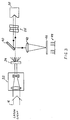
- FIG. 1 shows the features of a prior art etalon spectrometer used for measurement of wavelength and bandwidth of a laser beam 16. The beam is diffused by diffuser 2 so that rays propogating in a very large number of angles illuminate etalon 4.
- FIG. 1 shows a single ray 20 being reflected many times within the etalon gap between surfaces 8A and 8B which are coated to reflect about 90%.
- Spectral components which are transmitted through the etalon are focused by lens 14 onto photo diode array 12.
- Photo diode array 12 registers a fringe pattern 15 which can be read using electronic data acquisition boards (not shown).
- the transmission or reflection of light incident on an etalon such as that depicted is well understood and depends on the design of the etalon, particularly the reflectance of the two reflecting surfaces.
- Etalon spectrometers are widely used to measure the spectrum of lasers.
- a particularly important use of etalon spectrometers is to measure the bandwidth of line narrowed excimer lasers such as the line narrowed KrF excimer laser.
- line narrowed excimer lasers such as the line narrowed KrF excimer laser.
- These lasers are used, for example, as light sources for deep-UV microlithography.
- the prior art etalon spectrometer is capable of accurately measuring ⁇ FWHM values, and is currently used for this purpose in production microlithography lasers, such as manufactured by CYMER, Inc. (San Diego, CA).
- prior art etalon spectrometers are not very suitable for accurately measuring ⁇ 95% values.
- Typical production quality KrF excimer lasers should have a ⁇ FWHM of about 0.6 pm and ⁇ 95% of about 2 pm, if operating properly.
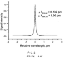
- FIG. 2 shows the calculated slit function spectrum of a typical prior art etalon having a free spectral range (FSR) of 5 pm and a coefficient of finesse (finesse) of 38.
- FSR and finesse are defined and explained in a variety of optic texts such as OPTICS by Eugene Hecht/Alfred Zajae published by Addison-Wesley, Reading, Massachusetts.
- the slit function spectrum of FIG. 2 can be derived from one of the peaks of fringe pattern 15.
- the calculation graphed in FIG. 2 assumes that the light illuminating the etalon is monochomatic (i.e., an infinitely narrow bandwidth).
- the slit function bandwidth of the etalon is a source of error and contributes to uncertainty or error in the measurement.
- the calculated FWHM bandwidth for this prior art etalon is 0.13 pm and the 95% integral bandwidth for the etalon is about 1.5 pm.
- the slit function bandwidth of the etalon itself should be substantially smaller than the laser bandwidth. While this condition is satisfied for ⁇ FWHM measurements, where etalon slit function FWHM of 0.13 pm is substantially smaller than typical laser ⁇ FWHM of about 0.6 pm, the same is not true for ⁇ 95% measurements, where etalon slit function bandwidth of about 1.5 pm is a substantial fraction of the expected laser bandwidth of about 2 pm.
- Another way of accurately measuring laser spectrum is to use a high resolution grating spectrometers. These instruments can provide accurate spectral measurement including accurate ⁇ 95% measurements, but are very bulky and expensive. These instruments are successfully used in the laboratory but are not well suited for production line microlithography use.
- the present invention provides a double pass etalon based spectrometer. Spectral components of a diffused beam are angularly separated as they are transmitted through an etalon. A retroreflector reflects the transmitted components back through the etalon. Twice transmitted spectral components are focused onto a light detector which in a preferred embodiment is a photo diode array.
- the spectrometer is very compact producing precise fringe data permitting bandwidth measurements with precision needed for microlithography for both ⁇ FWHM and ⁇ 95% .
- FIG. 3 shows a preferred embodiment of the present invention.
- a laser beam 16, whose size is reduced three times using telescope 32 illuminates diffuser 34.
- Light scattered from diffuser 34 illuminates etalon 25.
- Hollow retro-reflector 38 is used to return the beam back to the etalon for the second pass.
- Each component of the beam is reflected at exactly or almost exactly 180-degrees for a second pass through etalon 25 but there are small displacements of the reflected components. These small displacement permit the use of a 45-degree mirror 40 which reflects beam components after double-passes through the etalon, but allows passage of a sufficient portion of the incoming beam.
- the reflected beam components are focused by lens 42 with a 1 meter focal length onto linear photo diode array (PDA) 44, where a fringe pattern 49 is detected.
- PDA linear photo diode array
- the preferred PDA is a 2048 element, 14 ⁇ x 14 ⁇ array available from supplier such as EG&G, Inc., Sunnyvale, CA.
- the fringe pattern 49 consists of multiple peaks located in the same position as the peaks 15 of prior art etalon of FIG. 15. The difference though is that the peaks of the etalon of the present invention more closely match the actual laser spectrum because of improved resolution of etalon spectrometer in this double pass configuration.
- FIG. 4 shows a spectrum (recorded with PDA 44) of the beam from a frequency doubled Ar-ion cw laser which emits light at 248.25 with an extremely narrow spectral bandwidth of only about 0.003 (FWHM).
- FWHM spectral bandwidth
- the light spectrum from this laser is narrow enough to be considered monochomatic for purposes of testing etalons with bandwidths in the ranges greater than 0.1 pm.
- the FWHM bandwidth recorded by PDA 44 (as shown in FIG. 3) was about 0.12 pm with a 95 percent integral value of 0.33 pm.
- the theoretical values for two perfect etalons in series under the above conditions would be 0.09 pm (FWHM) and 0.25 (95% integral).
- Applicant has compared a typical spectrum of a microlithography KrF laser measured with a high resolution grating spectrometer and a compact spectrometer of the present invention.
- the grating spectrometer had a slit function of about 0.12 pm at FWHM level and was manufactured by CYMER, Inc. with offices in San Diego, California for the purpose of testing KrF excimer lasers. Very good agreement between the results obtained with etalon spectrometer and grating spectrometer were obtained.
- the FWHM value of the laser bandwidth was 0.65 pm and 0.62 pm as measured by double pass etalon of the present invention and grating spectrometers respectively, while 95% integrated value of the bandwidth is 1.67 pm and 1.70 pm as measured by double pass etalon spectrometer of the present invention and high resolution grating spectrometer, respectively.
- the double pass etalon spectrometer of the present invention creates a fringe pattern similar to conventional etalon spectrometer the differences being that the fringes correspond to actual spectrum more closely and are less convolved by etalon resolution. Therefore, any of the well known techniques can be used to analyze the fringe pattern.
- This etalon spectrometer can also be used in combination with a relatively low resolution grating spectrometer to render accurate center wavelength measurements. Such applications are described, for example, in U.S. Patents 5,025,445 and 5,450,207.
- the etalon spectrometer alone cannot do the absolute wavelength measurements; therefore, a method to calibrate the etalon data is needed.
- a plurality of center wavelengths can be obtained from the etalon separated exactly by the free spectral range (FSR) of the etalon.
- FSR free spectral range
- the FSR is about 5 pm.
- a low resolution grating spectrometer may be used as explained in U.S. Patent 5,025,445.
- the resolution of that grating spectrometer can be about half of the FSR, therefore, a unique center wavelength value can be chosen.
- a preferred calibration technique is described in U.S. Patent 5,450,207.
- FIG. 5 A second preferred embodiment of the present invention is shown in FIG. 5.
- a laser beam 16 illuminates diffuser 34 after being reduced in size by telescope 32 in a way similar to the first embodiment.
- a spatial filter 52 is used to select a portion of diffused light.
- the spatial filter 52 consists of two lenses 54 and 58 with a focal length of 10 cm each, separated by a distance, twice the focal length, or about 20 cm.
- An aluminum aperture 56 with a diameter of about 0.1 cm is placed at the focus of lens 54.
- the purpose of spatial filter 52 is to select a fan of rays coming from a diffuser within an angle (spatial frequencies) of about 0.01 steradian. This filtered fan of rays is incident on beam splitter 46.
- Beam splitter 46 is a partially reflecting mirror, which transmits about 50% of the light and reflects the rest away (not shown).
- Light passing through etalon 25 is reflected by hollow retroreflector 70 which returns the beam back to the etalon for the second pass. This reflected portion of the beam is shown as 64.
- Each component of the beam is reflected at exactly or almost exactly 180-degrees for the second pass through the etalon 25.
- beam splitter 46 About 50% of the portion of the beam 64 passing through the etalon 25 is reflected by beam splitter 46. This reflected portion is focused by lens 42 having a 1 meter focal length onto linear PDA array 44, where a fringe pattern is detected.
- etalon 25 is tilted at a small angle of about 0.01 rad. relative to the axis of the incoming fan beam transmitted through spatial filter 52.
- These fringes 45A also depicted on FIG. 5 are created by a portion of original beam 62 reflected by etalon 25 on the first pass. This set of reflection fringes look different than fringe set 45B.
- Fringes 45A are dips, while fringes 45B are peaks. Because intensity of the beam after double pass through the etalon might be significantly smaller, then intensity of the beam reflected from the etalon, an optional light reducing filter 48 can be placed over the portion of the PDA, where fringe set 45A is formed. This optional filter 48 can be a neutral density filter with transmission of about 30%.
- FIG. 7 shows the relative orientation of fringes 45A and 45B on PDA 44. If there were no spatial filter 52 and etalon 25 had not have been tilted, both reflection fringes 45A and double transmission fringes 45B would have been created as concentric circles in the plane of PDA 44.
- the diameters of these circles for fringes 45A and 45B would have been exactly the same, therefore they would tend to cancel each other.
- the purpose of spatial filter 52 is to limit light available for fringes so that only a portion of circle 45 is formed.
- the purpose of tilting the etalon is to separate the portions of the circle 45 created by reflected (45A) and transmitted (45B) beams as is shown in FIG. 7. Therefore, PDA 44 detects portions of both reflected and transmitted circles but the ray detects the left side of one circle and the right side of the other circle.
- fringes 45B can be used to analyze spectrum shape, while the actual wavelength is determined by a diameter of fringe 45 (FIG. 7) together with calibration data.
- this diameter is determined as a distance between peaks 15A and 15B (FIG. 1).
- this diameter is determined as a distance between peaks 45B and corresponding dips 45A (FIG. 5). Therefore, all the prior art techniques for determining the spectral shape and center wavelength information can be used with the etalon of the present invention as well.
- FIG. 8 A third embodiment of the present invention is shown in FIG. 8.
- This embodiment is just like the second referred embodiment shown in FIG. 5 except:
- FIG. 9 shows the prism 72 as seen along direction of the beam 62 (FIG. 8).
- FIG. 9 shows the orientation of the polarization 162 of the beam 62 (shown in FIG. 8) relative to line 72C, as well as polarization 164 of the reflected light.
- This polarization 164 is rotated by 90 degrees after being reflected back by hollow prism 72. Going back to FIG. 8, this back reflected light goes through the etalon 37 for the second time just like in the second embodiment (FIG. 5). Because of its 90 degrees rotated polarization, this double pass beam 64 will now be reflected by polarizing beam splitter 47 and focused by lens 42 onto PDA array 44 to form fringe patterns 45A and 45B similar to the second embodiment (FIG. 5).
- the amplitude of the signal detected by PDA 44 is higher because of higher throughput, provided by polarizing beam splitter 47 as compared with 50% reflector 46 in the second embodiment (FIG. 5).
- the fringe pattern in this embodiment is similar to that of the second embodiment, therefore, all the same techniques for measuring spectrum shape and center wavelength can be used with this embodiment as well.
- the preferred polarizing beam splitter 47 will have about 90% transmission for one polarization and more than 97% reflection for the other.
- the gap for two passes remains the same as long as the etalon is of good quality with precisely parallel reflecting surfaces.
- the Applicant has tested first and second embodiments with great success.
- a scanning exit slit and a photometer can be used instead of photo diode array if fast response is not a requirement.
- This slit-photometer assembly can scan the area of the PDA and measure the light intensity at different wavelengths.
- the etalon of the present invention can be used in a combination with another spectrometer, such as relatively lower resolution grating spectrometer, etc. Therefore, the invention is only to be limited by the claims and their legal equivalents.
Landscapes
- Physics & Mathematics (AREA)
- Spectroscopy & Molecular Physics (AREA)
- General Physics & Mathematics (AREA)
- Spectrometry And Color Measurement (AREA)
- Analysing Materials By The Use Of Radiation (AREA)
- Investigating Or Analysing Materials By Optical Means (AREA)
Applications Claiming Priority (2)
| Application Number | Priority Date | Filing Date | Title |
|---|---|---|---|
| US09/245,134 US6243170B1 (en) | 1999-02-04 | 1999-02-04 | Double pass etalon spectrometer |
| US245134 | 1999-02-04 |
Related Child Applications (1)
| Application Number | Title | Priority Date | Filing Date |
|---|---|---|---|
| EP07021652 Division | 2007-11-07 |
Publications (3)
| Publication Number | Publication Date |
|---|---|
| EP1026487A2 true EP1026487A2 (de) | 2000-08-09 |
| EP1026487A3 EP1026487A3 (de) | 2000-12-13 |
| EP1026487B1 EP1026487B1 (de) | 2008-05-28 |
Family
ID=22925424
Family Applications (1)
| Application Number | Title | Priority Date | Filing Date |
|---|---|---|---|
| EP00101694A Expired - Lifetime EP1026487B1 (de) | 1999-02-04 | 2000-02-03 | Etalon Spektrometer mit doppeltem Strahldurchgang |
Country Status (7)
| Country | Link |
|---|---|
| US (1) | US6243170B1 (de) |
| EP (1) | EP1026487B1 (de) |
| JP (1) | JP3624783B2 (de) |
| KR (1) | KR100356108B1 (de) |
| AT (1) | ATE397201T1 (de) |
| DE (1) | DE60038994D1 (de) |
| TW (1) | TW459125B (de) |
Cited By (2)
| Publication number | Priority date | Publication date | Assignee | Title |
|---|---|---|---|---|
| DE10239509A1 (de) * | 2002-06-07 | 2004-01-08 | Delta Electronics, Inc. | Optische Fabry-Perot-Filtervorrichtung |
| JP2019510212A (ja) * | 2016-02-12 | 2019-04-11 | ザ ジェネラル ホスピタル コーポレイション | 分光法を実施するためのシステム |
Families Citing this family (28)
| Publication number | Priority date | Publication date | Assignee | Title |
|---|---|---|---|---|
| US6160832A (en) | 1998-06-01 | 2000-12-12 | Lambda Physik Gmbh | Method and apparatus for wavelength calibration |
| US7006541B2 (en) * | 1998-06-01 | 2006-02-28 | Lambda Physik Ag | Absolute wavelength calibration of lithography laser using multiple element or tandem see through hollow cathode lamp |
| US6580517B2 (en) | 2000-03-01 | 2003-06-17 | Lambda Physik Ag | Absolute wavelength calibration of lithography laser using multiple element or tandem see through hollow cathode lamp |
| US6597462B2 (en) | 2000-03-01 | 2003-07-22 | Lambda Physik Ag | Laser wavelength and bandwidth monitor |
| US6819429B2 (en) * | 2000-04-07 | 2004-11-16 | Exfo Electro-Optical Engineering Inc. | Multi-pass optical spectrum analyzer having a polarization-dependent tunable filter |
| US6807205B1 (en) | 2000-07-14 | 2004-10-19 | Lambda Physik Ag | Precise monitor etalon calibration technique |
| US6747741B1 (en) * | 2000-10-12 | 2004-06-08 | Lambda Physik Ag | Multiple-pass interferometric device |
| US20030161374A1 (en) * | 2001-11-21 | 2003-08-28 | Lambda Physik Ag | High-resolution confocal Fabry-Perot interferometer for absolute spectral parameter detection of excimer laser used in lithography applications |
| US6788726B2 (en) * | 2002-02-26 | 2004-09-07 | New Focus, Inc. | External cavity laser with high spectral purity output |
| IL159249A0 (en) * | 2002-04-23 | 2004-06-01 | Small packaged spectroscopic sensor unit | |
| US6741348B2 (en) | 2002-04-29 | 2004-05-25 | The Curators Of The University Of Missouri | Ultrasensitive spectrophotometer |
| US20040071181A1 (en) * | 2002-10-15 | 2004-04-15 | Rong Huang | Retro-reflective etalon and the devices using the same |
| US20040141182A1 (en) * | 2002-12-16 | 2004-07-22 | Thomas Schroder | Monitoring of spectral purity and advanced spectral characteristics of a narrow bandwidth excimer laser |
| US7030991B1 (en) * | 2003-08-01 | 2006-04-18 | Ball Aerospace & Technologies Corp. | Field condensing imaging system for remote sensing of atmospheric trace gases |
| US7050215B1 (en) | 2003-08-01 | 2006-05-23 | Ball Aerospace & Technologies Corp. | Method and apparatus for providing a gas correlation filter for remote sensing of atmospheric trace gases |
| US7268881B2 (en) * | 2004-02-17 | 2007-09-11 | The Curators Of The University Of Missouri | Light scattering detector |
| US7903252B2 (en) * | 2005-01-13 | 2011-03-08 | The Curators Of The University Of Missouri | Noise cancellation in fourier transform spectrophotometry |
| CN101755204A (zh) | 2006-03-09 | 2010-06-23 | 全技术联合公司 | 蒸发光散射检测器 |
| US7817274B2 (en) | 2007-10-05 | 2010-10-19 | Jingyun Zhang | Compact spectrometer |
| WO2009070459A1 (en) | 2007-11-30 | 2009-06-04 | Jingyun Zhang | Miniature spectrometers working with cellular phones and other portable electronic devices |
| WO2009152321A1 (en) * | 2008-06-11 | 2009-12-17 | The Curators Of The University Of Missouri | Liquid chromatography detector and flow controller therefor |
| DE102008050867B4 (de) * | 2008-09-30 | 2011-12-08 | Carl Zeiss Laser Optics Gmbh | Verfahren zum Messen eines Spektrums einer schmalbandigen Lichtquelle sowie Spektrometeranordnung |
| JP5502623B2 (ja) * | 2010-07-07 | 2014-05-28 | 浜松ホトニクス株式会社 | 分光装置 |
| US8599381B2 (en) | 2011-01-19 | 2013-12-03 | Massachusetts Institute Of Technology | Gas detector for atmospheric species detection |
| JP5634291B2 (ja) * | 2011-02-10 | 2014-12-03 | アンリツ株式会社 | 光スペクトラム測定装置及び光スペクトラム測定方法 |
| US9846079B2 (en) * | 2015-09-17 | 2017-12-19 | The United States Of America As Represented By The Administrator Of Nasa | Recirculating etalon spectrometer |
| WO2020163492A1 (en) * | 2019-02-06 | 2020-08-13 | California Institute Of Technology | Compact hyperspectral mid-infrared spectrometer |
| WO2021092579A1 (en) | 2019-11-08 | 2021-05-14 | California Institute Of Technology | Infrared spectrometer having dielectric-polymer-based spectral filter |
Family Cites Families (11)
| Publication number | Priority date | Publication date | Assignee | Title |
|---|---|---|---|---|
| US3729261A (en) | 1971-06-21 | 1973-04-24 | Rca Corp | Stabilized multipass interferometer |
| US4005937A (en) * | 1974-11-26 | 1977-02-01 | Allied Chemical Corporation | Simultaneous interferometric transmission of periodic spectral components |
| JPS5331027B2 (de) * | 1975-02-24 | 1978-08-30 | ||
| JPS62203024A (ja) | 1986-03-04 | 1987-09-07 | Canon Inc | フアブリ・ペロ−分光装置 |
| US4850709A (en) * | 1986-03-04 | 1989-07-25 | Canon Kabushiki Kaisha | Fabri-perot spectroscopy method and apparatus utilizing the same |
| US5025445A (en) | 1989-11-22 | 1991-06-18 | Cymer Laser Technologies | System for, and method of, regulating the wavelength of a light beam |
| JPH03173486A (ja) | 1989-12-01 | 1991-07-26 | Toshiba Corp | 狭帯域化レーザ装置 |
| US5243614A (en) * | 1990-11-28 | 1993-09-07 | Mitsubishi Denki Kabushiki Kaisha | Wavelength stabilizer for narrow bandwidth laser |
| JP2997956B2 (ja) | 1991-06-27 | 2000-01-11 | 株式会社小松製作所 | 波長検出装置 |
| US5450207A (en) | 1993-07-16 | 1995-09-12 | Cymer Laser Technologies | Method and apparatus for calibrating a laser wavelength control mechanism |
| JPH10300587A (ja) | 1997-04-30 | 1998-11-13 | Nikon Corp | 波長測定装置及び方法 |
-
1999
- 1999-02-04 US US09/245,134 patent/US6243170B1/en not_active Expired - Lifetime
-
2000
- 2000-02-03 KR KR1020000005502A patent/KR100356108B1/ko not_active Expired - Fee Related
- 2000-02-03 AT AT00101694T patent/ATE397201T1/de not_active IP Right Cessation
- 2000-02-03 DE DE60038994T patent/DE60038994D1/de not_active Expired - Lifetime
- 2000-02-03 EP EP00101694A patent/EP1026487B1/de not_active Expired - Lifetime
- 2000-02-04 JP JP2000067720A patent/JP3624783B2/ja not_active Expired - Fee Related
- 2000-03-07 TW TW089101994A patent/TW459125B/zh not_active IP Right Cessation
Cited By (2)
| Publication number | Priority date | Publication date | Assignee | Title |
|---|---|---|---|---|
| DE10239509A1 (de) * | 2002-06-07 | 2004-01-08 | Delta Electronics, Inc. | Optische Fabry-Perot-Filtervorrichtung |
| JP2019510212A (ja) * | 2016-02-12 | 2019-04-11 | ザ ジェネラル ホスピタル コーポレイション | 分光法を実施するためのシステム |
Also Published As
| Publication number | Publication date |
|---|---|
| ATE397201T1 (de) | 2008-06-15 |
| TW459125B (en) | 2001-10-11 |
| JP2000283847A (ja) | 2000-10-13 |
| DE60038994D1 (de) | 2008-07-10 |
| US6243170B1 (en) | 2001-06-05 |
| EP1026487A3 (de) | 2000-12-13 |
| EP1026487B1 (de) | 2008-05-28 |
| JP3624783B2 (ja) | 2005-03-02 |
| KR20000057929A (ko) | 2000-09-25 |
| KR100356108B1 (ko) | 2002-10-19 |
Similar Documents
| Publication | Publication Date | Title |
|---|---|---|
| US6243170B1 (en) | Double pass etalon spectrometer | |
| US6359693B2 (en) | Double pass double etalon spectrometer | |
| US6509970B1 (en) | Wavelength monitoring apparatus for laser light for semiconductor exposure | |
| US6160831A (en) | Wavelength calibration tool for narrow band excimer lasers | |
| KR970011746B1 (ko) | 박막 두께 측정 장치 및 방법 | |
| US4983039A (en) | Spectrometer | |
| US7898656B2 (en) | Apparatus and method for cross axis parallel spectroscopy | |
| US6061129A (en) | Compact high resolution grating spectrometer | |
| US3930732A (en) | Device and process for testing a lens system | |
| GB2185314A (en) | Encoder | |
| EP0059706B1 (de) | Dispersives optisches gerät | |
| US4729654A (en) | Laser interferometer | |
| US20010048526A1 (en) | Compact spectrometer | |
| US4815820A (en) | Method and apparatus for aligning a diffraction grating for tuning the output of a laser | |
| US4878756A (en) | Method and apparatus for sensing color | |
| US4425041A (en) | Measuring apparatus | |
| US7136169B2 (en) | Etalon testing system and process | |
| US7248364B2 (en) | Apparatus and method for optical characterization of a sample over a broadband of wavelengths with a small spot size | |
| JP5342394B2 (ja) | 狭帯域光源のスペクトル測定方法及び分光計装置 | |
| JP2606146B2 (ja) | スペクトル測定方法および装置 | |
| US4576447A (en) | Compact, single piece laser beam analyzer | |
| US4639132A (en) | Direct determination of modulation transfer function by moire deflectrometry | |
| US5528370A (en) | Apparatus and method for measuring variations in thickness of an optical interference element | |
| US6738136B2 (en) | Accurate small-spot spectrometry instrument | |
| KR102738312B1 (ko) | 기판 뒷면 반사 영향을 받지 않는 광학적 박막 분석 장치 및 그에 의한 분석 방법 |
Legal Events
| Date | Code | Title | Description |
|---|---|---|---|
| PUAI | Public reference made under article 153(3) epc to a published international application that has entered the european phase |
Free format text: ORIGINAL CODE: 0009012 |
|
| 17P | Request for examination filed |
Effective date: 20000203 |
|
| AK | Designated contracting states |
Kind code of ref document: A2 Designated state(s): AT BE CH CY DE DK ES FI FR GB GR IE IT LI LU MC NL PT SE |
|
| AX | Request for extension of the european patent |
Free format text: AL;LT;LV;MK;RO;SI |
|
| PUAL | Search report despatched |
Free format text: ORIGINAL CODE: 0009013 |
|
| AK | Designated contracting states |
Kind code of ref document: A3 Designated state(s): AT BE CH CY DE DK ES FI FR GB GR IE IT LI LU MC NL PT SE |
|
| AX | Request for extension of the european patent |
Free format text: AL;LT;LV;MK;RO;SI |
|
| RIC1 | Information provided on ipc code assigned before grant |
Free format text: 7G 01J 3/12 A, 7G 01J 3/26 B |
|
| AKX | Designation fees paid |
Free format text: AT BE CH CY DE DK ES FI FR GB GR IE IT LI LU MC NL PT SE |
|
| RAP1 | Party data changed (applicant data changed or rights of an application transferred) |
Owner name: CYMER, INC. |
|
| 17Q | First examination report despatched |
Effective date: 20040902 |
|
| GRAP | Despatch of communication of intention to grant a patent |
Free format text: ORIGINAL CODE: EPIDOSNIGR1 |
|
| GRAS | Grant fee paid |
Free format text: ORIGINAL CODE: EPIDOSNIGR3 |
|
| GRAA | (expected) grant |
Free format text: ORIGINAL CODE: 0009210 |
|
| AK | Designated contracting states |
Kind code of ref document: B1 Designated state(s): AT BE CH CY DE DK ES FI FR GB GR IE IT LI LU MC NL PT SE |
|
| REG | Reference to a national code |
Ref country code: GB Ref legal event code: FG4D |
|
| REG | Reference to a national code |
Ref country code: CH Ref legal event code: EP |
|
| REF | Corresponds to: |
Ref document number: 60038994 Country of ref document: DE Date of ref document: 20080710 Kind code of ref document: P |
|
| REG | Reference to a national code |
Ref country code: IE Ref legal event code: FG4D |
|
| PG25 | Lapsed in a contracting state [announced via postgrant information from national office to epo] |
Ref country code: ES Free format text: LAPSE BECAUSE OF FAILURE TO SUBMIT A TRANSLATION OF THE DESCRIPTION OR TO PAY THE FEE WITHIN THE PRESCRIBED TIME-LIMIT Effective date: 20080908 Ref country code: FI Free format text: LAPSE BECAUSE OF FAILURE TO SUBMIT A TRANSLATION OF THE DESCRIPTION OR TO PAY THE FEE WITHIN THE PRESCRIBED TIME-LIMIT Effective date: 20080528 |
|
| PG25 | Lapsed in a contracting state [announced via postgrant information from national office to epo] |
Ref country code: AT Free format text: LAPSE BECAUSE OF FAILURE TO SUBMIT A TRANSLATION OF THE DESCRIPTION OR TO PAY THE FEE WITHIN THE PRESCRIBED TIME-LIMIT Effective date: 20080528 |
|
| PG25 | Lapsed in a contracting state [announced via postgrant information from national office to epo] |
Ref country code: PT Free format text: LAPSE BECAUSE OF FAILURE TO SUBMIT A TRANSLATION OF THE DESCRIPTION OR TO PAY THE FEE WITHIN THE PRESCRIBED TIME-LIMIT Effective date: 20081028 Ref country code: DK Free format text: LAPSE BECAUSE OF FAILURE TO SUBMIT A TRANSLATION OF THE DESCRIPTION OR TO PAY THE FEE WITHIN THE PRESCRIBED TIME-LIMIT Effective date: 20080528 Ref country code: SE Free format text: LAPSE BECAUSE OF FAILURE TO SUBMIT A TRANSLATION OF THE DESCRIPTION OR TO PAY THE FEE WITHIN THE PRESCRIBED TIME-LIMIT Effective date: 20080828 |
|
| PG25 | Lapsed in a contracting state [announced via postgrant information from national office to epo] |
Ref country code: BE Free format text: LAPSE BECAUSE OF FAILURE TO SUBMIT A TRANSLATION OF THE DESCRIPTION OR TO PAY THE FEE WITHIN THE PRESCRIBED TIME-LIMIT Effective date: 20080528 |
|
| PLBE | No opposition filed within time limit |
Free format text: ORIGINAL CODE: 0009261 |
|
| STAA | Information on the status of an ep patent application or granted ep patent |
Free format text: STATUS: NO OPPOSITION FILED WITHIN TIME LIMIT |
|
| 26N | No opposition filed |
Effective date: 20090303 |
|
| PG25 | Lapsed in a contracting state [announced via postgrant information from national office to epo] |
Ref country code: IT Free format text: LAPSE BECAUSE OF FAILURE TO SUBMIT A TRANSLATION OF THE DESCRIPTION OR TO PAY THE FEE WITHIN THE PRESCRIBED TIME-LIMIT Effective date: 20080528 |
|
| PG25 | Lapsed in a contracting state [announced via postgrant information from national office to epo] |
Ref country code: MC Free format text: LAPSE BECAUSE OF NON-PAYMENT OF DUE FEES Effective date: 20090228 |
|
| REG | Reference to a national code |
Ref country code: CH Ref legal event code: PL |
|
| GBPC | Gb: european patent ceased through non-payment of renewal fee |
Effective date: 20090203 |
|
| PG25 | Lapsed in a contracting state [announced via postgrant information from national office to epo] |
Ref country code: CH Free format text: LAPSE BECAUSE OF NON-PAYMENT OF DUE FEES Effective date: 20090228 Ref country code: LI Free format text: LAPSE BECAUSE OF NON-PAYMENT OF DUE FEES Effective date: 20090228 |
|
| REG | Reference to a national code |
Ref country code: IE Ref legal event code: MM4A |
|
| REG | Reference to a national code |
Ref country code: FR Ref legal event code: ST Effective date: 20091030 |
|
| PG25 | Lapsed in a contracting state [announced via postgrant information from national office to epo] |
Ref country code: IE Free format text: LAPSE BECAUSE OF NON-PAYMENT OF DUE FEES Effective date: 20090203 |
|
| PG25 | Lapsed in a contracting state [announced via postgrant information from national office to epo] |
Ref country code: GB Free format text: LAPSE BECAUSE OF NON-PAYMENT OF DUE FEES Effective date: 20090203 Ref country code: FR Free format text: LAPSE BECAUSE OF NON-PAYMENT OF DUE FEES Effective date: 20090302 |
|
| PG25 | Lapsed in a contracting state [announced via postgrant information from national office to epo] |
Ref country code: GR Free format text: LAPSE BECAUSE OF FAILURE TO SUBMIT A TRANSLATION OF THE DESCRIPTION OR TO PAY THE FEE WITHIN THE PRESCRIBED TIME-LIMIT Effective date: 20080829 |
|
| PG25 | Lapsed in a contracting state [announced via postgrant information from national office to epo] |
Ref country code: LU Free format text: LAPSE BECAUSE OF NON-PAYMENT OF DUE FEES Effective date: 20090203 |
|
| PG25 | Lapsed in a contracting state [announced via postgrant information from national office to epo] |
Ref country code: CY Free format text: LAPSE BECAUSE OF FAILURE TO SUBMIT A TRANSLATION OF THE DESCRIPTION OR TO PAY THE FEE WITHIN THE PRESCRIBED TIME-LIMIT Effective date: 20080528 |
|
| REG | Reference to a national code |
Ref country code: DE Ref legal event code: R082 Ref document number: 60038994 Country of ref document: DE Representative=s name: GRUENECKER PATENT- UND RECHTSANWAELTE PARTG MB, DE Ref country code: DE Ref legal event code: R081 Ref document number: 60038994 Country of ref document: DE Owner name: CYMER, LLC (N.D.GES. D.STAATES NEVADA), SAN DI, US Free format text: FORMER OWNER: CYMER, INC., SAN DIEGO, CALIF., US |
|
| PGFP | Annual fee paid to national office [announced via postgrant information from national office to epo] |
Ref country code: DE Payment date: 20160218 Year of fee payment: 17 |
|
| PGFP | Annual fee paid to national office [announced via postgrant information from national office to epo] |
Ref country code: NL Payment date: 20160217 Year of fee payment: 17 |
|
| REG | Reference to a national code |
Ref country code: NL Ref legal event code: PD Owner name: KONA TECHNOLOGIES LLC; US Free format text: DETAILS ASSIGNMENT: VERANDERING VAN EIGENAAR(S), SAMENVOEGEN; FORMER OWNER NAME: CYMER, INC. Effective date: 20160930 Ref country code: NL Ref legal event code: HC Owner name: CYMER LLC; US Free format text: DETAILS ASSIGNMENT: VERANDERING VAN EIGENAAR(S), VERANDERING VAN NAAM VAN DE EIGENAAR(S); FORMER OWNER NAME: KONA TECHNOLOGIES LLC Effective date: 20160930 |
|
| REG | Reference to a national code |
Ref country code: DE Ref legal event code: R119 Ref document number: 60038994 Country of ref document: DE |
|
| REG | Reference to a national code |
Ref country code: NL Ref legal event code: MM Effective date: 20170301 |
|
| PG25 | Lapsed in a contracting state [announced via postgrant information from national office to epo] |
Ref country code: NL Free format text: LAPSE BECAUSE OF NON-PAYMENT OF DUE FEES Effective date: 20170301 |
|
| PG25 | Lapsed in a contracting state [announced via postgrant information from national office to epo] |
Ref country code: DE Free format text: LAPSE BECAUSE OF NON-PAYMENT OF DUE FEES Effective date: 20170901 |