EP1026112A2 - Rollenquadrant mit Bahnzentrierungsfunktion - Google Patents
Rollenquadrant mit Bahnzentrierungsfunktion Download PDFInfo
- Publication number
- EP1026112A2 EP1026112A2 EP00101682A EP00101682A EP1026112A2 EP 1026112 A2 EP1026112 A2 EP 1026112A2 EP 00101682 A EP00101682 A EP 00101682A EP 00101682 A EP00101682 A EP 00101682A EP 1026112 A2 EP1026112 A2 EP 1026112A2
- Authority
- EP
- European Patent Office
- Prior art keywords
- conveyor
- rolls
- roll
- quadrant
- centerline
- Prior art date
- Legal status (The legal status is an assumption and is not a legal conclusion. Google has not performed a legal analysis and makes no representation as to the accuracy of the status listed.)
- Withdrawn
Links
Images




Classifications
-
- B—PERFORMING OPERATIONS; TRANSPORTING
- B65—CONVEYING; PACKING; STORING; HANDLING THIN OR FILAMENTARY MATERIAL
- B65H—HANDLING THIN OR FILAMENTARY MATERIAL, e.g. SHEETS, WEBS, CABLES
- B65H23/00—Registering, tensioning, smoothing or guiding webs
- B65H23/04—Registering, tensioning, smoothing or guiding webs longitudinally
- B65H23/26—Registering, tensioning, smoothing or guiding webs longitudinally by transverse stationary or adjustable bars or rollers
-
- B—PERFORMING OPERATIONS; TRANSPORTING
- B65—CONVEYING; PACKING; STORING; HANDLING THIN OR FILAMENTARY MATERIAL
- B65H—HANDLING THIN OR FILAMENTARY MATERIAL, e.g. SHEETS, WEBS, CABLES
- B65H2301/00—Handling processes for sheets or webs
- B65H2301/30—Orientation, displacement, position of the handled material
- B65H2301/36—Positioning; Changing position
- B65H2301/361—Positioning; Changing position during displacement
- B65H2301/3611—Positioning; Changing position during displacement centering, positioning material symmetrically relatively to a given axis of displacement
-
- B—PERFORMING OPERATIONS; TRANSPORTING
- B65—CONVEYING; PACKING; STORING; HANDLING THIN OR FILAMENTARY MATERIAL
- B65H—HANDLING THIN OR FILAMENTARY MATERIAL, e.g. SHEETS, WEBS, CABLES
- B65H2404/00—Parts for transporting or guiding the handled material
- B65H2404/10—Rollers
- B65H2404/15—Roller assembly, particular roller arrangement
- B65H2404/154—Rollers conveyor
- B65H2404/1541—Arrangement for curved path section, e.g. perpendicular to plane of handled material (quadrant conveyor section)
-
- B—PERFORMING OPERATIONS; TRANSPORTING
- B65—CONVEYING; PACKING; STORING; HANDLING THIN OR FILAMENTARY MATERIAL
- B65H—HANDLING THIN OR FILAMENTARY MATERIAL, e.g. SHEETS, WEBS, CABLES
- B65H2404/00—Parts for transporting or guiding the handled material
- B65H2404/10—Rollers
- B65H2404/15—Roller assembly, particular roller arrangement
- B65H2404/154—Rollers conveyor
- B65H2404/1542—Details of pattern of rollers
- B65H2404/15421—Chevron or herringbone configuration
Definitions
- the present invention generally relates to deflector rolls for conveying strip material and, more particularly, to quadrant roll conveyors with strip centering action for conveying strip material.
- quadrant rolls or “basket rolls” have been used to replace deflector rolls and, in particular, deflector rolls of large diameter.
- a quadrant roll or basket roll unit is normally an assembly of small diameter rolls mounted on two side frames, with the rolls positioned on the theoretical contour of a sector, or quadrant, of the deflector roll to be replaced.
- Fig. 1 shows a typical deflector roll 2 and a typical quadrant or basket roll unit 4 intended to replace the deflector roll 2.
- a typical herringbone-type horizontal roll conveyor is disclosed by U.S. Patent No. 1,863,520 to Camerota.
- the horizontal roll conveyor disclosed by the Camerota patent includes two sets of oppositely facing rolls, with each set of rolls inclined at an angle relative to a centerline of the horizontal (flat) roll conveyor.
- the Camerota patent further discloses that the herringbone-type configuration provides a centering action to objects carried by the horizontal roll conveyor.
- the objects to be transported are cylindrical-shaped objects such as metal pipe.
- the rolls in the horizontal roll conveyor disclosed by the Camerota patent are driven.
- Fig. 2 of the present application illustrates the principle behind the self-centering action provided by a horizontal roll conveyor with herringbone-arranged rolls.
- Fig. 2 is a plan view schematically showing a typical herringbone-type horizontal roll conveyor designated by reference numeral 10.
- a plurality of cylindrical rolls 12 is positioned to the left and right side of centerline A-A of the horizontal roll conveyor 10.
- Each of the rolls 12 is positioned at an angle ⁇ relative to the centerline A-A of the horizontal roll conveyor 10.
- a strip 14, such as a metal strip, is positioned on the rolls 12. In Fig. 2, the strip 14 is shown centered to the centerline A-A of the horizontal roll conveyor 10.
- the weight of the left side of the strip 14, designated by reference numeral 16 is equal to the weight of the right side of the strip, designated by reference numeral 18. Consequently, the weight of the strip 14 resting on the left and right side rolls 12 is the same.
- the rolls 12 When the strip 14 is in running condition and centered, the rolls 12 generate on the strip 14 identical horizontal and opposite forces F 2 and H 2 . Forces F 2 and H 2 are proportional to the weight of the strip 14 resting on the rolls 12 and the frictional coefficient between the strip 14 and the rolls 12, as is well-known in the art.
- quadrant roll conveyors also known as “basket roll units”
- the weight of the strip 14 in Fig. 2 i.e., the pressure of the strip 14 on the rolls 12
- strip tension i.e., the pressure of the strip 14 on the rolls 12
- strip tension increases also pressure and centering forces increase.
- pressure on the roll is less with less centering effect.
- the present invention has as its object to provide a quadrant roll conveyor with strip centering action for conveying strip material.
- the present invention is a quadrant roll conveyor for conveying strip material, such as metal, plastic or paper.
- the conveyor generally includes at least three substantially parallel support members on a frame for supporting a plurality of rolls around a quadrant roll of any desired wrapping angle, with the intermediate support members positioned on the center of the strip conveying system.
- the quadrant roll conveyor further includes a plurality of rolls, with each of the rolls journaled for rotation in the support members. The rolls are positioned on opposed sides of the conveyor centerline. The rolls are each positioned at an angle of less than 90° with the conveyor centerline to define a chevron pattern around the wrapping angle.
- the strip material is displaced in center position on the conveyor by the rolls or pushed to the center each time the strip is out of center.
- the rolls are preferably rounded or crowned along the longitudinal centerline, but may also be tapered.
- the rolls may also have a first portion in the longitudinal direction that is cylindrical and a second portion in the longitudinal direction that is tapered.
- the rolls may be positioned on the opposed sides of the conveyor centerline such that each roll has an axis of rotation intersecting the axis of rotation of a corresponding roll located on the opposite side of the conveyor centerline.
- the axes of rotation of the oppositely facing rolls preferably intersect at a point in vertical plane passing through the conveyor centerline.
- the rolls could be mounted with staggered chevrons.
- Horizontal roll conveyors for conveying strip material in which the weight of the strip material is supported by a plurality of horizontal rolls are well-known in the art. Additionally, it is well-known in the art to position the horizontal rolls at an angle of less than 90° relative to a centerline of the horizontal roll conveyor resulting in a "herringbone” or "chevron” configuration.
- the herringbone configuration as previously discussed, provides a centering action to the strip material positioned on the horizontal rolls.
- the present invention incorporates the self-centering action of the herringbone configuration in a quadrant roll conveyor, also known as a "basket roll" conveyor.
- the Applicant has found that the self-centering advantage of the herringbone configuration can be applied to quadrant roll conveyors by using straight cylindrical rolls or profiled rolls, such as crowned rolls, in the quadrant roll conveyors.
- the uncertain pressure on rolls, due to the weight of the strip and related tension on a horizontal conveyor, is now replaced by pressure due to designed strip tension.
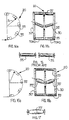
- straight cylindrical rolls 35 when assembled with a relatively large angle ⁇ , will generate in a quadrant roll conveyor two TORO-cylindrical surfaces as shown in Fig. 14b.
- the straight cylindrical rolls 35 may be crowned in accordance with the present invention to generate a perfect straight cylindrical surface as shown, for example, in Fig. 16b.
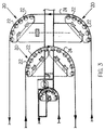
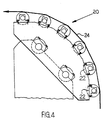
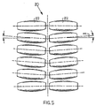
- Figs. 3-5 generally show quadrant roll conveyors 20 made in accordance with the present invention.
- the quadrant roll conveyors 20 shown in Fig. 3 include a 180° quadrant roll conveyor 20 defining a semicircular quadrant arc or semicircular quadrant roll and two (2) 90° quadrant roll conveyors 20 each defining a 90° quadrant arc or quadrant roll.
- the terms "quadrant arc” and “quadrant roll” are used interchangeably hereafter to generally refer to the wrapping angle defined by the respective quadrant roll conveyors 20.
- the present invention is not intended to be limited to quadrant roll conveyors 20 that define wrapping angles of 180° or 90° only, but is intended to include quadrant roll conveyors 20 that define any desired wrapping angle between 0° and 270°.
- the quadrant roll conveyors 20 are used for the transport of strip material, such as metal strip, along a conveying path and to change its direction of travel. These units may replace known steering roll units. Examples of typical conveyor applications for the quadrant roll conveyors 20 include galvanizing lines, pickling lines and the like in continuous strip processing plants.
- the quadrant roll conveyors 20 usually have a plurality of rolls 22 arranged in a semicircular (180°) arc or quadrant (90°) arc configuration such that the surfaces of the rolls 22 define the wrapping angle around which a strip 24 travels. In contrast to the horizontal roll conveyors previously discussed in which the weight of the strip 24 is carried by the horizontal rolls, in the quadrant roll conveyors 20, tension in the strip 24 is balanced by the action of the rolls 22, as is known in the art.
- a unitary steering roll 26, shown schematically in Figs. 6-8 has generally been provided for these purposes.
- the quadrant roll conveyors 20, shown schematically in Figs. 9-11 and made in accordance with the present invention, are intended to replace the unitary steering rolls 26 shown in Figs. 6-8, respectively.
- the unitary steering rolls 26 of the prior art require costly tilting mechanisms (not shown) with associated sensors and controls to maintain the strip 24 in a centered mode of travel.
- the quadrant roll conveyors 20 of the present invention eliminate the need for these costly prior art devices.
- the rolls 22 are positioned to left and right sides 28, 29 of a centerline A-A of the conveyor 20.
- the rolls 22 each have ends journaled in two of three substantially parallel support meters 30, 30' and 30''.
- the support meter 30' is positioned in the center of the conveyor 20 and is preferably coaxial with the centerline A-A thereof.
- the rolls 22 each define an angle ⁇ with the conveyor centerline A-A. The angle ⁇ is less than 90° and, thus, the rolls 22 are arranged in the herringbone or chevron configuration previously discussed.
- the rolls 22 are not driven. However, driven rolls 22 may be provided in the conveyor 20.
- the rolls 22 are positioned on the left and right sides 29, 29 of the conveyor centerline A-A such that the rolls 22 each have an axis of rotation intersecting the axis of rotation of the corresponding roll 22 located on the opposite side of the conveyor centerline A-A.
- the axes of rotation of each pair of oppositely facing rolls 22 intersect at a point located on the conveyor centerline A-A. More particularly, each pair of oppositely positioned rolls 22 has axes of rotation that intersect at a point located in a vertical plane passing through the conveyor centerline A-A and the central roll support member 30'.
- a staggered chevron arrangement for the rolls 22 is also envisioned by the present invention. In this embodiment (not shown), the axes of rotation of oppositely positioned rolls 22 do not intersect.
- Metal strip may be positioned on the surface of the rolls 22 and carried thereby.
- the conveyor 20, with the rolls 22 forming the angle ⁇ with the conveyor centerline A-A, provides better centering action then the herringbone arrangement previously discussed in connection with horizontal roll conveyors, but over a semicircular (180°) arc or quadrant (90°) arc rather than in a horizontal plane. Additionally, the conveyor 20 is able to deflect the strip 24 in the manner previously discussed in connection with the deflector rolls 26, shown in Figs. 6-8.
- the herringbone or chevron configuration previously described has not been extended beyond its application in horizontal roll conveyors because as the straight cylindrical rolls 22 shown in Figs. 12 and 13 are assembled with smaller angles ⁇ , the surfaces of the straight cylindrical rolls 22 no longer define a flat semicircular or quadrant arc, i.e., a flat surface profile around the arc.
- the surface of the conveyor 20 no longer equates to the relatively straight profile defined by the surface of a cylindrical deflector roll, as shown in Figs. 6-8.
- the surface of the conveyor 20 with straight cylindrical rolls will be equivalent to a cylindrical deflector roll with a surface profile defined by two (2) TORO edges as shown in Fig. 14b.
- Fig. 15 shows typical straight cylindrical rolls 35 that are generally used in horizontal roll conveyors.
- the present invention overcomes also the inherent disadvantages of the straight cylindrical rolls 35 when used in the conveyor 20 by substituting the straight cylindrical rolls 35 with profiled rolls 35', 35'' shown in Figs. 16-18 in the herringbone or chevron configuration of the conveyor 20.
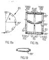
- Figs. 16 and 17 show profiled rolls 35' in accordance with the present invention that are crowned in the longitudinal direction.
- the crowned rolls 35' generate a straight cylindrical profile when applied in the herringbone arrangement in the conveyor 20.
- the degree of crowning C for the rolls 35' is a function of the angle ⁇ .
- C R (1 - cos(arcsin ( L 2R sin ⁇ ))), wherein ⁇ is the complementary angle to the angle ⁇ that is defined between the conveyor centerline A-A and the respective roll 35' centerline or axis of rotation; wherein L is a distance between the conveyor centerline A-A and one of the support members 30, 30''; and wherein R is a radius of the quadrant roll conveyor 20 as shown in Figs. 9-11.
- Figs. 18 and 19 show profiled rolls 35'' with crowning only on a central part of the profiled rolls 35''. With this type of crown, it is possible to have a flat or straight cylindrical profile in the center of a conveyor 101 and TORO profiles on edges 102. As shown in Fig. 19, a first portion of the roll 35'' is cylindrical and a second portion of the roll 35'' is tapered or crowned. This design will increase the strip centering effect and generate more pressure and centering forces when a strip (not shown) is "walking" out of center on the conveyor 101.
- the conveyor 20, preferably having rolls 35' or rolls 35'', is used to convey strip material as discussed hereinafter.
- the strip 24 is positioned onto the rolls 22 such that the strip 24 contacts the surfaces of the rolls 22.
- the rolls 22 are not driven.
- the strip 24 is generally located between the outer support members 30, 30'' and is under tension to place the strip 24 firmly in contact with the surfaces of the rolls 22.
- the tension in the strip 24 preferably provides motive forces to the strip 24 causing the strip 24 to move in a conveying direction, indicated by arrows in Fig. 10.
- the tension in the strip 24 and the frictional interaction between the strip 24 and the surfaces of the rolls 22 cause the rolls 22 to rotate.
- the tensioned strip 24 moves along the surfaces of the rotating rolls 22 and in the conveying direction around the semicircular or quadrant arc defined by the conveyor 20.
- the quadrant arc is a 180° arc. Due to the herringbone or chevron orientation of the rolls 22, the strip 24 is centered to the centerline A-A of the conveyor 20 as the strip 22 traverses around the semicircular arc defined by the rolls 22.
- the quadrant arc or quadrant roll is not limited to a wrapping angle of between 90° and 180° and can be any desired wrapping angle.
- the quadrant roll conveyor 20 With the quadrant roll conveyor 20 according to the present invention, it is possible to replace existing prior art steering/centering rolls that are activated with an electro-hydraulic unit. No electro-hydraulic unit is necessary and the related installation and maintenance costs are significantly reduced by the present invention.
- the quadrant roll conveyor 20 made according to the present invention provides strip centering action to strip material around an "arc" or "roll” of any desired wrapping angle. Additionally, it is not intended to limit the present invention to the transport of metal strip, but relates to the transport of strip material generally.
Landscapes
- Registering, Tensioning, Guiding Webs, And Rollers Therefor (AREA)
- Treatment Of Fiber Materials (AREA)
- Packaging Of Special Articles (AREA)
Applications Claiming Priority (4)
| Application Number | Priority Date | Filing Date | Title |
|---|---|---|---|
| US459231 | 1989-12-29 | ||
| US11848299P | 1999-02-03 | 1999-02-03 | |
| US118482P | 1999-02-03 | ||
| US09/459,231 US6457623B1 (en) | 1999-02-03 | 1999-12-10 | Roll quadrant with strip centering action |
Publications (2)
| Publication Number | Publication Date |
|---|---|
| EP1026112A2 true EP1026112A2 (de) | 2000-08-09 |
| EP1026112A3 EP1026112A3 (de) | 2002-07-03 |
Family
ID=26816415
Family Applications (1)
| Application Number | Title | Priority Date | Filing Date |
|---|---|---|---|
| EP00101682A Withdrawn EP1026112A3 (de) | 1999-02-03 | 2000-02-02 | Rollenquadrant mit Bahnzentrierungsfunktion |
Country Status (2)
| Country | Link |
|---|---|
| US (1) | US6457623B1 (de) |
| EP (1) | EP1026112A3 (de) |
Families Citing this family (5)
| Publication number | Priority date | Publication date | Assignee | Title |
|---|---|---|---|---|
| FR2840827B1 (fr) * | 2002-06-13 | 2004-08-27 | Vai Clecim | Dispositif de guidage d'un produit en bande |
| JP5243305B2 (ja) * | 2009-03-02 | 2013-07-24 | ユニ・チャーム株式会社 | ウェブ搬送装置及び吸収性物品の製造方法 |
| KR101832142B1 (ko) * | 2017-08-22 | 2018-02-27 | 화동하이테크 주식회사 | 물류 자동 정렬 및 이송 컨베어 장치 |
| US20230166915A1 (en) * | 2021-11-19 | 2023-06-01 | Roach Manufacturing Corporation | Singulating conveyor with different speed zones in a herringbone pattern and method of operation thereof |
| US20240150133A1 (en) * | 2022-11-08 | 2024-05-09 | Roach Manufacturing Corporation | Singulating conveyor with different speed zones in a herringbone pattern and method of operation thereof |
Family Cites Families (17)
| Publication number | Priority date | Publication date | Assignee | Title |
|---|---|---|---|---|
| US1863520A (en) | 1931-08-12 | 1932-06-14 | Walter Wood | Roller conveyer |
| US2593157A (en) * | 1949-06-04 | 1952-04-15 | United States Steel Corp | Apparatus for positioning strip |
| US2592581A (en) | 1950-01-13 | 1952-04-15 | United States Steel Corp | Method and apparatus for positioning strip |
| US2593158A (en) * | 1950-02-23 | 1952-04-15 | United States Steel Corp | Apparatus for positioning strip |
| US2692773A (en) | 1951-03-08 | 1954-10-26 | United States Steel Corp | Automatic self-centering roll |
| US2682333A (en) * | 1951-11-23 | 1954-06-29 | United States Steel Corp | Roller conveyer |
| US2828852A (en) * | 1955-12-27 | 1958-04-01 | United States Steel Corp | Roller conveyor |
| FR1191028A (fr) | 1957-02-08 | 1959-10-16 | Siemag Siegener Masch Bau | Transporteur à rouleaux, notamment transporteur de stockage pour laminoirs |
| US3218000A (en) * | 1963-02-18 | 1965-11-16 | Wilson Eng Co Inc Lee | Strip handling apparatus |
| US3331542A (en) * | 1964-04-22 | 1967-07-18 | Colifeed Systems Inc | Threading rail means for strip stock feeding apparatus |
| DE2107977C3 (de) | 1971-02-19 | 1975-11-06 | Maschinenbau Oppenweiler Binder & Co, 7157 Oppenweiler | Fördertisch zum Fördern und Ausrichten von Bogen |
| GB1359027A (en) * | 1971-12-03 | 1974-07-03 | British Iron Steel Research | Apparatus for guiding sheet metal |
| DE3217762A1 (de) * | 1982-05-12 | 1983-12-01 | Robert Bosch Gmbh, 7000 Stuttgart | Fuehrungsanordnung fuer ein magnetband |
| US4643013A (en) | 1985-06-25 | 1987-02-17 | Blazevic David T | Coil guide system for hot strip mills |
| DE3826638A1 (de) * | 1988-06-23 | 1989-12-28 | Neckermann Versand Ag | Vorrichtung zum transportieren von waren |
| JP2525293B2 (ja) * | 1990-07-09 | 1996-08-14 | 株式会社ホタニ | 金属ストリップc反り矯正機 |
| JPH06329294A (ja) * | 1993-05-24 | 1994-11-29 | Toshiba Corp | リ−ド・フレ−ム搬送装置 |
-
1999
- 1999-12-10 US US09/459,231 patent/US6457623B1/en not_active Expired - Fee Related
-
2000
- 2000-02-02 EP EP00101682A patent/EP1026112A3/de not_active Withdrawn
Also Published As
| Publication number | Publication date |
|---|---|
| EP1026112A3 (de) | 2002-07-03 |
| US6457623B1 (en) | 2002-10-01 |
Similar Documents
| Publication | Publication Date | Title |
|---|---|---|
| US5655642A (en) | Idler roll for use in belt conveyor systems | |
| EP1049639B1 (de) | Bandzentriervorrichtung | |
| MXPA96001900A (en) | Idler roll for use in belt conveyor systems | |
| US9884730B2 (en) | Apparatus and method for tracking conveyor belts | |
| WO2000003817A1 (en) | Roller leveler | |
| EP1026112A2 (de) | Rollenquadrant mit Bahnzentrierungsfunktion | |
| IE62305B1 (en) | System for forming a laminate of dough and fat | |
| US5823464A (en) | Device for guiding ply webs of paper or the like | |
| SE456736B (sv) | Anordning vid bandtransportoerer | |
| US4842130A (en) | Belt bender | |
| US6257964B1 (en) | Roll grinding system for a roll | |
| EP0172027B1 (de) | Bandführungseinrichtung für ein Fördersystem | |
| US9016456B1 (en) | Arcuate roller conveyor | |
| US5743379A (en) | Conveyor belt feed/discharge insert | |
| CA2482316A1 (en) | Web tension equalizing roll and tracking apparatus | |
| CN113993797B (zh) | 用于输送带系统的运载滚轮 | |
| EP1008522A1 (de) | Einwickelvorrichtung | |
| EP0420907A1 (de) | Förderband. | |
| WO2003068638A1 (en) | Conveyor belt training idler roller and installations including same | |
| WO1993006028A1 (en) | Angle station | |
| AU2015303806A1 (en) | Conveyor system for transporting goods with a trough-like conveyor belt and conical drums | |
| US2919793A (en) | Automatic self-centering pulleys for belt conveyors | |
| US5415266A (en) | Conveying apparatus for displacing articles in different directions along a transport surface | |
| US5765679A (en) | Paper transport system | |
| US3195712A (en) | Movable conveyor-type strip for pedestrians |
Legal Events
| Date | Code | Title | Description |
|---|---|---|---|
| PUAI | Public reference made under article 153(3) epc to a published international application that has entered the european phase |
Free format text: ORIGINAL CODE: 0009012 |
|
| AK | Designated contracting states |
Kind code of ref document: A2 Designated state(s): AT BE CH CY DE DK ES FI FR GB GR IE IT LI LU MC NL PT SE |
|
| AX | Request for extension of the european patent |
Free format text: AL;LT PAYMENT 20000211;LV;MK;RO;SI |
|
| PUAL | Search report despatched |
Free format text: ORIGINAL CODE: 0009013 |
|
| RIC1 | Information provided on ipc code assigned before grant |
Free format text: 7B 65H 23/26 A, 7B 65H 23/038 B |
|
| AK | Designated contracting states |
Kind code of ref document: A3 Designated state(s): AT BE CH CY DE DK ES FI FR GB GR IE IT LI LU MC NL PT SE |
|
| AX | Request for extension of the european patent |
Free format text: AL;LT PAYMENT 20000211;LV;MK;RO;SI |
|
| AKX | Designation fees paid |
Designated state(s): AT BE CH CY DE DK ES FI FR GB GR IE IT LI LU MC NL PT SE |
|
| AXX | Extension fees paid |
Extension state: LT Payment date: 20000211 |
|
| STAA | Information on the status of an ep patent application or granted ep patent |
Free format text: STATUS: THE APPLICATION IS DEEMED TO BE WITHDRAWN |
|
| 18D | Application deemed to be withdrawn |
Effective date: 20030104 |