EP1025432B1 - Interlocked high power fiber system using otdr - Google Patents
Interlocked high power fiber system using otdr Download PDFInfo
- Publication number
- EP1025432B1 EP1025432B1 EP97954515A EP97954515A EP1025432B1 EP 1025432 B1 EP1025432 B1 EP 1025432B1 EP 97954515 A EP97954515 A EP 97954515A EP 97954515 A EP97954515 A EP 97954515A EP 1025432 B1 EP1025432 B1 EP 1025432B1
- Authority
- EP
- European Patent Office
- Prior art keywords
- otdr
- high power
- wavelength
- fiber
- optical path
- Prior art date
- Legal status (The legal status is an assumption and is not a legal conclusion. Google has not performed a legal analysis and makes no representation as to the accuracy of the status listed.)
- Expired - Lifetime
Links
- 239000000835 fiber Substances 0.000 title claims abstract description 118
- 230000003287 optical effect Effects 0.000 claims abstract description 117
- 238000000253 optical time-domain reflectometry Methods 0.000 claims abstract description 59
- 238000012544 monitoring process Methods 0.000 claims description 21
- 230000008878 coupling Effects 0.000 claims description 11
- 238000010168 coupling process Methods 0.000 claims description 11
- 238000005859 coupling reaction Methods 0.000 claims description 11
- 238000000034 method Methods 0.000 claims 11
- 238000001914 filtration Methods 0.000 claims 2
- 230000005540 biological transmission Effects 0.000 abstract description 8
- 239000013307 optical fiber Substances 0.000 description 8
- 238000010586 diagram Methods 0.000 description 6
- 238000001069 Raman spectroscopy Methods 0.000 description 3
- 238000004891 communication Methods 0.000 description 3
- 230000006378 damage Effects 0.000 description 3
- 238000001514 detection method Methods 0.000 description 3
- 230000002457 bidirectional effect Effects 0.000 description 2
- 230000000737 periodic effect Effects 0.000 description 2
- 238000005086 pumping Methods 0.000 description 2
- 239000004065 semiconductor Substances 0.000 description 2
- 230000003213 activating effect Effects 0.000 description 1
- 230000003321 amplification Effects 0.000 description 1
- 230000001427 coherent effect Effects 0.000 description 1
- 238000005516 engineering process Methods 0.000 description 1
- 230000007717 exclusion Effects 0.000 description 1
- 230000004927 fusion Effects 0.000 description 1
- 238000009434 installation Methods 0.000 description 1
- 230000002452 interceptive effect Effects 0.000 description 1
- 238000003199 nucleic acid amplification method Methods 0.000 description 1
- 230000010287 polarization Effects 0.000 description 1
- 229910052761 rare earth metal Inorganic materials 0.000 description 1
- 150000002910 rare earth metals Chemical class 0.000 description 1
- 210000001525 retina Anatomy 0.000 description 1
- 208000037974 severe injury Diseases 0.000 description 1
- 230000009528 severe injury Effects 0.000 description 1
Images

Classifications
-
- H—ELECTRICITY
- H04—ELECTRIC COMMUNICATION TECHNIQUE
- H04B—TRANSMISSION
- H04B10/00—Transmission systems employing electromagnetic waves other than radio-waves, e.g. infrared, visible or ultraviolet light, or employing corpuscular radiation, e.g. quantum communication
- H04B10/07—Arrangements for monitoring or testing transmission systems; Arrangements for fault measurement of transmission systems
- H04B10/071—Arrangements for monitoring or testing transmission systems; Arrangements for fault measurement of transmission systems using a reflected signal, e.g. using optical time domain reflectometers [OTDR]
Definitions
- the present invention relates to optical fiber communication systems and more particularly to a safety interlocked high power fiber system using an OTDR.
- Fiber optic technology has evolved significantly since the invention of the laser.
- Semiconductor lasers, fiber and devices have been continuously improved in support of increasingly sophisticated fiber communication systems.
- practical fiber communication systems employed optical power levels less than 10 mW.
- a new generation of lasers and devices are now capable of producing much greater power.
- These high power Class IV lasers can be used individually or in combination to pump rare-earth doped fiber amplifiers and fiber lasers to yield more than a watt of infrared coherent fiber-coupled power.
- the present application claims an in-fiber safety interlock system as in claim 1.
- a high power (Class IV) laser transmits high power optical signals over a fiber system including a terminal (local and accessible, e.g., on shore)portion and an extended (remote and unaccessible, e.g., under sea) portion.
- a plurality of WDM data signals may be transmitted over the fiber system.
- the terminal portion includes a local optical amplifier and the extended portion may include a remote optical amplifier.
- the laser provides pump energy for the optical amplification.
- the laser is interlocked to an optical time domain reflectometer (OTDR) which monitors the integrity of the fiber system, including both the terminal portion and the extended portion.
- OTDR optical time domain reflectometer
- the OTDR monitors the integrity of the optical path by transmitting a periodic or continuous low power (Class I) optical pulse train and monitors the return signal. In this manner, the OTDR can detect path integrity and the presence of any faults in the fiber system, such as fiber breaks or problems with components.
- a control circuit is connected to both the laser and the OTDR.
- the OTDR senses path integrity
- the high power laser source is enabled.
- the OTDR and the control circuit operate to automatically disable (cease to enable) or shut down the laser.
- the present invention provides an in-fiber interlocking system using an OTDR that continuously senses the integrity of the extended fiber system so that the high power laser can be safely employed.
- multiple high power lasers each operating at a different wavelength are connected to a single fiber system, which may include a remote optical amplifier.
- Each laser is separately interlocked to its own sensing OTDR having a unique wavelength.
- Each OTDR is connected to a discriminating bandpass filter so that each OTDR monitors only its own return signal.
- multiple redundant high power lasers are connected to a local amplifier which produces high signal powers in a single fiber system.
- Each laser is interlocked to its own OTDR.
- the path monitored by the OTDRs includes an extended portion of the fiber path which carries high power amplified signals.
- the lasers may operate together or separately. The operation of the lasers may be automatically adjusted or coordinated based on power requirements of the fiber system and whether any of the lasers have been disabled.
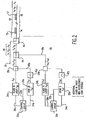
- Fig. 1 illustrates a block diagram of an in-fiber safety interlock system according to a first embodiment of the present invention.
- the safety interlock system 10 includes an optical fiber system 12 including a terminal portion 14 and an extended portion 16 for carrying or transmitting a plurality of optical signals.
- Terminal portion 14 may include a local optical amplifier 15, while extended portion 16 may include a remote optical amplifier 17.
- Amplifiers 15 and 17 may comprise, for example, doped fiber amplifiers or stimulated Raman amplifiers.
- Fiber system 12, for example may be used in a long-haul under sea fiber optic transmission system in which terminal portion 14 is located on-shore and extended portion 16 is located under sea.
- the extended portion 16 of fiber system 12 may extend 40-60 Km or more undersea.
- One or more optical signals each operating at a different wavelength can be simultaneously transmitted over fiber system 12 using wavelength division multiplexing (WDM).
- WDM wavelength division multiplexing
- a plurality of WDM data signals 18 having wavelengths ⁇ 1 ⁇ 2 ... ⁇ n are carried over data signal path 20.
- Data signals 18 are connected to fiber system 12 by optical coupler 22.
- Signal path 20 and fiber system 12 can be bidirectional. The present invention can also operate with alternative optical fiber arrangements.
- Safety interlock system 10 also includes a high power (Class IV) laser 24 transmitting high power at a wavelength ⁇ p .
- Laser 24 can be used as a pump laser to pump optical energy to optical amplifiers 15 and/or 17 within fiber system 12 to amplify data signals 18.
- An optical time-domain reflectometer (OTDR) 26 monitors the continuity or integrity of an optical path which can include the fiber extending from the output of OTDR 26 and fiber system 12 (including terminal portion 14 and extended portion 16). OTDR 26 monitors the continuity or integrity of the optical path by transmitting a periodic or continuous low power optical pulse train at wavelength ⁇ s and monitoring the small fraction of light at wavelength ⁇ s that is scattered back to OTDR 26.
- detection, threshold and/or comparison circuitry within OTDR 26 detect the continuity or integrity of the optical fiber path of the system and/or significant changes in path continuity, or of a certain length of the optical fiber path.
- OTDR 26 can detect the continuity or integrity and/or changes in continuity of the optical path extending out to end point 38. As a result, the protection range of interlock system 10 extends only out to end point 38.
- OTDR 26 may comprise a simplified OTDR having only a subset of the features or capabilities present on most off-the-shelf OTDRs to reduce the expense of the system.
- commercially available OTDRs typically include many features and capabilities, the present invention may only require an OTDR having the ability to determine the integrity of an optical path of a specified distance. Some aspects of the present invention may also require (or benefit from) the OTDR to also identify the location of any faults or fiber breaks detected in the system.
- Optical coupler 28 is connected by fiber to laser 24, OTDR 26 and coupler 22 and combines the optical signals transmitted by laser 24 ( ⁇ p ) and OTDR 26 ( ⁇ s ). Coupler 22 combines the OTDR output signal ( ⁇ s ), the laser output signal ( ⁇ p ), and data signals 18 ( ⁇ 1 ⁇ 2 . .. ⁇ n ) for transmission over fiber system 12. Each of these signals has a different wavelength.
- Control circuit 30 is connected to laser 24 and OTDR 26 for selectively enabling or disabling laser 24 based on information received from OTDR 26.
- Control circuit 30 may comprise a microprocessor and/or other circuitry.
- a "test distance" input 32 from control circuit 30 indicates to OTDR 26 the distance of the optical path that should be monitored.
- OTDR 26 can perform a built-in self test and outputs an "OTDR OK" signal over output 34 to indicate that the OTDR is working properly.
- the detection and threshold circuitry of OTDR 26 detects the presence or absence of continuity or integrity and/or significant changes in optical path losses of the optical path extending from OTDR 26 a distance specified by the "test distance” input 32, and outputs a "clear-path present/absent" signal on output 34.
- Control circuit 30 enables laser 24 by outputting a "laser enable” signal over output 36 only when OTDR 26 is working properly (based on state of "OTDR OK” signal) and OTDR 26 has confirmed the integrity or continuity of the optical path (based on state of "clear-path present/absent” signal). Otherwise, control circuit 30 disables or shuts down laser 24 by outputting a "laser disable” signal over output 36.
- in-fiber safety interlock system 10 may be understood with reference to Fig. 1.
- High power laser 24 is interlocked to OTDR 26 via control circuit 30.
- the OTDR Prior to activating laser 24, the OTDR must be self tested and the integrity of the fiber path of the system must be confirmed to avoid harmful laser emissions from a broken fiber or other faults in the system.
- OTDR 26 Prior to operation and/or during its operation, OTDR 26 performs a built-in self test. If the OTDR fails its built in self test, a signal is output over output 34 from OTDR 26 to control circuit 30 to indicate that OTDR 26 is not working properly. Control circuit then outputs a "clear-path absent" signal on output 34 to laser 24, thereby disabling (or failing to enable) laser 24 because the faulty OTDR 26 cannot be relied upon to accurately monitor the integrity of the system optical path. Alternatively, control circuit 30 may be eliminated and the "clear-path present/absent" signal on output 34 may be input directly to laser 24.
- OTDR 26 When OTDR 26 passes its built-in self test, OTDR 26 outputs an "OTDR OK" signal over output 34 to control circuit 30 to indicate that OTDR 26 is working properly.
- the "test distance” input 32 is received by OTDR 26 from control circuit 30. As discussed above, the "test distance” input 32 indicates a specific optical path distance which OTDR 26 should monitor.
- OTDR 26 confirms the initial integrity of the specified distance of the optical path of the system, i.e.., the optical path extending from OTDR 26, through couplers 28 and 22, and fiber system 12. To confirm the integrity of the optical path of the system, OTDR 26 transmits a plurality of optical pulses at wavelength ⁇ g along the optical path. Detection and threshold circuitry in OTDR 26 determine the integrity of the optical fiber path based on the return scattering of light at wavelength ⁇ s .
- OTDR 26 In the event that OTDR 26 detects a fiber break or other fault in the optical path, OTDR 26 outputs a "clear-path absent” signal on output 34 to control circuit 30. In response to the "clear-path absent” signal, control circuit 30 outputs a "laser disable” signal on output 36 to disable laser 24.
- OTDR 26 In the event that OTDR 26 confirms the integrity of the optical path (i.e., no breaks or faults detected in the path), OTDR 26 outputs a "clear-path present" signal on output 34 to control circuit 30. In response to the "clear-path present” signal, control circuit 30 outputs a "laser enable” signal on output 36 to enable or activate laser 24.
- OTDR 26 continuously monitors the integrity of the optical path by transmitting a plurality of optical pulses and monitoring the return signals. If at any time OTDR 26 detects a fiber break or other fault anywhere in the optical path (including extended portion 16), OTDR 26 immediately outputs a "clear-path absent" signal over output 34. In response, control circuit 30 outputs a "laser disable” signal over output 36 to disable laser 24. In this manner, high power laser 24 is interlocked to an optical path monitoring OTDR 26 and control circuit 30 for automatically shutting down or disabling laser 24 immediately after a fiber break or other fault is detected in the optical path.
- the wavelength ⁇ s of OTDR 26 should be selected to be significantly less that the wavelength ( ⁇ p ) of high power laser 24 to minimize Raman crosstalk and non-linear coupling in extended portion 16 of fiber system 12.
- a wavelength ( ⁇ s ) for OTDR 26 may be chosen to be 1310 nm or 1360 nm to minimize non-linear coupling.
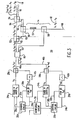
- Fig. 2 illustrates a block diagram of an in-fiber safety interlock system according to a second embodiment of the present invention.
- the in-fiber interlock system 40 illustrated in Fig. 2 includes a plurality of high power (Class IV) laser sources 24a, 24b transmitting over a fiber system 12.
- Fiber system includes terminal portion 14 and extended portion 16.
- a first laser 24a operates at a wavelength ⁇ p1
- the second laser 24b operates at a wavelength ⁇ p2 .
- Each of lasers 24a and 24b is interlocked to its own optical path monitoring OTDR, OTDRs 26a and 26b, respectively.
- the first OTDR 26a operates at a wavelength ⁇ s1
- the second OTDR 26b operates at a wavelength ⁇ s2 .
- a first control circuit 30a is connected to first OTDR 26a and first laser 24a for selectively enabling or disabling first laser 24a based on information received from first OTDR 26a.
- a second control circuit 30b is similarly connected to a second OTDR 26b and second laser 24b for selectively enabling or disabling second laser 24b based on information received from second OTDR 26b.
- An optical bandpass filter 42a is connected to the output path of the first OTDR 26a and passes only the wavelength ( ⁇ s1 ) output by the first OTDR 26a, and rejects other wavelengths. Bandpass filter 42a ensures that first OTDR 26a will sense only its own return signal ( ⁇ s1 ) by rejecting all other wavelengths including the return signal from the second OTDR 26b ( ⁇ s2 ).
- a second bandpass filter 42b is connected to the second OTDR 26b and similarly passes only the wavelength ( ⁇ s2 ) of the second OTDR 26b. Bandpass filter 42b ensures that second OTDR 26b will sense only its own return signal ( ⁇ s2 ). In this manner, bandpass filters 42a and 42b allow multiple OTDRs 26a and 26b operating at different wavelengths to monitor the same (or a common) optical path without interfering with each other.
- optical coupler 28a combines the signal ⁇ p1 output by first laser 24a and the signal ⁇ s1 output by first OTDR 26a.
- optical coupler 28b combines the output of the second laser 24b and the output of the second OTDR 26b.
- additional high power lasers, OTDRs and associated control circuits and bandpass filters may be connected to the in-fiber interlock system 40 of Fig. 2.
- Optical coupler 44 combines the signal ( ⁇ p1 ⁇ s1 ) from the first laser 24a and first OTDR 26a with the signal ( ⁇ p2 ⁇ s2 ).
- An optical coupler 46 combines the signals from the plurality of OTDRs and lasers ( ⁇ p ⁇ s ) with the one or more WDM data signals 18 having wavelengths ⁇ 1 ⁇ 2 ... ⁇ n carried over signal path 20 for transmission over fiber system 12.
- First OTDR 26a and first laser 24a operate in a manner similar to OTDR 26 and laser 24 described above in the first embodiment.
- First OTDR 26a continuously monitors the integrity of a first optical path including bandpass filter 42a, path 48a, couplers 28a, 44 and 46, terminal portion 14 and extended portion 16 of fiber system 12.
- OTDR 26a and control circuit 30a operate to disable first laser 24a.
- second OTDR 26b continuously monitors the integrity of a second optical path including bandpass filter 42b, path 48b, couplers 28b, 44 and 46, terminal portion 14 and extended portion 16 of fiber system 12. In the event that second OTDR 26b detects a fiber break or other fault in the second optical path, second OTDR 26b and control circuit 30b operate to disable second laser 24b.
- Both OTDRs 26a, 26b simultaneously monitor both a separate (uncommon) fiber portion (path 48a and path 48b, respectively) and a common portion of their respective optical paths (extending through coupler 46, terminal portion 14 and extended portion 16 of fiber system 12).
- first OTDR 26a and first control circuit 30a operate to immediately disable or shut down first laser 24a.
- second laser 24b continues operating because there is no break or fault in the second optical path.
- second OTDR 26b and second control circuit 30b operate to immediately disable or shut down second laser 24b, while first laser 24a continues to operate normally.
- all lasers When a fiber break is detected in any portion of the optical paths that are common to the lasers 24a, 24b, all lasers must be disabled or shut down. If a break exists in a common portion of two or more optical paths, all OTDRs monitoring the common section should detect the break and immediately disable or shut down their respective lasers.. For additional safety, a separate controller or circuitry (not shown) may be connected to all control circuits and OTDRs to ensure that all lasers are disabled when a break is detected on a common portion of the paths by any one of the sensing OTDRs. This separate controller may, therefore, operate to detect a malfunctioning OTDR or other circuitry.
- the wavelengths ( ⁇ s1 ⁇ s2 ) of OTDRs 26a and 26b should be selected to be significantly less than both of the wavelengths ( ⁇ p1 ⁇ p2 ) of high power lasers 24a and 24b to minimize Raman scattering and non-linear coupling in extended portion 16 of fiber system 12.
- the wavelengths ⁇ s1. ⁇ s2 for OTDRs 26a and 26b may be selected as 1310 nm and 1360 nm.
- the wavelength of one of the data signals 18 may be selected as 1555 nm.
- Fig. 3 illustrates a block diagram of an in-fiber safety interlock system 50 according to a third embodiment of the present invention.
- the in-fiber interlock system 50 illustrated in Fig. 2 includes a plurality of high power (Class IV) laser sources 24a, 24b transmitting over a local fiber system including a terminal portion 14 and extended portion 16. Both lasers 24a and 24b operate at the same or similar wavelength ⁇ p .
- Each of lasers 24a and 24b is interlocked to its own optical path monitoring OTDR, OTDRs 26a and 26b, respectively.
- the first OTDR 26a operates at a wavelength ⁇ s1' and the second OTDR 26b operates at a wavelength ⁇ s2 .
- Control circuits 30a and 30b selectively enable or disable lasers 24a and 24b respectively based on information received from OTDRs 26a and 26b respectively.
- the interlock system 50 may also include a monitoring circuit 70 connected to lasers 24a and 24b and control circuits 30a and 30b for monitoring and coordinating the operation of lasers 24a and 24b.
- Coupler 28a combines the output ⁇ p from the first laser 24a with the output ⁇ s1 from the first OTDR 26a.
- Coupler 28b combines the output ⁇ p from the second laser 24b with the output ⁇ s2 from the second OTDR 26b. Because lasers 24a and 24b may operate together or separately, optical coupler 60 operates as an optical splitter/combiner and combines both outputs ⁇ p from lasers 24a and 24b into a single signal and then splits this combined ⁇ p signal across both paths 62 and 63. Coupler 60 also combines the output ⁇ s1 from the first OTDR 26a and the output ⁇ s2 from the second OTDR 26b and outputs this combined signal onto the path 62.
- Optical coupler 52 operates as a splitter/combiner and splits the combined signal ⁇ s1 ⁇ s2 ⁇ p from the output 62, with the signals ⁇ p , ⁇ s1 and ⁇ s2 being output on path 64 and the signal ⁇ p being output on path 65. As a result, optical coupler 52 operates to route sensing signals ⁇ s1 and ⁇ s2 around local amplifier 15 to allow OTDRs 26a and 26b monitor a greater distance of extended portion 16.
- signals ⁇ s1 and ⁇ s2 may be individually routed around optical amplifiers 15 and 17 by inserting two couplers on the paths behind (to the left of) coupler 60.
- Coupler 58 combines the WDM data signals 18 having wavelengths ⁇ 1 ⁇ 2 .. ⁇ n on signal path 66 with the signal ⁇ p on path 63.
- the data signals 18 are amplified by local amplifier 15 in which the signal ⁇ p acts as pump energy for amplifier 15.
- Optical coupler 56 operates as a splitter to split the signals passing through amplifier 15 into the data signals 18 ( ⁇ 1 ⁇ 2.... ⁇ n) and the signal ⁇ p on path 65.
- Two paths are formed for feeding the amplifying signal ⁇ p to amplifier 15.
- a first path extends from coupler 60, path 63 and coupler 58.
- a second path is formed from coupler 60, path 62, coupler 52, path 65 and coupler 56.
- the amplifying signal ⁇ p can be fed to amplifier 15 from both directions.
- Coupler 54 combines data signals 18 ( ⁇ 1 ⁇ 2 .. ⁇ n) from coupler 56 with OTDR signals ⁇ s1 and ⁇ s2 on path 64.
- the combined signal ( ⁇ s1 , ⁇ s2 and ⁇ 1 ⁇ 2... ⁇ n ) is fed to extended portion 16.
- the OTDRs 26a and 26b test the integrity of the optical paths by monitoring the back scattering (return signals) of the transmitted signals ⁇ s1 and ⁇ s2 .
- the transmitted signals ⁇ s2 and ⁇ s2 are bidirectional.
- couplers 60 52, and 54 each operates as both a splitter and a combiner depending on the direction of OTDR signal flow.
- Lasers 24a and 24b are interlocked to OTDRs 26a and 26b, respectively.
- First OTDR 26a monitors a first optical path extending through bandpass filter 42a, path 48a, coupler 28a and a common path for both OTDRs (extending through coupler 60, path 62, coupler 52, path 64, coupler 54, and extended portion 16).
- second OTDR 26b monitors the integrity of a second path extending through bandpass filter 42b, path 48b, coupler 28b and the common path.
- OTDR 26a In the event that the first OTDR 26a detects a fault in the first optical path (even within the extended portion 16), OTDR 26a and control circuit 30a operate to immediately disable or shut down laser 24a. Unless the fault is contained in the common path, second laser 24b need not be disabled and will remain operating.
- second OTDR 26b detects a fault in the second optical path (even within the extended portion 16)
- second OTDR 26b and control circuit 30b operate to immediately disable or shut down laser 24b. In this case, unless the fault is contained in the common path, first laser 24a need not be disabled and will remain operating.
- Lasers 24a and 24b can operate as redundant laser pump sources.
- Laser 24a and laser 24b are each separately capable of simultaneously pumping local amplifier 15. As a result, it is necessary to operate only one laser at a time.
- the enabled laser operates at 100% power.
- both lasers for example, may operate at 50% power.
- both lasers 24a and 24b may simultaneously operate at 100% power to increase the gain of amplifier 15.
- Monitoring circuit 70 such as a microprocessor and/or other circuitry may be used to monitor the output power percentage of each laser 24a and 24b and automatically adjust or coordinate the output power of each laser 24a and 24b.
- Monitoring circuit 70 receives an electrical signal from both lasers 24a and 24b indicating whether each laser is on and the output power of each laser.
- Monitoring circuit 70 may also receive signals from circuits 30a and 30b indicating whether a break or fault has been detected, and the location of the fault.
- both lasers 24a and 24b may be operating at 50% power.
- first OTDR 26a detects a break or fault in the uncommon portion of the first optical path and immediately shuts down first laser 26a.
- Monitoring circuit 70 then controls the second laser 26b and control circuit 30b to increase the power output of second laser 26b to 100% to compensate for the loss of the first laser 26a.
- amplifier 15 is provided with sufficient pump energy despite the fault in the first optical path and disabling of first laser 26a.
- the use of monitoring circuit 70 for monitoring the system and automatically adjusting power output may be similarly applied to the system illustrated in Fig. 2.
- the embodiments of the present invention may employ combiners, splitters, wavelength multiplixers, polarization multiplixers or ratio splitters/combiners where appropriate.
Landscapes
- Physics & Mathematics (AREA)
- Electromagnetism (AREA)
- Engineering & Computer Science (AREA)
- Computer Networks & Wireless Communication (AREA)
- Signal Processing (AREA)
- Optical Communication System (AREA)
- Lasers (AREA)
- Testing Of Optical Devices Or Fibers (AREA)
- Supporting Of Heads In Record-Carrier Devices (AREA)
- Chemical Or Physical Treatment Of Fibers (AREA)
- Remote Monitoring And Control Of Power-Distribution Networks (AREA)
Applications Claiming Priority (3)
| Application Number | Priority Date | Filing Date | Title |
|---|---|---|---|
| US728656 | 1996-10-10 | ||
| US08/728,656 US5966206A (en) | 1996-10-10 | 1996-10-10 | Interlocked high power fiber system using OTDR |
| PCT/US1997/018149 WO1998016017A2 (en) | 1996-10-10 | 1997-10-08 | Interlocked high power fiber system using otdr |
Publications (3)
| Publication Number | Publication Date |
|---|---|
| EP1025432A2 EP1025432A2 (en) | 2000-08-09 |
| EP1025432A4 EP1025432A4 (en) | 2005-06-15 |
| EP1025432B1 true EP1025432B1 (en) | 2007-01-17 |
Family
ID=24927756
Family Applications (1)
| Application Number | Title | Priority Date | Filing Date |
|---|---|---|---|
| EP97954515A Expired - Lifetime EP1025432B1 (en) | 1996-10-10 | 1997-10-08 | Interlocked high power fiber system using otdr |
Country Status (7)
Families Citing this family (39)
| Publication number | Priority date | Publication date | Assignee | Title |
|---|---|---|---|---|
| EP2306604B1 (en) | 1998-07-23 | 2012-09-05 | The Furukawa Electric Co., Ltd. | Optical repeater comprising a Raman amplifier |
| JP2000101513A (ja) * | 1998-09-18 | 2000-04-07 | Nec Corp | 遠隔励起中継器及び遠隔励起中継方法 |
| US6567207B1 (en) * | 1999-05-12 | 2003-05-20 | Corvis Corporation | Optical transmission systems and optical amplifiers for use therein |
| US6507679B1 (en) * | 1999-05-13 | 2003-01-14 | Litton Systems, Inc. | Long distance, all-optical telemetry for fiber optic sensor using remote optically pumped EDFAs |
| EP1102114B1 (en) | 1999-05-31 | 2007-09-12 | The Furukawa Electric Co., Ltd. | Raman amplification method |
| DE19933268A1 (de) * | 1999-07-15 | 2001-01-25 | Siemens Ag | Schaltungsanordnung und Verfahren zum Erkennen von einer Unterbrechung bei einer Lichtwellenleiterstrecke |
| US20050074244A1 (en) * | 2000-01-12 | 2005-04-07 | Nortel Networks Limited | Optimization of a communications system based on identification of an optical member |
| EP1170628B1 (en) * | 2000-01-14 | 2018-08-01 | The Furukawa Electric Co., Ltd. | Raman amplifier |
| JP2001235772A (ja) * | 2000-02-22 | 2001-08-31 | Sumitomo Electric Ind Ltd | ラマン増幅制御装置および光伝送システム |
| US6904157B2 (en) * | 2000-08-10 | 2005-06-07 | Shima System Co., Ltd. | Structure around a speaker unit and applied electric or electronic apparatus thereof |
| US6724524B1 (en) * | 2000-08-18 | 2004-04-20 | Corning Incorporated | Gain control in Raman amplifiers |
| KR100372286B1 (ko) | 2000-08-31 | 2003-02-19 | 엘지전자 주식회사 | 광전송 시스템에서 자동 레이저 차단상태의 가시화 장치및 그 방법 |
| JP2002182253A (ja) * | 2000-12-12 | 2002-06-26 | Sumitomo Electric Ind Ltd | 光源安全装置、ラマン増幅器および光伝送システム |
| EP1229675A3 (en) * | 2001-02-02 | 2004-09-22 | The Furukawa Electric Co., Ltd. | Pump light source for raman amplifier and raman amplifier using the same |
| US6433922B1 (en) | 2001-02-26 | 2002-08-13 | Redc Optical Networks Ltd. | Apparatus and method for a self adjusting Raman amplifier |
| US6636345B2 (en) * | 2001-02-27 | 2003-10-21 | Corning Incorporated | Optical fiber pumping system |
| US6850360B1 (en) * | 2001-04-16 | 2005-02-01 | Bookham, Inc. | Raman amplifier systems with diagnostic capabilities |
| US6807001B1 (en) * | 2001-04-17 | 2004-10-19 | Sycamore Networks, Inc. | Auto shutdown for distributed raman amplifiers on optical communication systems |
| US20020154351A1 (en) * | 2001-04-24 | 2002-10-24 | Feinberg Lee Daniel | Optical network architecture with reduced equipment |
| US20040105136A1 (en) * | 2001-05-08 | 2004-06-03 | Corvis Corporation | Interconnections and protection between optical communications networks |
| US6563979B2 (en) | 2001-06-22 | 2003-05-13 | Dorsal Networks, Inc. | Automatically switched redundant switch configurations |
| US6556319B2 (en) | 2001-05-08 | 2003-04-29 | Dorsal Networks, Inc. | Split redundant trunk architecture using passive splitters and path switching |
| JP4588257B2 (ja) * | 2001-06-27 | 2010-11-24 | 富士通株式会社 | ラマン増幅を用いる光増幅システム |
| US7039067B2 (en) * | 2001-07-30 | 2006-05-02 | Dorsal Networks, Inc. | Methods and systems for hybrid interfaces and architectures for optical communications |
| EP1335508B1 (en) * | 2002-02-11 | 2007-03-07 | Alcatel | Safety procedure for optical fiber systems and according safety interface to carry out such safety procedure |
| DE10217029A1 (de) * | 2002-04-11 | 2003-11-06 | Fraunhofer Ges Forschung | Schutzeinrichtung für eine mit Licht hoher Leistung beaufschlagte Faserleitung |
| US8750702B1 (en) * | 2002-06-21 | 2014-06-10 | Rockstar Consortium Us Lp | Passive optical loopback |
| US7099581B2 (en) * | 2002-08-20 | 2006-08-29 | Red Sky Subsea Ltd. | OTDR arrangement for detecting faults in an optical transmission system on a span by span basis |
| DE10246612A1 (de) * | 2002-10-07 | 2004-04-15 | Marconi Communications Gmbh | Optisches Nachrichten verarbeitendes System, Komponenten und Betriebsverfahren dafür |
| US20050279741A1 (en) * | 2004-06-17 | 2005-12-22 | Arenberg Jonathan W | Laser burn through sensor |
| US7146073B2 (en) * | 2004-07-19 | 2006-12-05 | Quantronix Corporation | Fiber delivery system with enhanced passive fiber protection and active monitoring |
| US7218442B2 (en) * | 2005-03-04 | 2007-05-15 | Jds Uniphase Corporation | Optical communications system with fiber break detection in the presence of Raman amplification |
| US9267330B2 (en) * | 2008-08-20 | 2016-02-23 | Foro Energy, Inc. | Long distance high power optical laser fiber break detection and continuity monitoring systems and methods |
| DE102011089482A1 (de) * | 2011-12-21 | 2013-06-27 | Jenoptik Laser Gmbh | Laser mit überwachter Lichtleitfaserstrecke |
| EP2842243B1 (en) * | 2012-03-06 | 2017-06-07 | Adtran, Inc. | Systems and methods for reducing thermal tails on optical time domain reflectometer (otdr) measurements |
| US9247981B2 (en) | 2013-03-12 | 2016-02-02 | DePuy Synthes Products, Inc. | Laser type fixation member securement device and activation system, and related system and methods |
| US9391695B2 (en) * | 2013-07-10 | 2016-07-12 | Neophotonics Corporation | Optical network communication system with embedded optical time domain reflectometer and method of operation thereof |
| JP6363680B2 (ja) * | 2016-11-16 | 2018-07-25 | ファナック株式会社 | レーザ装置 |
| CN112054839B (zh) * | 2020-08-11 | 2022-06-10 | 武汉光迅科技股份有限公司 | 光纤时域反射仪otdr、测试系统、测试方法及存储介质 |
Family Cites Families (6)
| Publication number | Priority date | Publication date | Assignee | Title |
|---|---|---|---|---|
| US3981562A (en) * | 1974-09-09 | 1976-09-21 | Optical Coating Laboratory, Inc. | Spatial filtering for error detection |
| US3981592A (en) * | 1975-03-31 | 1976-09-21 | The United States Of America As Represented By The Secretary Of The Navy | System for locating breaks in fiber optic filaments |
| JPS5777936A (en) * | 1980-11-01 | 1982-05-15 | Asahi Optical Co Ltd | Safety device for detecting transmission fiber trouble |
| US5270537A (en) * | 1987-08-20 | 1993-12-14 | Santa Barbara Research Center | Laser initiated ordance system optical fiber continuity test |
| US5012087A (en) * | 1989-04-13 | 1991-04-30 | General Electric Company | Fiber optic safety system |
| US5251001A (en) * | 1991-11-18 | 1993-10-05 | Teradyne, Inc. | Reflected optical power fiber test system |
-
1996
- 1996-10-10 US US08/728,656 patent/US5966206A/en not_active Expired - Lifetime
-
1997
- 1997-10-08 JP JP51770998A patent/JP4213219B2/ja not_active Expired - Fee Related
- 1997-10-08 AU AU58945/98A patent/AU5894598A/en not_active Abandoned
- 1997-10-08 DE DE69737269T patent/DE69737269T2/de not_active Expired - Lifetime
- 1997-10-08 CA CA002268003A patent/CA2268003C/en not_active Expired - Fee Related
- 1997-10-08 EP EP97954515A patent/EP1025432B1/en not_active Expired - Lifetime
- 1997-10-08 WO PCT/US1997/018149 patent/WO1998016017A2/en active IP Right Grant
Also Published As
| Publication number | Publication date |
|---|---|
| EP1025432A2 (en) | 2000-08-09 |
| JP2001502421A (ja) | 2001-02-20 |
| CA2268003C (en) | 2008-10-07 |
| CA2268003A1 (en) | 1998-04-16 |
| EP1025432A4 (en) | 2005-06-15 |
| WO1998016017A2 (en) | 1998-04-16 |
| DE69737269D1 (de) | 2007-03-08 |
| JP4213219B2 (ja) | 2009-01-21 |
| DE69737269T2 (de) | 2007-05-24 |
| AU5894598A (en) | 1998-05-05 |
| US5966206A (en) | 1999-10-12 |
| WO1998016017A3 (en) | 1998-06-18 |
Similar Documents
| Publication | Publication Date | Title |
|---|---|---|
| EP1025432B1 (en) | Interlocked high power fiber system using otdr | |
| US6483616B1 (en) | Safe repair of malfunction in optical communication system | |
| US5428471A (en) | Fail-safe automatic shut-down apparatus and method for high output power optical communications system | |
| US6547453B1 (en) | Systems and methods for detecting fault conditions and detecting and preventing potentially dangerous conditions in an optical system | |
| US6681079B1 (en) | Optical fibre monitoring system | |
| EP1006682A2 (en) | Automatic power shut-down arrangement for optical line systems | |
| WO1998016017B1 (en) | Interlocked high power fiber system using otdr | |
| JP2011077808A (ja) | 光伝送システム | |
| US7957643B2 (en) | Method and apparatus for automatically controlling optical signal power in optical transmission systems | |
| US6654513B1 (en) | Path monitoring in optical communication systems | |
| US9264134B2 (en) | Automatic laser shutdown and recovery in response to a link break | |
| US20040032642A1 (en) | Method and system for monitoring distributed raman optical transmission line | |
| CN111788780A (zh) | 光中继器、传输路径光纤监测方法以及光传输系统 | |
| US7864389B2 (en) | Method of controlling optical amplifier located along an optical link | |
| US20070103766A1 (en) | Method for monitoring an optical transmission line by means of an optical amplifier and optical amplifier therefor | |
| JP4018075B2 (ja) | 光ファイバ故障切り分け方法 | |
| JP4225035B2 (ja) | 光増幅中継伝送システムとその監視制御方法 | |
| JP2000236298A (ja) | 自動分散補償回路及びそれを用いた光伝送システム | |
| JPH05284114A (ja) | 光中継器監視装置 | |
| JP2005026899A (ja) | 異常監視機能を有する光中継装置 | |
| JP2000106541A (ja) | 光通信システム | |
| JP2002044023A (ja) | 波長多重光送信装置、及び波長多重光送信方法 | |
| JP2000332329A (ja) | 光出力制御機能付光増幅器 | |
| JPH0730486A (ja) | 光中継装置 |
Legal Events
| Date | Code | Title | Description |
|---|---|---|---|
| PUAI | Public reference made under article 153(3) epc to a published international application that has entered the european phase |
Free format text: ORIGINAL CODE: 0009012 |
|
| 17P | Request for examination filed |
Effective date: 19990510 |
|
| AK | Designated contracting states |
Kind code of ref document: A2 Designated state(s): DE FR GB IT |
|
| A4 | Supplementary search report drawn up and despatched |
Effective date: 20050504 |
|
| RAP1 | Party data changed (applicant data changed or rights of an application transferred) |
Owner name: TYCO TELECOMMUNICATIONS (US) INC. |
|
| GRAP | Despatch of communication of intention to grant a patent |
Free format text: ORIGINAL CODE: EPIDOSNIGR1 |
|
| GRAS | Grant fee paid |
Free format text: ORIGINAL CODE: EPIDOSNIGR3 |
|
| GRAA | (expected) grant |
Free format text: ORIGINAL CODE: 0009210 |
|
| AK | Designated contracting states |
Kind code of ref document: B1 Designated state(s): DE FR GB IT |
|
| REG | Reference to a national code |
Ref country code: GB Ref legal event code: FG4D |
|
| REF | Corresponds to: |
Ref document number: 69737269 Country of ref document: DE Date of ref document: 20070308 Kind code of ref document: P |
|
| ET | Fr: translation filed | ||
| PLBE | No opposition filed within time limit |
Free format text: ORIGINAL CODE: 0009261 |
|
| STAA | Information on the status of an ep patent application or granted ep patent |
Free format text: STATUS: NO OPPOSITION FILED WITHIN TIME LIMIT |
|
| 26N | No opposition filed |
Effective date: 20071018 |
|
| PGFP | Annual fee paid to national office [announced via postgrant information from national office to epo] |
Ref country code: GB Payment date: 20131028 Year of fee payment: 17 Ref country code: DE Payment date: 20131029 Year of fee payment: 17 Ref country code: FR Payment date: 20131017 Year of fee payment: 17 |
|
| PGFP | Annual fee paid to national office [announced via postgrant information from national office to epo] |
Ref country code: IT Payment date: 20131025 Year of fee payment: 17 |
|
| REG | Reference to a national code |
Ref country code: DE Ref legal event code: R119 Ref document number: 69737269 Country of ref document: DE |
|
| GBPC | Gb: european patent ceased through non-payment of renewal fee |
Effective date: 20141008 |
|
| PG25 | Lapsed in a contracting state [announced via postgrant information from national office to epo] |
Ref country code: DE Free format text: LAPSE BECAUSE OF NON-PAYMENT OF DUE FEES Effective date: 20150501 Ref country code: GB Free format text: LAPSE BECAUSE OF NON-PAYMENT OF DUE FEES Effective date: 20141008 |
|
| REG | Reference to a national code |
Ref country code: FR Ref legal event code: ST Effective date: 20150630 |
|
| PG25 | Lapsed in a contracting state [announced via postgrant information from national office to epo] |
Ref country code: FR Free format text: LAPSE BECAUSE OF NON-PAYMENT OF DUE FEES Effective date: 20141031 Ref country code: IT Free format text: LAPSE BECAUSE OF NON-PAYMENT OF DUE FEES Effective date: 20141008 |