EP1024764B1 - Implant prothetique obturateur de canal anatomique, et ensemble d'obturation le comportant - Google Patents
Implant prothetique obturateur de canal anatomique, et ensemble d'obturation le comportant Download PDFInfo
- Publication number
- EP1024764B1 EP1024764B1 EP98947707A EP98947707A EP1024764B1 EP 1024764 B1 EP1024764 B1 EP 1024764B1 EP 98947707 A EP98947707 A EP 98947707A EP 98947707 A EP98947707 A EP 98947707A EP 1024764 B1 EP1024764 B1 EP 1024764B1
- Authority
- EP
- European Patent Office
- Prior art keywords
- implant
- panels
- implant according
- textile element
- radial elements
- Prior art date
- Legal status (The legal status is an assumption and is not a legal conclusion. Google has not performed a legal analysis and makes no representation as to the accuracy of the status listed.)
- Expired - Lifetime
Links
Images

Classifications
-
- A—HUMAN NECESSITIES
- A61—MEDICAL OR VETERINARY SCIENCE; HYGIENE
- A61F—FILTERS IMPLANTABLE INTO BLOOD VESSELS; PROSTHESES; DEVICES PROVIDING PATENCY TO, OR PREVENTING COLLAPSING OF, TUBULAR STRUCTURES OF THE BODY, e.g. STENTS; ORTHOPAEDIC, NURSING OR CONTRACEPTIVE DEVICES; FOMENTATION; TREATMENT OR PROTECTION OF EYES OR EARS; BANDAGES, DRESSINGS OR ABSORBENT PADS; FIRST-AID KITS
- A61F2/00—Filters implantable into blood vessels; Prostheses, i.e. artificial substitutes or replacements for parts of the body; Appliances for connecting them with the body; Devices providing patency to, or preventing collapsing of, tubular structures of the body, e.g. stents
- A61F2/0063—Implantable repair or support meshes, e.g. hernia meshes
- A61F2002/0068—Implantable repair or support meshes, e.g. hernia meshes having a special mesh pattern
-
- A—HUMAN NECESSITIES
- A61—MEDICAL OR VETERINARY SCIENCE; HYGIENE
- A61F—FILTERS IMPLANTABLE INTO BLOOD VESSELS; PROSTHESES; DEVICES PROVIDING PATENCY TO, OR PREVENTING COLLAPSING OF, TUBULAR STRUCTURES OF THE BODY, e.g. STENTS; ORTHOPAEDIC, NURSING OR CONTRACEPTIVE DEVICES; FOMENTATION; TREATMENT OR PROTECTION OF EYES OR EARS; BANDAGES, DRESSINGS OR ABSORBENT PADS; FIRST-AID KITS
- A61F2/00—Filters implantable into blood vessels; Prostheses, i.e. artificial substitutes or replacements for parts of the body; Appliances for connecting them with the body; Devices providing patency to, or preventing collapsing of, tubular structures of the body, e.g. stents
- A61F2/0063—Implantable repair or support meshes, e.g. hernia meshes
- A61F2002/0072—Delivery tools therefor
Definitions
- the present invention relates to an implant prosthetic obturator of channel, cavity or orifice anatomical, and will be more particularly described under example for use in processing groin hernias.
- an implant has been described prosthetic obturator of channel, cavity, or orifice anatomical, comprising a porous textile element, in a single plate, obtained from a prosthetic tissue.
- this porous element in the form of a textile piece with an edge or continuous outer rim. It has several reinforcing radiator elements, intertwined in the room textile, spreading and distributed around an area central free of any said element. These elements of reinforcement determine, by local push in said zone central, while centripetally constraining the remaining periphery of the textile element, a conformation picked up in volume.
- the present invention relates to an implant prosthetic as defined above, having practically no privileged or residual form, therefore maintaining good conformability, while providing nevertheless a certain rigidity during its handling, on the one hand to be introduced in collected form in the anatomical opening to be closed, and secondly for lean in this form against the edge or wall said orifice, all of it in a way that is not or little traumatic.
- the two radiating elements determine at least two opposite hollow lobes, open or closed, formed by the two plates between said elements radiators. This lobed conformation helps consistency of the textile element in its collected conformation.
- Another object of the present invention is a obturation assembly comprising a prosthetic implant as previously described and an installation aid.
- a prosthetic implant according to the invention had the advantage that the non preforming the implant into a cylinder or cone shape favored its congruence with the complex geometry of a orifice, canal or anatomical cavity, for example hernial.
- the radiating elements extend radially each from the outer edge of the element textile to an intermediate point between a center geometric of said textile element and the outer edge of said textile element.
- the radiating elements each extend radially to the central area.
- the elements radials each extend radially over a length limited, from and near the outer edge.
- the two plates are connected to each other by a discontinuous overcasting along the outer edges of the plates, so as to determine lobes open in the collected conformation of the implant.
- the two plates are connected to each other by the radiating elements, bracing said plates.
- the element textile comprises at least three plates linked together, of identical or different nature, one of the plates having possibly a three-dimensional structure.
- the textile element is likely to be obtained by cutting a part circular gathering an outer plate, a plate intermediate, and an inner plate, by folding said part according to a diameter in two sides in opposite, the radiating elements connecting the three plates between them, and at least two elements connecting the two sides facing the inner plate.
- the elements heaters connect two plates to each other, the third plate being connected to the other two by the overcasting of its outer edge.
- the implant has an additional cover plate, linked to the textile element, having a shape different from that last and fitted with a suitable slit to surround all anatomical duct.
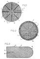
- Figure 1 shows a prosthetic implant shutter 1 according to the present invention, seen in plan of above.
- the prosthetic implant is generally shaped circular, and for example has a diameter of about 8 cm. This shape can of course vary, and we can use for example prosthetic implants of shape elliptical, for example having a diameter included between about 6.5 cm (small diameter), and 8.5 cm (large diameter).
- the obturator prosthetic implant 1 in its conformation not picked up flat, includes one element porous textile, shaped like a piece with an edge outside or around 5 continuous, and is constituted by a plate 2 (upper according to Fig. 1) and a second plate 3 (lower according to Fig. 1), superimposed and each composed of knitted warp and weft threads, relatively flexible prosthetic fabric, for example non-absorbable biocompatible polymer, and preferably base of multi-strand polyester thread 50 dtex.
- a fabric prosthetic is manufactured and marketed by the applicant under the reference PAC, and consists of a knitted fabric with woven chain, square days, made with three layers of chain son. The fabric has good stability bidirectional and cannot be cut when cut.
- the two plates can of course be of the same type or different but usually each have a two-dimensional grid structure, for example with pores of about 1.5 mm x 1.5 mm. As we can see it in figure 1, in relation to the grid of the two-dimensional structure, the two plates can be angularly offset from each other, and the plate 3 is preferably oriented at 45 ° by compared to plate 2.
- radiator elements and plication guide, extending and distributed around a central area 6 free from any said radiant element.
- the elements radials 4 determine, when applying a thrust local, for example with your finger, in the area central 6, and while constraining in a centripetal way the remaining periphery of the textile element 1a, a conformation picked up in volume comprising at least two opposite hollow lobes 32, formed by the two plates 2 and 3 between the radiator elements 4.
- these radiating elements 4 are integrated into the textile element, bracing the two plates, and binding them to each other.
- the plates are elliptical in shape
- the seams radials 4 have unequal lengths, and they converge towards the geometric center 6a of the ellipse, stopping by example about 1 cm from it. So the elements radiators 4 do not extend to the center geometric 6a of the textile element la, but up to the central zone 6, which avoids the risk of perforation or trauma to sensitive organs in or around the orifice or channel to be closed when the implant is in its conformation picked up.
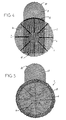
- the obturator prosthetic implant according to FIG. 2 differs from that shown in accordance with Figure 1, in that the textile element comprises it in addition a third plate 7, preferably with structure three-dimensional porous rehabitable, and presenting by example a thickness of about 1.5 to 2 mm.
- a third plate 7 preferably with structure three-dimensional porous rehabitable, and presenting by example a thickness of about 1.5 to 2 mm.
- This plate is marketed by the applicant, under the PAT name.
- This plate is a chain knit three-dimensional spacer, having two faces hexagonal days linked by a thread spacer of chain, and which gives it elasticity three-way.
- the third plate is the one that will rely on the various organs during the repair a direct inguinal hernia for example, and will protect these from possibly traumatic contact with the plates 2 and 3.
- the plates 2 and 3 are secured to the third plate 7 by discontinuous overcasting 8 along of the common circular edge 5 of said plates.
- the thread of overcasting is preferably identical to that used for the radiator elements 4.
- the assembly obtained in accordance with FIG. 2 can be optionally coated with collagen, for example bovine type 1.
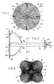
- FIG. 3 illustrates a cover plate complementary for the prosthetic implant according to the invention.
- This plate 9 can have a width about 4.5 cm and a length of about 11 cm, and is generally rectangular in shape. It includes a slot 10, adapted to receive an anatomical conduit, by example the sperm vessels in case of repair hernial, and extending from a straight edge inside 11, or short side of plate 9, preferably perpendicular to the transverse edge 12, or long side of plate 9; the slot 10 extends in the middle of the plate, over a length of about 3 cm. Opposite the edge rounded exterior 11 of cover plate 9 complementary, the latter has another edge exterior 30.
- the additional cover plate 9 is fixed on the textile element 1a, for example by sutures 13, so that the longitudinal axis of symmetry of said plate coincides with a diameter of the textile element circular la, with the inner edge 11 included in the circle defined by said textile element, and the edge outside 30 outside said circle.
- the fixation is advantageously carried out along the circular edge of the textile element la.
- the function of this plate additional overlap is to protect areas peripherals of the hernial opening, potentially fragile, risk of recurrence.
- the invention relates also a shutter assembly comprising an implant prosthetic obturator 1 as described above and a laying aid 14.
- This part of the invention is illustrated by Figures 6 to 9, in which the only difference compared to the prosthetic implant of the figures previous is that the 4 radiator and guide elements of plication, consist of only four seams distributed radially around the center geometrical 6a of the obturator implant, and extending over a shorter distance to the central area 6.
- a fitting aid 14 may consist of a rigid tubular element 15, for example a rigid cannula, in which a thread 16 has passed tensile, the wire 16 being freely interlaced in the plate 2 of the textile element 1, so that the ends of the wire 16, as well as a loop 17 formed of the wire 16 protrude from the open proximal end 15b of the tubular element 15.
- the wire 16 comes out of the element tubular 15 by openings 23a, 23b at a distance from the open distal end 15a of the tubular element 15, this distance corresponding for example at least to the distance between the geometric center 6a of the element textile from its outer edge 5, for example to at minus 4 cm (radius of the circle of the prosthetic implant shutter).
- the wire 16 passes from an opening 23a towards the outer edge 5 according to reference 16a, and around a warp or weft thread at a location 20a on the plate 2, to return according to reference 16b towards a diametrically opposite place 20b to that previously described, either by going back to the openings 23a and 23b, either directly according to reference 16c to return then towards the openings 23a, 23b according to the reference 16d.
- This operation is repeated with the same wire 16 according to references 16e, 16f, 16g and 16h, aux places 21a, 21b, so as to form a cross pattern; cf. figure 6.
- the prosthetic implant shutter 1 has a rosette shape, ready to introduction into the anatomical canal, orifice or cavity, by the surgeon.
- the installation instrument therefore allows with a single wire, for example looped, to pick up the obturator prosthetic implant 1 around the axis of the tubular element 15 by simple traction.
- the withdrawal of wire 16 is made by pulling the loop 17 and thus releases the implant in its site.
- This ancillary decreases the contact of the surgeon's fingers with the body, as well as with the implant, and allows to reach sites not accessible by finger alone.
- each hollow lobe 32 is delimited between a quarter-circle section of the first plate 2, of external convex shape, and a opposite section in quarter of the second plate 3, of concave interior shape, these sections being joined by two radiating elements 4, each common to two adjacent lobes 32.
- the four lobes 32 determine between them an internal cross shape.
- FIGs 10 and 11 show another mode preferred execution of the obturator prosthetic implant according to the invention. This other mode will be described only compared to the differences with the modes of execution of Figures 1 to 5.
- the obturator implant 24 has a shape semi-circular, in its shape not collected flat, and the textile element 1a is obtained by cutting a piece circular gathering three plates, interior 2, intermediate 3, and external 7 respectively. This piece is folded in two opposite sides according to a diameter d of the textile element la, so as to form a Semi circle.
- the three plates are connected by radiating elements 4, and the intermediate plates 3 and outer 7 connected to each other by overcasting.
- the inner plate 2 however, has at least two elements, for example seams 25,26 connecting its two opposite sides (see Figure 11).
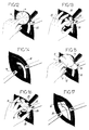
- the prosthetic implant shutter 1 When in use, the prosthetic implant shutter 1 is presented next to the channel or the orifice, for example inguinal, as shown schematically in Figures 12 to 17.
- the reference 35 indicates the spermatic cord.
- the implant is introduced into the orifice or channel by pressing on the area central 6 or the geometric center 6a of plate 2 of the textile element la using a finger, pliers or of the installation instrument.
- the implant passes, through the bias of a centripetal constraint on the remaining periphery of the textile element, which can be exercised for example through the walls of the inguinal opening, from the conformation to flat towards a conformation picked up in volume, such as illustrated by Figures 13, 14 and 16 in particular.
- a prosthetic implant according to the invention "molds" onto anatomical structures in relationship with the orifice or channel to be closed, and forms at minus two opposite hollow lobes 32, the elements radials 4 guiding plication and formation of lobes, and also giving the obturator implant a some radial resistance for better hold mechanical once implanted.
- Figures 15 to 17 show the application of the implant according to FIGS. 3 to 5, which does not differ from this which precedes that in that the complementary plate of cover 9 is positioned above the element textile there, so as to cover an anatomical area around the inguinal opening, to prevent possible recurrences, the slot 10 surrounding the vessels spermatic 35, as can be seen in FIG. 17.
Description
- l'implant prothétique obturateur est traumatisant ou perforant vis à vis des structures péritonéales et ne peut s'adapter que difficilement à l'épaisseur de la paroi abdominale ;
- les formes en cône ou en cylindre de l'implant prothétique ne favorisent pas sa congruence à la géométrie complexe d'un orifice herniaire ;
- les implants prothétiques obturateurs sont soumis à un contact important avec les mains du chirurgien, augmentant ainsi le risque d'une infection post-opératoire ;
- les implants prothétiques obturateurs préformés traditionnels ne permettent pas au chirurgien d'atteindre des sites non accessibles au doigt.
- c'est dans l'élément textile que s'inscrivent et sont compris en continuité, et la zone centrale exempte de tout élément radiaire, et la zone périphérique qui comporte ces éléments radiaires ; la zone centrale est donc comblée par l'élément textile lui-même, et n'est donc pas occupée par un autre élément ou pièce, notamment rapporté ;
- l'élément textile comporte au moins deux plaques en tissu prothétique superposées ;
- et les deux éléments radiaires ont la forme de deux cordons textiles respectivement, constitués chacun par une multiplicité de points liant, notamment par couture ou tricot, les deux dites plaques, avec au moins un fil.
- la Figure 1 représente une vue en plan d'un implant prothétique obturateur selon l'invention, dans sa conformation non ramassée à plat ;
- la Figure 2 représente une variante de l'implant prothétique de la Figure 1, vue de dessous avec un élément textile présentant trois plaques, dans sa conformation non ramassée à plat ;
- la Figure 3 représente une plaque complémentaire de recouvrement pour l'implant prothétique des Figures 1 et 2 ;
- la Figure 4 représente une vue en plan, dans sa conformation non ramassée, à plat, d'un autre mode d'exécution préféré de l'implant prothétique selon l'invention telle qu'illustrée par les Figures 1 et 2, muni de la plaque complémentaire de la Figure 3 ;
- la Figure 5 représente la vue du dessous de l'implant prothétique selon la Figure 4 ;
- la Figure 6 représente une vue en plan d'un autre mode d'exécution préféré de l'implant prothétique selon l'invention, dans sa conformation non ramassée, à plat, dans un ensemble ancillaire d'obturation ;
- la Figure 7 représente une vue de côté de l'ensemble selon la Figure 6 ;
- la Figure 8 représente une vue en plan de l'implant prothétique de la Figure 7 selon la ligne A-A, après un commencement de plicature de celui-ci vers sa conformation ramassée ;
- la Figure 9 représente une vue en perspective latérale de la Figure 8, après plicature complète de l'implant prothétique dans sa conformation ramassée ;
- la Figure 10 représente une vue en plan d'un implant prothétique selon un autre mode d'exécution selon l'invention ;
- la Figure 11 représente une vue de côté de l'implant prothétique de la Figure 10 ;
- la Figure 12 représente une vue schématique de la manipulation d'un implant obturateur selon les figures 1 et 2 pour obturer un canal inguinal ;
- la Figure 13 représente une vue schématique du pliage de l'implant selon les figures 1 et 2 et son introduction dans le canal inguinal ;
- la Figure 14 représente une vue schématique du canal inguinal obturé avec un implant obturateur selon les figures 1 et 2 ;
- la Figure 15 représente une vue schématique de la manipulation d'un implant obturateur selon les figures 3 à 5 pour obturer un canal inguinal, et protéger contre les récidives ;
- la Figure 16 représente une vue schématique du pliage de l'implant selon les figures 3 à 5 et son introduction dans le canal inguinal ;
- la Figure 17 représente une vue schématique du canal inguinal obturé avec un implant obturateur et une plaque de recouvrement complémentaire selon les figures 3 à 5.
- lorsqu'une troisième plaque de structure tridimensionnelle est présente, en sorte de se situer à l'extérieur de l'implant dans sa conformation ramassée, cette structure tridimensionnelle extérieure est très compliante et douce ; c'est la seule structure au contact des tissus environnants, elle n'est pas traumatisante notamment pour les éléments du cordon spermatique et autorise une très bonne réhabitation ;
- les éléments radiaires, assurant la tenue mécanique de l'implant prothétique obturateur, ne sont pas au contact d'éléments critiques tels que le canal déférent, les vaisseaux spermatiques, iliaques ou fémoraux, les nerfs régionaux ;
- l'arrêt des éléments radiaires au niveau de la zone centrale permet à l'extrémité profonde de l'implant prothétique, dans sa conformation ramassée, une fois en place, de ne pas être traumatisante ou perforante vis à vis des structures péritonéales et de s'adapter à l'épaisseur de la paroi abdominale ;
- dans le mode d'exécution avec troisième plaque de structure tridimensionnelle, toutes les zones potentiellement fragiles sont protégées des récidives (orifice direct dans le cas d'un traitement de hernie indirecte et inversement) par un seul et même implant ;
- dans le mode d'exécution avec plaque de recouvrement complémentaire, solidaire de l'élément textile, la fixation aux tissus périphériques de celle-ci contribue à prévenir les risques de migration profonde dans l'implant prothétique ;
- la porosité très élevée de l'élément textile permet une réhabitation conjonctive à coeur pontant l'espace et comblant ainsi de façon stable l'orifice ;
- dans le mode d'exécution avec troisième plaque de structure tridimensionnelle, le surfilage permet avantageusement de ne pas écraser la plaque supérieure sur les plaques inférieures comme l'aurait fait une couture classique, et ainsi de préserver la structure tridimensionnelle compliante sur toute la surface extérieure utile de l'implant.
Claims (12)
- Implant prothétique obturateur (1) de canal, de cavité ou d'orifice anatomique, comprenant un élément textile (1a) poreux, obtenu à partir d'un tissu prothétique, ayant dans une conformation à plat, non ramassée, la forme d'une pièce avec un bord ou pourtour extérieur (5) continu, et ledit élément comportant au moins deux éléments (4) radiaires, s'étendant et distribués autour d'une zone centrale (6) exempte de tout élément radiaire, et lesdits éléments radiaires déterminant, par poussée locale dans ladite zone centrale (6), tout en contraignant de manière centripète le pourtour restant de l'élément textile (1a), une conformation ramassée en volume, caractérisé en ce que, en combinaison, d'une part l'élément textile (1a) dans lequel s'inscrivent en continuité, et ladite zone centrale, et une zone périphérique comprenant lesdits éléments radiaires, comporte au moins deux plaques (2,3) en tissu prothétique superposées, et d'autre part les deux éléments (4) radiaires ont la forme de deux cordons textiles respectivement, constitués chacun par une multiplicité de points liant les deux plaques (2,3) avec au moins un fil.
- Implant selon la revendication 1, caractérisé en ce que, dans la conformation ramassée, les deux éléments radiaires (4) déterminent au moins deux lobes (32) creux opposés, ouverts ou fermés, formés par les deux plaques (2,3) entre lesdits éléments radiaires (4).
- Implant selon la revendication 1, caractérisé en ce que les éléments radiaires (4) s'étendent radialement chacun depuis le bord extérieur (5) de l'élément textile jusqu'à un point intermédiaire entre un centre géométrique (6a) dudit élément textile et le bord extérieur (5) dudit élément textile.
- Implant selon la revendication 1, caractérisé en ce que les éléments radiaires (4) s'étendent chacun radialement jusqu'à la zone centrale (6).
- Implant selon la revendication 3, caractérisé en ce que les éléments radiaires (4) s'étendent chacun radialement sur une longueur limitée à partir de et au voisinage du bord extérieur (5).
- Implant selon la revendication 1, caractérisé en ce que les deux plaques (2,3) sont reliées l'une à l'autre par un surfilage (8) discontinu le long des bords extérieurs (5) des plaques.
- Implant selon la revendication 1, caractérisé en ce que les éléments (4) radiaires entretoisent les plaques (2,3).
- Implant selon la revendication 1, caractérisé en ce que l'élément textile (1a) comprend au moins trois plaques (2,3,7) liées entre elles, de nature identique ou différente, l'une des plaques ayant éventuellement une structure tridimensionnelle.
- Implant selon la revendication 8, caractérisé en ce que l'élément textile (1a) est susceptible d'être obtenu par découpe d'une pièce circulaire rassemblant une plaque extérieure (7), une plaque intermédiaire (3), et une plaque intérieure (2), par pliage de ladite pièce selon un diamètre (d) en deux flancs en vis-à-vis, des éléments (4) radiaires reliant les trois plaques entre elles, et au moins deux éléments (25,26) reliant les deux flancs en vis-à-vis de la plaque intérieure (2).
- Implant selon la revendication 8, caractérisé en ce que les éléments radiaires (4) relient deux plaques l'une à l'autre, la troisième plaque (7) étant reliée aux deux autres (2,3) par le surfilage de son bord extérieur (5).
- Implant selon la revendication 1, caractérisé en ce qu'il comporte une plaque complémentaire (9) de recouvrement, liée à l'élément textile (1a), ayant une forme différente de ce dernier et adaptée avec une fente appropriée pour entourer tout conduit anatomique.
- Ensemble d'obturation de canal, de cavité ou d'orifice anatomique, comprenant un implant obturateur selon l'une quelconque des revendications 1 à 11, et un ancillaire de pose (14).
Applications Claiming Priority (3)
| Application Number | Priority Date | Filing Date | Title |
|---|---|---|---|
| FR9713464A FR2769825B1 (fr) | 1997-10-22 | 1997-10-22 | Implant prothetique obturateur de canal anatomique, et ensemble d'obturation le comportant |
| FR9713464 | 1997-10-22 | ||
| PCT/IB1998/001675 WO1999020204A1 (fr) | 1997-10-22 | 1998-10-21 | Implant prothetique obturateur de canal anatomique, et ensemble d'obturation le comportant |
Publications (2)
| Publication Number | Publication Date |
|---|---|
| EP1024764A1 EP1024764A1 (fr) | 2000-08-09 |
| EP1024764B1 true EP1024764B1 (fr) | 2001-08-22 |
Family
ID=9512705
Family Applications (1)
| Application Number | Title | Priority Date | Filing Date |
|---|---|---|---|
| EP98947707A Expired - Lifetime EP1024764B1 (fr) | 1997-10-22 | 1998-10-21 | Implant prothetique obturateur de canal anatomique, et ensemble d'obturation le comportant |
Country Status (9)
| Country | Link |
|---|---|
| US (1) | US6391060B1 (fr) |
| EP (1) | EP1024764B1 (fr) |
| JP (1) | JP4221149B2 (fr) |
| AT (1) | ATE204445T1 (fr) |
| AU (1) | AU9453998A (fr) |
| DE (1) | DE69801447T2 (fr) |
| ES (1) | ES2163297T3 (fr) |
| FR (1) | FR2769825B1 (fr) |
| WO (1) | WO1999020204A1 (fr) |
Families Citing this family (107)
| Publication number | Priority date | Publication date | Assignee | Title |
|---|---|---|---|---|
| DE19942611C1 (de) * | 1999-08-31 | 2001-07-05 | Ethicon Gmbh | Verstärktes flächiges Implantat |
| US7004970B2 (en) | 1999-10-20 | 2006-02-28 | Anulex Technologies, Inc. | Methods and devices for spinal disc annulus reconstruction and repair |
| US7052516B2 (en) | 1999-10-20 | 2006-05-30 | Anulex Technologies, Inc. | Spinal disc annulus reconstruction method and deformable spinal disc annulus stent |
| US8128698B2 (en) | 1999-10-20 | 2012-03-06 | Anulex Technologies, Inc. | Method and apparatus for the treatment of the intervertebral disc annulus |
| US6592625B2 (en) | 1999-10-20 | 2003-07-15 | Anulex Technologies, Inc. | Spinal disc annulus reconstruction method and spinal disc annulus stent |
| US7935147B2 (en) | 1999-10-20 | 2011-05-03 | Anulex Technologies, Inc. | Method and apparatus for enhanced delivery of treatment device to the intervertebral disc annulus |
| US7615076B2 (en) | 1999-10-20 | 2009-11-10 | Anulex Technologies, Inc. | Method and apparatus for the treatment of the intervertebral disc annulus |
| US8632590B2 (en) | 1999-10-20 | 2014-01-21 | Anulex Technologies, Inc. | Apparatus and methods for the treatment of the intervertebral disc |
| US7951201B2 (en) | 1999-10-20 | 2011-05-31 | Anulex Technologies, Inc. | Method and apparatus for the treatment of the intervertebral disc annulus |
| US6425924B1 (en) * | 2000-03-31 | 2002-07-30 | Ethicon, Inc. | Hernia repair prosthesis |
| US6805695B2 (en) | 2000-04-04 | 2004-10-19 | Spinalabs, Llc | Devices and methods for annular repair of intervertebral discs |
| DE10019604C2 (de) | 2000-04-20 | 2002-06-27 | Ethicon Gmbh | Implantat |
| FR2810536B1 (fr) | 2000-06-23 | 2002-09-27 | Cousin Biotech | Implant textile de reparation |
| US6610006B1 (en) * | 2000-07-25 | 2003-08-26 | C. R. Bard, Inc. | Implantable prosthesis |
| DE10041347A1 (de) * | 2000-08-23 | 2002-03-07 | Ethicon Gmbh | Flächiges Implantat |
| FR2818532B1 (fr) * | 2000-12-22 | 2003-05-30 | Cousin Biotech | Implant prothetique pour orifice anatomique ou chirurgical |
| CA2342641C (fr) * | 2000-12-29 | 2009-03-03 | Ethicon, Inc. | Prothese et methode pour reparer une hernie |
| WO2002056794A2 (fr) * | 2001-01-18 | 2002-07-25 | The Brigham And Women's Hospital, Inc. | Prothese pour patients atteints de troubles respiratoires |
| US6827743B2 (en) * | 2001-02-28 | 2004-12-07 | Sdgi Holdings, Inc. | Woven orthopedic implants |
| US8033983B2 (en) | 2001-03-09 | 2011-10-11 | Boston Scientific Scimed, Inc. | Medical implant |
| US8162816B2 (en) * | 2001-03-09 | 2012-04-24 | Boston Scientific Scimed, Inc. | System for implanting an implant and method thereof |
| US6755868B2 (en) * | 2002-03-22 | 2004-06-29 | Ethicon, Inc. | Hernia repair device |
| EP1581148B1 (fr) | 2002-12-17 | 2010-02-17 | Boston Scientific Limited | Espaceur pour systeme de mise en place d'une attelle |
| GB0300786D0 (en) * | 2003-01-14 | 2003-02-12 | Barker Stephen G E | Laparoscopic port hernia device |
| GB0300784D0 (en) * | 2003-01-14 | 2003-02-12 | Barker Stephen G E | Inguinal hernia repair prosthesis |
| US8926637B2 (en) | 2003-06-13 | 2015-01-06 | Covidien Lp | Multiple member interconnect for surgical instrument and absorbable screw fastener |
| EP1635723B1 (fr) | 2003-06-13 | 2011-08-10 | Tyco Healthcare Group LP | Raccord a elements multiples pour instrument chirurgical et vis resorbable |
| US7361138B2 (en) | 2003-07-31 | 2008-04-22 | Scimed Life Systems, Inc. | Bioabsorbable casing for surgical sling assembly |
| FR2859624B1 (fr) * | 2003-09-16 | 2005-12-02 | Sofradim Production | Tricot prothetique a proprietes variables |
| US8323675B2 (en) * | 2004-04-20 | 2012-12-04 | Genzyme Corporation | Soft tissue prosthesis for repairing a defect of an abdominal wall or a pelvic cavity wall |
| US8298290B2 (en) * | 2004-09-20 | 2012-10-30 | Davol, Inc. | Implantable prosthesis for soft tissue repair |
| KR100675379B1 (ko) * | 2005-01-25 | 2007-01-29 | 삼성전자주식회사 | 프린팅 시스템 및 프린팅 방법 |
| DE102005009356A1 (de) * | 2005-03-01 | 2006-09-07 | Ethicon Gmbh | Chirurgisches Implantat |
| US20060253203A1 (en) * | 2005-05-03 | 2006-11-09 | Alfredo Alvarado | Hernial prosthesis for intraprosthetic fixation |
| US7799079B2 (en) | 2006-01-18 | 2010-09-21 | Zimmer Spine, Inc. | Vertebral fusion device and method |
| AU2007260914B2 (en) * | 2006-06-21 | 2012-11-29 | Cook Biotech Incorporated | Fistula grafts and related methods and systems useful for treating gastrointestinal fistulae |
| US7614258B2 (en) * | 2006-10-19 | 2009-11-10 | C.R. Bard, Inc. | Prosthetic repair fabric |
| US20130190783A1 (en) * | 2007-03-15 | 2013-07-25 | Insighlra Medical, Inc. | Fibrotic band interrupter and implant introducing device |
| US20090024147A1 (en) * | 2007-07-18 | 2009-01-22 | Ralph James D | Implantable mesh for musculoskeletal trauma, orthopedic reconstruction and soft tissue repair |
| US20090187197A1 (en) * | 2007-08-03 | 2009-07-23 | Roeber Peter J | Knit PTFE Articles and Mesh |
| US20090036996A1 (en) * | 2007-08-03 | 2009-02-05 | Roeber Peter J | Knit PTFE Articles and Mesh |
| AU2009215269B2 (en) | 2008-02-18 | 2013-01-31 | Covidien Lp | A device and method for deploying and attaching a patch to a biological tissue |
| US9398944B2 (en) | 2008-02-18 | 2016-07-26 | Covidien Lp | Lock bar spring and clip for implant deployment device |
| US9044235B2 (en) | 2008-02-18 | 2015-06-02 | Covidien Lp | Magnetic clip for implant deployment device |
| US8758373B2 (en) | 2008-02-18 | 2014-06-24 | Covidien Lp | Means and method for reversibly connecting a patch to a patch deployment device |
| US8317808B2 (en) | 2008-02-18 | 2012-11-27 | Covidien Lp | Device and method for rolling and inserting a prosthetic patch into a body cavity |
| US9034002B2 (en) | 2008-02-18 | 2015-05-19 | Covidien Lp | Lock bar spring and clip for implant deployment device |
| US9301826B2 (en) | 2008-02-18 | 2016-04-05 | Covidien Lp | Lock bar spring and clip for implant deployment device |
| US9393002B2 (en) | 2008-02-18 | 2016-07-19 | Covidien Lp | Clip for implant deployment device |
| US9393093B2 (en) | 2008-02-18 | 2016-07-19 | Covidien Lp | Clip for implant deployment device |
| US8808314B2 (en) | 2008-02-18 | 2014-08-19 | Covidien Lp | Device and method for deploying and attaching an implant to a biological tissue |
| US9833240B2 (en) | 2008-02-18 | 2017-12-05 | Covidien Lp | Lock bar spring and clip for implant deployment device |
| US9271706B2 (en) | 2008-08-12 | 2016-03-01 | Covidien Lp | Medical device for wound closure and method of use |
| US20100104608A1 (en) * | 2008-09-26 | 2010-04-29 | Tyco Healthcare Group Lp | Reactive surgical implant |
| US8241654B2 (en) * | 2008-09-26 | 2012-08-14 | Tyco Healthcare Group Lp | Reactive surgical implant |
| US8163022B2 (en) | 2008-10-14 | 2012-04-24 | Anulex Technologies, Inc. | Method and apparatus for the treatment of the intervertebral disc annulus |
| EP2337502B1 (fr) | 2008-10-20 | 2014-08-06 | Covidien LP | Dispositif pour fixer un pansement sur un tissu biologique |
| US20100111919A1 (en) * | 2008-10-31 | 2010-05-06 | Tyco Healthcare Group Lp | Delayed gelation compositions and methods of use |
| DE102008044005A1 (de) * | 2008-11-24 | 2010-05-27 | Leibniz-Institut Für Polymerforschung Dresden E.V. | Flächiges Implantat und Verfahren zu seiner Herstellung |
| FR2945931B1 (fr) * | 2009-06-02 | 2012-07-27 | Jean Claude Sgro | Prothese destinee aux pathologies du type hernie ou eventration |
| US8460350B2 (en) | 2009-06-19 | 2013-06-11 | Arthrex, Inc. | Graft protection mesh and fixation technique |
| AU2010286117B9 (en) | 2009-08-17 | 2014-07-10 | Covidien Lp | Articulating patch deployment device and method of use |
| CA2769666C (fr) | 2009-08-17 | 2018-02-13 | Arie Levy | Moyen et procede pour relier de maniere reversible un implant a un dispositif de deploiement |
| US20110144667A1 (en) * | 2009-09-08 | 2011-06-16 | Anthony Richard Horton | Hernia patch |
| US20110087273A1 (en) * | 2009-10-08 | 2011-04-14 | Tyco Healthcare Group Lp | Wound Closure Device |
| US9833225B2 (en) * | 2009-10-08 | 2017-12-05 | Covidien Lp | Wound closure device |
| US20110087274A1 (en) | 2009-10-08 | 2011-04-14 | Tyco Healtcare Group LP, New Haven, Ct | Wound Closure Device |
| US8617206B2 (en) | 2009-10-08 | 2013-12-31 | Covidien Lp | Wound closure device |
| FR2951069B1 (fr) | 2009-10-09 | 2011-11-18 | Sofradim Production | Element de renfort d'un treillis |
| US8858592B2 (en) * | 2009-11-24 | 2014-10-14 | Covidien Lp | Wound plugs |
| US8652153B2 (en) | 2010-01-11 | 2014-02-18 | Anulex Technologies, Inc. | Intervertebral disc annulus repair system and bone anchor delivery tool |
| MY168863A (en) | 2010-06-17 | 2018-12-04 | Univ Washington | Biomedical patches with aligned fibers |
| FR2968537B1 (fr) * | 2010-12-09 | 2013-04-19 | Sofradim Production | Prothese avec couture en zig-zag |
| FR2972626B1 (fr) | 2011-03-16 | 2014-04-11 | Sofradim Production | Prothese comprenant un tricot tridimensionnel et ajoure |
| US8968760B2 (en) | 2011-04-27 | 2015-03-03 | Covidien Lp | Attachment of a biomaterial to tissue |
| US9750839B2 (en) | 2011-06-30 | 2017-09-05 | Covidien Lp | Drug eluting medical devices |
| FR2977789B1 (fr) * | 2011-07-13 | 2013-07-19 | Sofradim Production | Prothese pour hernie ombilicale |
| FR2977790B1 (fr) | 2011-07-13 | 2013-07-19 | Sofradim Production | Prothese pour hernie ombilicale |
| CA2849052C (fr) | 2011-09-30 | 2019-11-05 | Sofradim Production | Raidissement reversible d'une maille de poids leger |
| US20130156935A1 (en) | 2011-12-14 | 2013-06-20 | Rachit Ohri | Methods for Coating Medical Devices |
| FR2985170B1 (fr) | 2011-12-29 | 2014-01-24 | Sofradim Production | Prothese pour hernie inguinale |
| US9820838B2 (en) | 2012-04-10 | 2017-11-21 | Ethicon, Inc. | Single plane tissue repair patch |
| US9820839B2 (en) | 2012-04-10 | 2017-11-21 | Ethicon, Inc. | Single plane tissue repair patch having a locating structure |
| US9820837B2 (en) | 2012-04-10 | 2017-11-21 | Ethicon, Inc. | Single plane tissue repair patch |
| FR2992547B1 (fr) | 2012-06-29 | 2015-04-24 | Sofradim Production | Prothese pour hernie |
| FR2994185B1 (fr) | 2012-08-02 | 2015-07-31 | Sofradim Production | Procede de preparation d’une couche poreuse a base de chitosane |
| BR112015006301B1 (pt) | 2012-09-21 | 2021-06-15 | Washington University | Sistema para produzir uma estrutura que inclui uma pluralidade de fibras, estrutura e método para reparar um defeito de um substrato |
| FR2995779B1 (fr) | 2012-09-25 | 2015-09-25 | Sofradim Production | Prothese comprenant un treillis et un moyen de consolidation |
| FR2995788B1 (fr) | 2012-09-25 | 2014-09-26 | Sofradim Production | Patch hemostatique et procede de preparation |
| WO2014110209A1 (fr) * | 2013-01-09 | 2014-07-17 | Cook Medical Technologies Llc | Écarteur abdominal |
| US9737294B2 (en) | 2013-01-28 | 2017-08-22 | Cartiva, Inc. | Method and system for orthopedic repair |
| AU2014209124A1 (en) | 2013-01-28 | 2015-09-17 | Cartiva, Inc. | Systems and methods for orthopedic repair |
| US9572559B2 (en) | 2013-03-15 | 2017-02-21 | Covidien Lp | Port site closure |
| FR3004333B1 (fr) * | 2013-04-11 | 2019-08-23 | Biom'up | Prothese implantable de renfort, en particulier pour le renfort de la paroi abdominale |
| US9364311B2 (en) | 2013-12-13 | 2016-06-14 | Covidien Lp | Endoscopic system for winding and inserting a mesh |
| CA2940476C (fr) | 2014-03-06 | 2019-05-07 | C.R. Bard, Inc. | Timbre pour la reparation des hernies |
| US10172700B2 (en) | 2014-12-01 | 2019-01-08 | C.R. Bard, Inc. | Prosthesis for repairing a hernia defect |
| EP3059255B1 (fr) | 2015-02-17 | 2020-05-13 | Sofradim Production | Méthode pour préparer une matrice de chitosane comprenant un élément de renfort fibreux |
| EP3085337B1 (fr) | 2015-04-24 | 2022-09-14 | Sofradim Production | Prothèse pour supporter une structure mammaire |
| ES2676072T3 (es) | 2015-06-19 | 2018-07-16 | Sofradim Production | Prótesis sintética que comprende un tejido de punto y una película no porosa y método para formarla |
| CN108697496B (zh) | 2015-12-28 | 2020-09-04 | C.R.巴德公司 | 用于修复疝缺陷的假体 |
| EP3195830B1 (fr) | 2016-01-25 | 2020-11-18 | Sofradim Production | Prothèse de réparation de hernie |
| US10632228B2 (en) | 2016-05-12 | 2020-04-28 | Acera Surgical, Inc. | Tissue substitute materials and methods for tissue repair |
| EP3312325B1 (fr) | 2016-10-21 | 2021-09-22 | Sofradim Production | Méthode pour la fabrication un treillis avec suture crantée attachée et treillis ainsi obtenu |
| EP3398554A1 (fr) | 2017-05-02 | 2018-11-07 | Sofradim Production | Prothèse pour réparation de hernie inguinale |
| US10624729B2 (en) * | 2017-10-12 | 2020-04-21 | C.R. Bard, Inc. | Repair prosthetic curl mitigation |
| CN111012543A (zh) * | 2019-12-19 | 2020-04-17 | 江南大学 | 一种3d疝修补网及其制备方法 |
Family Cites Families (14)
| Publication number | Priority date | Publication date | Assignee | Title |
|---|---|---|---|---|
| US5141515A (en) * | 1990-10-11 | 1992-08-25 | Eberbach Mark A | Apparatus and methods for repairing hernias |
| US5361752A (en) * | 1991-05-29 | 1994-11-08 | Origin Medsystems, Inc. | Retraction apparatus and methods for endoscopic surgery |
| DE69226841T2 (de) * | 1991-11-05 | 1999-05-20 | Childrens Medical Center | Okklusionsvorrichtung zur Reparatur von Herz- und Gefäss-Defekten |
| DK0544485T3 (da) * | 1991-11-25 | 1995-05-22 | Cook Inc | Indretning til reparation af vævsåbninger |
| DK168419B1 (da) * | 1991-11-25 | 1994-03-28 | Cook Inc A Cook Group Company | Støtteindretning for bugvæg og apparat til indføring heraf |
| US5356432B1 (en) * | 1993-02-05 | 1997-02-04 | Bard Inc C R | Implantable mesh prosthesis and method for repairing muscle or tissue wall defects |
| US5368602A (en) * | 1993-02-11 | 1994-11-29 | De La Torre; Roger A. | Surgical mesh with semi-rigid border members |
| FR2720266B1 (fr) * | 1994-05-27 | 1996-12-20 | Cogent Sarl | Tissu prothétique. |
| US5916225A (en) * | 1994-09-29 | 1999-06-29 | Surgical Sense, Inc. | Hernia mesh patch |
| US5716409A (en) * | 1996-10-16 | 1998-02-10 | Debbas; Elie | Reinforcement sheet for use in surgical repair |
| US5922026A (en) * | 1997-05-01 | 1999-07-13 | Origin Medsystems, Inc. | Surgical method and prosthetic strip therefor |
| US5824082A (en) * | 1997-07-14 | 1998-10-20 | Brown; Roderick B. | Patch for endoscopic repair of hernias |
| US6066776A (en) * | 1997-07-16 | 2000-05-23 | Atrium Medical Corporation | Self-forming prosthesis for repair of soft tissue defects |
| US6241768B1 (en) * | 1997-08-27 | 2001-06-05 | Ethicon, Inc. | Prosthetic device for the repair of a hernia |
-
1997
- 1997-10-22 FR FR9713464A patent/FR2769825B1/fr not_active Expired - Fee Related
-
1998
- 1998-10-21 AT AT98947707T patent/ATE204445T1/de not_active IP Right Cessation
- 1998-10-21 AU AU94539/98A patent/AU9453998A/en not_active Abandoned
- 1998-10-21 ES ES98947707T patent/ES2163297T3/es not_active Expired - Lifetime
- 1998-10-21 WO PCT/IB1998/001675 patent/WO1999020204A1/fr active IP Right Grant
- 1998-10-21 EP EP98947707A patent/EP1024764B1/fr not_active Expired - Lifetime
- 1998-10-21 DE DE69801447T patent/DE69801447T2/de not_active Expired - Lifetime
- 1998-10-21 US US09/529,353 patent/US6391060B1/en not_active Expired - Lifetime
- 1998-10-21 JP JP2000516615A patent/JP4221149B2/ja not_active Expired - Fee Related
Also Published As
| Publication number | Publication date |
|---|---|
| FR2769825B1 (fr) | 1999-12-03 |
| EP1024764A1 (fr) | 2000-08-09 |
| DE69801447D1 (de) | 2001-09-27 |
| AU9453998A (en) | 1999-05-10 |
| US6391060B1 (en) | 2002-05-21 |
| JP4221149B2 (ja) | 2009-02-12 |
| FR2769825A1 (fr) | 1999-04-23 |
| DE69801447T2 (de) | 2001-12-06 |
| JP2001520076A (ja) | 2001-10-30 |
| WO1999020204A1 (fr) | 1999-04-29 |
| ATE204445T1 (de) | 2001-09-15 |
| ES2163297T3 (es) | 2002-01-16 |
Similar Documents
| Publication | Publication Date | Title |
|---|---|---|
| EP1024764B1 (fr) | Implant prothetique obturateur de canal anatomique, et ensemble d'obturation le comportant | |
| EP1100401B1 (fr) | Prothese pour le traitement chirurgical des hernies | |
| EP1083842B1 (fr) | Prothese souple notamment pour la cure des hernies par voie coelioscopique | |
| EP1399101B1 (fr) | Anneau pour gastroplastie | |
| FR2767671A1 (fr) | Dispositif obturateur prothetique pour l'obturation de canaux herniaires | |
| FR2829922A1 (fr) | Implant complet et universel pour la reparation des hernies par voie anterieure | |
| EP2334256B1 (fr) | Instrument chirurgical pour déployer une prothèse | |
| WO1996041588A1 (fr) | Prothese interne sous forme d'un support textile ou autre et son appareil d'insertion par voie coelioscopique | |
| FR2977789A1 (fr) | Prothese pour hernie ombilicale | |
| FR2767672A1 (fr) | Protheses pour l'obturation de canaux herniaires | |
| WO1999027869A1 (fr) | Dispositif pour la mise en place d'une prothese dans le traitement des hernies de l'aine par voie coelioscopique | |
| FR2951069A1 (fr) | Element de renfort d'un treillis | |
| FR2929835A1 (fr) | Attache chirurgicale pour la fixation d'une prothese herniaire | |
| FR2977790A1 (fr) | Prothese pour hernie ombilicale | |
| EP1885279B1 (fr) | Ensemble pour le traitement chirurgical d'un prolapsus et implant adapte pour un tel traitement | |
| CA2909246A1 (fr) | Prothese implantable de renfort, en particulier pour le renfort de la paroi abdominale | |
| FR2778554A1 (fr) | Prothese textile implantable | |
| WO2004012572A2 (fr) | Dispositif d'occlusion d'une ouverture existant dans une paroi corporelle, implantable par voie mini-invasive, et ensemble de mise en place de ce dispositif | |
| EP1625831A1 (fr) | Implant prothetique obturateur | |
| WO2001097713A1 (fr) | Implant textile de reparation | |
| EP2379005B1 (fr) | Dispositif implantable et implant prothetique comprenant au moins un tel dispositif | |
| EP2127614B1 (fr) | Dispositif d'ancrage et de guidage, procédé de fabrication d'un tel dispositif et implant prothétique équipé d'un tel dispositif | |
| FR3121036A1 (fr) | Dispositif pour faciliter l’implantation d’un treillis chirurgical | |
| FR2948011A1 (fr) | Dispositif destine au traitement des hernies et en particulier des hernies ombilicales et eventrations sur trous de trocarts | |
| FR2929836A1 (fr) | Dispositif pour le positionnement, le maintien et la fixation peripherique d'une prothese |
Legal Events
| Date | Code | Title | Description |
|---|---|---|---|
| PUAI | Public reference made under article 153(3) epc to a published international application that has entered the european phase |
Free format text: ORIGINAL CODE: 0009012 |
|
| 17P | Request for examination filed |
Effective date: 20000411 |
|
| AK | Designated contracting states |
Kind code of ref document: A1 Designated state(s): AT BE CH CY DE DK ES FI FR GB GR IE IT LI LU MC NL PT SE |
|
| GRAG | Despatch of communication of intention to grant |
Free format text: ORIGINAL CODE: EPIDOS AGRA |
|
| 17Q | First examination report despatched |
Effective date: 20001208 |
|
| GRAG | Despatch of communication of intention to grant |
Free format text: ORIGINAL CODE: EPIDOS AGRA |
|
| GRAH | Despatch of communication of intention to grant a patent |
Free format text: ORIGINAL CODE: EPIDOS IGRA |
|
| GRAH | Despatch of communication of intention to grant a patent |
Free format text: ORIGINAL CODE: EPIDOS IGRA |
|
| GRAA | (expected) grant |
Free format text: ORIGINAL CODE: 0009210 |
|
| AK | Designated contracting states |
Kind code of ref document: B1 Designated state(s): AT BE CH CY DE DK ES FI FR GB GR IE IT LI LU MC NL PT SE |
|
| PG25 | Lapsed in a contracting state [announced via postgrant information from national office to epo] |
Ref country code: NL Free format text: LAPSE BECAUSE OF FAILURE TO SUBMIT A TRANSLATION OF THE DESCRIPTION OR TO PAY THE FEE WITHIN THE PRESCRIBED TIME-LIMIT Effective date: 20010822 Ref country code: FI Free format text: LAPSE BECAUSE OF FAILURE TO SUBMIT A TRANSLATION OF THE DESCRIPTION OR TO PAY THE FEE WITHIN THE PRESCRIBED TIME-LIMIT Effective date: 20010822 Ref country code: CY Free format text: LAPSE BECAUSE OF NON-PAYMENT OF DUE FEES Effective date: 20010822 Ref country code: AT Free format text: LAPSE BECAUSE OF FAILURE TO SUBMIT A TRANSLATION OF THE DESCRIPTION OR TO PAY THE FEE WITHIN THE PRESCRIBED TIME-LIMIT Effective date: 20010822 |
|
| REF | Corresponds to: |
Ref document number: 204445 Country of ref document: AT Date of ref document: 20010915 Kind code of ref document: T |
|
| REG | Reference to a national code |
Ref country code: CH Ref legal event code: EP |
|
| REF | Corresponds to: |
Ref document number: 69801447 Country of ref document: DE Date of ref document: 20010927 |
|
| REG | Reference to a national code |
Ref country code: IE Ref legal event code: FG4D Free format text: FRENCH |
|
| PG25 | Lapsed in a contracting state [announced via postgrant information from national office to epo] |
Ref country code: MC Free format text: LAPSE BECAUSE OF NON-PAYMENT OF DUE FEES Effective date: 20011021 Ref country code: LU Free format text: LAPSE BECAUSE OF NON-PAYMENT OF DUE FEES Effective date: 20011021 |
|
| PG25 | Lapsed in a contracting state [announced via postgrant information from national office to epo] |
Ref country code: SE Free format text: LAPSE BECAUSE OF FAILURE TO SUBMIT A TRANSLATION OF THE DESCRIPTION OR TO PAY THE FEE WITHIN THE PRESCRIBED TIME-LIMIT Effective date: 20011122 Ref country code: PT Free format text: LAPSE BECAUSE OF FAILURE TO SUBMIT A TRANSLATION OF THE DESCRIPTION OR TO PAY THE FEE WITHIN THE PRESCRIBED TIME-LIMIT Effective date: 20011122 Ref country code: DK Free format text: LAPSE BECAUSE OF FAILURE TO SUBMIT A TRANSLATION OF THE DESCRIPTION OR TO PAY THE FEE WITHIN THE PRESCRIBED TIME-LIMIT Effective date: 20011122 |
|
| REG | Reference to a national code |
Ref country code: CH Ref legal event code: NV Representative=s name: KIRKER & CIE SA |
|
| GBT | Gb: translation of ep patent filed (gb section 77(6)(a)/1977) |
Effective date: 20011117 |
|
| REG | Reference to a national code |
Ref country code: GB Ref legal event code: IF02 |
|
| REG | Reference to a national code |
Ref country code: ES Ref legal event code: FG2A Ref document number: 2163297 Country of ref document: ES Kind code of ref document: T3 |
|
| NLV1 | Nl: lapsed or annulled due to failure to fulfill the requirements of art. 29p and 29m of the patents act | ||
| REG | Reference to a national code |
Ref country code: GR Ref legal event code: EP Ref document number: 20010402199 Country of ref document: GR |
|
| PLBE | No opposition filed within time limit |
Free format text: ORIGINAL CODE: 0009261 |
|
| STAA | Information on the status of an ep patent application or granted ep patent |
Free format text: STATUS: NO OPPOSITION FILED WITHIN TIME LIMIT |
|
| 26N | No opposition filed | ||
| PGFP | Annual fee paid to national office [announced via postgrant information from national office to epo] |
Ref country code: IE Payment date: 20031007 Year of fee payment: 6 |
|
| PGFP | Annual fee paid to national office [announced via postgrant information from national office to epo] |
Ref country code: CH Payment date: 20040109 Year of fee payment: 6 |
|
| PG25 | Lapsed in a contracting state [announced via postgrant information from national office to epo] |
Ref country code: IE Free format text: LAPSE BECAUSE OF NON-PAYMENT OF DUE FEES Effective date: 20041021 |
|
| PG25 | Lapsed in a contracting state [announced via postgrant information from national office to epo] |
Ref country code: LI Free format text: LAPSE BECAUSE OF NON-PAYMENT OF DUE FEES Effective date: 20041031 Ref country code: CH Free format text: LAPSE BECAUSE OF NON-PAYMENT OF DUE FEES Effective date: 20041031 |
|
| REG | Reference to a national code |
Ref country code: CH Ref legal event code: PL |
|
| REG | Reference to a national code |
Ref country code: IE Ref legal event code: MM4A |
|
| PGFP | Annual fee paid to national office [announced via postgrant information from national office to epo] |
Ref country code: BE Payment date: 20071105 Year of fee payment: 10 |
|
| PGFP | Annual fee paid to national office [announced via postgrant information from national office to epo] |
Ref country code: GR Payment date: 20070928 Year of fee payment: 10 |
|
| BERE | Be: lapsed |
Owner name: *SOFRADIM PRODUCTION Effective date: 20081031 |
|
| PG25 | Lapsed in a contracting state [announced via postgrant information from national office to epo] |
Ref country code: BE Free format text: LAPSE BECAUSE OF NON-PAYMENT OF DUE FEES Effective date: 20081031 |
|
| PG25 | Lapsed in a contracting state [announced via postgrant information from national office to epo] |
Ref country code: GR Free format text: LAPSE BECAUSE OF NON-PAYMENT OF DUE FEES Effective date: 20090505 |
|
| REG | Reference to a national code |
Ref country code: FR Ref legal event code: PLFP Year of fee payment: 19 |
|
| PGFP | Annual fee paid to national office [announced via postgrant information from national office to epo] |
Ref country code: GB Payment date: 20160928 Year of fee payment: 19 |
|
| PGFP | Annual fee paid to national office [announced via postgrant information from national office to epo] |
Ref country code: FR Payment date: 20160921 Year of fee payment: 19 |
|
| PGFP | Annual fee paid to national office [announced via postgrant information from national office to epo] |
Ref country code: ES Payment date: 20160922 Year of fee payment: 19 |
|
| PGFP | Annual fee paid to national office [announced via postgrant information from national office to epo] |
Ref country code: DE Payment date: 20160922 Year of fee payment: 19 |
|
| PGFP | Annual fee paid to national office [announced via postgrant information from national office to epo] |
Ref country code: IT Payment date: 20160923 Year of fee payment: 19 |
|
| REG | Reference to a national code |
Ref country code: DE Ref legal event code: R119 Ref document number: 69801447 Country of ref document: DE |
|
| GBPC | Gb: european patent ceased through non-payment of renewal fee |
Effective date: 20171021 |
|
| REG | Reference to a national code |
Ref country code: FR Ref legal event code: ST Effective date: 20180629 |
|
| PG25 | Lapsed in a contracting state [announced via postgrant information from national office to epo] |
Ref country code: DE Free format text: LAPSE BECAUSE OF NON-PAYMENT OF DUE FEES Effective date: 20180501 Ref country code: GB Free format text: LAPSE BECAUSE OF NON-PAYMENT OF DUE FEES Effective date: 20171021 |
|
| PG25 | Lapsed in a contracting state [announced via postgrant information from national office to epo] |
Ref country code: FR Free format text: LAPSE BECAUSE OF NON-PAYMENT OF DUE FEES Effective date: 20171031 |
|
| PG25 | Lapsed in a contracting state [announced via postgrant information from national office to epo] |
Ref country code: IT Free format text: LAPSE BECAUSE OF NON-PAYMENT OF DUE FEES Effective date: 20171021 |
|
| REG | Reference to a national code |
Ref country code: ES Ref legal event code: FD2A Effective date: 20181221 |
|
| PG25 | Lapsed in a contracting state [announced via postgrant information from national office to epo] |
Ref country code: ES Free format text: LAPSE BECAUSE OF NON-PAYMENT OF DUE FEES Effective date: 20171022 |