EP1024733B1 - Matelas a zones fluidisees par air - Google Patents
Matelas a zones fluidisees par air Download PDFInfo
- Publication number
- EP1024733B1 EP1024733B1 EP98953946A EP98953946A EP1024733B1 EP 1024733 B1 EP1024733 B1 EP 1024733B1 EP 98953946 A EP98953946 A EP 98953946A EP 98953946 A EP98953946 A EP 98953946A EP 1024733 B1 EP1024733 B1 EP 1024733B1
- Authority
- EP
- European Patent Office
- Prior art keywords
- air
- mattress
- coupled
- base
- cover
- Prior art date
- Legal status (The legal status is an assumption and is not a legal conclusion. Google has not performed a legal analysis and makes no representation as to the accuracy of the status listed.)
- Expired - Lifetime
Links
Images


Classifications
-
- A—HUMAN NECESSITIES
- A47—FURNITURE; DOMESTIC ARTICLES OR APPLIANCES; COFFEE MILLS; SPICE MILLS; SUCTION CLEANERS IN GENERAL
- A47C—CHAIRS; SOFAS; BEDS
- A47C27/00—Spring, stuffed or fluid mattresses or cushions specially adapted for chairs, beds or sofas
- A47C27/08—Fluid mattresses or cushions
- A47C27/10—Fluid mattresses or cushions with two or more independently-fillable chambers
-
- A—HUMAN NECESSITIES
- A61—MEDICAL OR VETERINARY SCIENCE; HYGIENE
- A61G—TRANSPORT, PERSONAL CONVEYANCES, OR ACCOMMODATION SPECIALLY ADAPTED FOR PATIENTS OR DISABLED PERSONS; OPERATING TABLES OR CHAIRS; CHAIRS FOR DENTISTRY; FUNERAL DEVICES
- A61G7/00—Beds specially adapted for nursing; Devices for lifting patients or disabled persons
- A61G7/05—Parts, details or accessories of beds
- A61G7/057—Arrangements for preventing bed-sores or for supporting patients with burns, e.g. mattresses specially adapted therefor
- A61G7/05738—Arrangements for preventing bed-sores or for supporting patients with burns, e.g. mattresses specially adapted therefor with fluid-like particles, e.g. sand, mud, seeds, gel, beads
- A61G7/05746—Arrangements for preventing bed-sores or for supporting patients with burns, e.g. mattresses specially adapted therefor with fluid-like particles, e.g. sand, mud, seeds, gel, beads fluidised by air flow
-
- A—HUMAN NECESSITIES
- A61—MEDICAL OR VETERINARY SCIENCE; HYGIENE
- A61G—TRANSPORT, PERSONAL CONVEYANCES, OR ACCOMMODATION SPECIALLY ADAPTED FOR PATIENTS OR DISABLED PERSONS; OPERATING TABLES OR CHAIRS; CHAIRS FOR DENTISTRY; FUNERAL DEVICES
- A61G7/00—Beds specially adapted for nursing; Devices for lifting patients or disabled persons
- A61G7/05—Parts, details or accessories of beds
- A61G7/057—Arrangements for preventing bed-sores or for supporting patients with burns, e.g. mattresses specially adapted therefor
- A61G7/05784—Arrangements for preventing bed-sores or for supporting patients with burns, e.g. mattresses specially adapted therefor with ventilating means, e.g. mattress or cushion with ventilating holes or ventilators
-
- A—HUMAN NECESSITIES
- A61—MEDICAL OR VETERINARY SCIENCE; HYGIENE
- A61G—TRANSPORT, PERSONAL CONVEYANCES, OR ACCOMMODATION SPECIALLY ADAPTED FOR PATIENTS OR DISABLED PERSONS; OPERATING TABLES OR CHAIRS; CHAIRS FOR DENTISTRY; FUNERAL DEVICES
- A61G2203/00—General characteristics of devices
- A61G2203/70—General characteristics of devices with special adaptations, e.g. for safety or comfort
- A61G2203/74—General characteristics of devices with special adaptations, e.g. for safety or comfort for anti-shear when adjusting furniture
-
- A—HUMAN NECESSITIES
- A61—MEDICAL OR VETERINARY SCIENCE; HYGIENE
- A61G—TRANSPORT, PERSONAL CONVEYANCES, OR ACCOMMODATION SPECIALLY ADAPTED FOR PATIENTS OR DISABLED PERSONS; OPERATING TABLES OR CHAIRS; CHAIRS FOR DENTISTRY; FUNERAL DEVICES
- A61G7/00—Beds specially adapted for nursing; Devices for lifting patients or disabled persons
- A61G7/002—Beds specially adapted for nursing; Devices for lifting patients or disabled persons having adjustable mattress frame
- A61G7/015—Beds specially adapted for nursing; Devices for lifting patients or disabled persons having adjustable mattress frame divided into different adjustable sections, e.g. for Gatch position
-
- A—HUMAN NECESSITIES
- A61—MEDICAL OR VETERINARY SCIENCE; HYGIENE
- A61G—TRANSPORT, PERSONAL CONVEYANCES, OR ACCOMMODATION SPECIALLY ADAPTED FOR PATIENTS OR DISABLED PERSONS; OPERATING TABLES OR CHAIRS; CHAIRS FOR DENTISTRY; FUNERAL DEVICES
- A61G7/00—Beds specially adapted for nursing; Devices for lifting patients or disabled persons
- A61G7/05—Parts, details or accessories of beds
- A61G7/057—Arrangements for preventing bed-sores or for supporting patients with burns, e.g. mattresses specially adapted therefor
- A61G7/05769—Arrangements for preventing bed-sores or for supporting patients with burns, e.g. mattresses specially adapted therefor with inflatable chambers
Definitions
- the present invention relates to a replacement mattress which is portable between bed frames. More particularly, the present invention relates to a mattress having a plurality of modular mattress zones including air bladders and air fluidized sections.
- the mattress replacement of the present invention has reduced maintenance requirements compared to other air fluidized beds.
- the present invention provides a modular mattress replacement having both air fluidized sections and regular air bladder sections to support a patient.
- the air fluidized sections provide reduced pressure against the patient's body resting on the mattress.
- the air fluidized sections are located in the seat section and foot or heel section of the mattress. It is understood that the air fluidized sections may be positioned at any desired location within the mattress.
- the air fluidized sections are supplied with air from a blower to move a fluidizable medium within the air fluidized sections.
- the mattress also includes air cushions or bladders located adjacent the fluidized sections. In the illustrated embodiment, the air cushions are used in a head section of the mattress and in a knee section of the mattress.
- the head air cushions of the present invention are configured to move toward a head end of the bed as the head section of the mattress is articulated to an elevated position to reduce shear forces on a person lying on the mattress.
- Air fluidized beds have been used as patient support systems.
- a fluidizable medium such as tiny spheres formed of glass, ceramics, or silicone are contained within a suitable support and fluidized by air passing through the support mechanism to support the patient.
- the fluidizable medium is supported by a diffuser board which is permeable to air but impermeable to the fluidized medium.
- a retaining mechanism which is impermeable to air is positioned around outer edges of the diffuser board.
- a flexible cover encloses the fluidizable medium and is permeable only to air flow.
- the present invention provides a replacement mattress which includes air fluidized sections.
- the replacement mattress, including the air fluidized sections is not tied to a particular frame. In other words, the mattress replacement can be easily moved from one frame to another to provide the benefits of an air fluidized mattress on any frame.
- a therapeutic patient treatment bed is disclosed with features to enhance the care and comfort of bum patients and other subject to extensive recuperative periods.
- patient engaging fluidized bead surfaces integral with the upper surfaces of the air cushions provided by an air bed. Detachable conformation of the fluidized bead surfaces is also provided.
- a modular inflatable/air fluidized patient bed suitable for in-home use is described.
- the bed includes a double walled, moulded plastic base formed from two pedestals and a connecting mid-section.
- a blower compartment containing the electrical and mechanical components needed to operate the bed is formed in one of the pedestals.
- the bed optionally includes a plurality of block-shaped spacers that can be positioned under the pedestals to increase the height of the bed.
- a series of pilot operated valves is provided in the air lines leading to the inflatable components. If air flow is interrupted, the valves close to maintain the air in the inflatable components and prevent them from deflating.
- a mattress includes an outer cover having an interior region and a top support surface, and a module receiving section located in the interior region of the cover.
- the module receiving section has a first coupling portion in fluid communication with an air supply.
- the mattress also includes an air fluidized module having a first chamber containing a fluidizable material, a second chamber, a second coupling portion coupled to the module in fluid communication with the second chamber, and an air permeable sheet located between the first and second chambers.
- the air fluidized module is configured to be located in the module receiving section, and the first and second coupling portions are configured to be coupled together to provide fluid communication between the air supply and the second chamber so that air from the air supply passes into the second chamber and through the air permeable sheet to fluidize the fluidizable material in the first chamber.
- the air fluidized module has a top surface which is air permeable.
- the illustrated mattress further includes a non-fluidized module including a flexible air impermeable outer wall defining an interior region and a third coupling portion coupled to the outer wall in fluid communication with the interior region of the non-fluidized module.
- the fluidized module and the non-fluidized module are interchangeable in the module receiving section with the first coupling portion being configured to couple alternatively with one of the second coupling portion of the fluidized module and the third coupling portion of the non-fluidized module.
- a manifold is located between the air supply and the first coupling portion of the module receiving section.
- a control valve is configured to control the rate of air supply to the first coupling portion.
- a support module for a mattress.
- the support module includes a base formed from an air impermeable material.
- the base includes a bottom surface and a side wall configured to define an interior region.
- the support module also includes an air permeable diffuser located within the interior region of the base.
- the diffuser is coupled to the side wall of the base to define an upper air fluidized chamber configured to receive a fluidizable material therein and a bottom plenum.
- the support module further includes an air impermeable top surface coupled to the base, and a plurality of baffles coupled to the base.
- the baffles are located in the plenum.
- the support module also includes an air connector coupled to the base in communication with the plenum to supply air to the plenum to fluidize the fluidizable material within the air fluidized chamber above the plenum.
- the air fluidized chamber includes an access port providing for removing and inserting the fluidizable material.
- a top cover including the air permeable top surface and a side wall extending from the top surface, the side wall of the top cover is coupled to the side wall of the base. The top cover is removable from the base to provide access to the fluidizable material.
- At least one grounding strip is coupled to the side wall of the base.
- a conductive cable is coupled to the at least one grounding strip to provide a ground connection for the support module.
- base includes a bottom surface, a frame. and a separate side wall coupled together to form the base.
- the frame is coupled to the side wall of the base and is configured to support the diffuser.
- the frame includes a plurality of webs extending between opposite sides of the frame.
- the baffles are coupled between the webs and the bottom surface of the base The baffles are each formed to include a plurality of apertures to permit air flow through the plenum.
- a plurality of fasteners is coupled to the side wall of the base with the fasteners being configured to secure the support module within the mattress.
- a mattress having a head end and a foot end includes a first support section configured to support an occupant's feet, legs, and seat, and a head support section located adjacent the head end of the mattress.
- the head support section has a base portion and a shear reducing support surface pivotably coupled to the base portion.
- the mattress also includes a coupler connected between the first support section and the head support section so that the head support section moves toward the head end of the mattress as the head support section is moved to an elevated position relative to the first support section.
- the first mattress section includes an air fluidized module containing a fluidizable material.
- the fluidized module is connected to an air supply.
- the first support section also includes an inflatable non-fluidized zone connected to the air supply.
- the head support includes a set of air cushions pivotably coupled to the base.
- a second set of air cushions is illustratively located above the air cushions pivotably coupled to the base.
- a mattress includes an outer cover formed from an air impermeable material.
- the outer cover is configured to define an interior region and having a top support surface.
- the mattress also includes at least one air fluidized support module located within the interior region of the cover of the mattress.
- the air fluidized module includes a plenum, a chamber located over the plenum, and a fluidizable material located within the chamber.
- the chamber includes an air permeable top surface.
- the mattress further includes a connector coupled to the plenum, the connecter being configured to be coupled to an air supply to supply air to the plenum and fluidize the fluidizable material located within the chamber.
- the mattress also includes a vent connector coupled to the outer cover in communication with the interior region of the cover. The vent connector is configured to exhaust air from the interior region of the cover.
- a fan is coupled to the vent connector to assist removal of air from the interior region of the cover.
- a second connector is coupled to the outer cover. The second connector is configured to be coupled to an air supply.
- a tube is coupled between the second connector on the outer cover and the connector of the plenum to supply air to the plenum through the outer cover.
- a heat exchanger is coupled between the air supply and the second connector of the outer cover.
- An air bladder is located adjacent the air fluidized support module.
- An air supply line extends through the air bladder and is coupled to the connector to supply air to the plenum.
- the air bladder is also formed to include a vent slot in communication with the vent connector.
- a tube having a plurality of holes is coupled to the air bladder in communication with the vent slot. The tube is coupled to the vent connector.
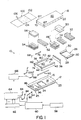
- Fig. 1 illustrates a mattress replacement apparatus 10 designed for use in any bed frame or other support surface.
- the mattress 10 includes a bottom cover or base 12 having a bottom surface 14 and a sidewall 16.
- Base 12 is illustratively made from an air impervious, wipeable and cleanable plastic material.
- Base includes a head end 23 and a foot end 25.
- Mattress 10 also includes a top air impermeable cover 18 having a top surface 20 and a downwardly extending sidewall 22. Top cover 18 is secured to base 12 with suitable fasteners such a zipper, snaps, or other coupling mechanism. An interior region 24 of mattress 10 is defined between the base 12 and the cover 18. A plurality of modular mattress components is located within the interior region 24 of mattress 10.
- Air support bladder 26 is located within interior region 24 of cover 12 adjacent head end 23.
- Air support bladder 26 includes a center inflatable portion 28 and a pair of spaced apart inflatable tubes 30.
- a head zone air cushion 32 and a shoulder zone air cushion 34 are located above surface 28 of air support 26.
- a lumbar cushion 36 is located within interior region 24 of base 12 adjacent shoulder zone cushion 34.
- a U-shaped air wall bladder 38 having side sections 40 and 42 and foot end section 44 is also located within interior region 24 of mattress 10 adjacent lumbar cushion 36.
- An air fluidized seat section or zone 48 is located within a center space 46 defined by air wall bladder 38.
- a seat section cover 50 is coupled over the air fluidized seat zone 48.
- a knee zone air cushion 52 is located within center space 46 adjacent air fluidized seat zone 48.
- An air fluidized foot zone 54 is located within center space 46 of air wall bladder 38 between knee zone cushion 52 and end wall 44.
- a foot zone cover 56 is coupled over the air fluidized foot zone 54.
- An air blower 58 is configured to blow air through a heat exchanger 60 and into a manifold 62.
- Manifold 62 is coupled to a plurality of control valves 64 which control air pressure supplied to various air zones within the mattress 10 in a conventional manner.
- Air from one of the control valves passes through tube 66 to connecter 68 which passes through an aperture 70 formed in top cover 18 into an aperture 74 formed in air wall bladder 38.
- Tube 76 is coupled to connector 68.
- Tube 76 extends through side portion 40 of air wall bladder 38.
- Tube 76 is coupled to an L-shaped connector 78 as shown in Fig. 8 to supply air to an inlet 80 of air fluidized seat zone 48 illustrated in Figs. 2 and 3.
- Connector 78 passes through aperture 82 formed in side section 40 of air wall bladder 38.
- Manifold connector 88 includes a plurality of output lines 90 to supply the various air zone bladders 26, 32, 34, 36, 38, and 52 with air through suitable connectors. Each zone includes snaps or other suitable fasteners to secure the zone to the cover 12 and adjacent zones.
- Another air inlet tube 92 is coupled to L-shaped connector 94 which extends through an aperture 96 formed in the bottom surface 14 of cover 12.
- the connector 94 is coupled to an air inlet 98 of air fluidized foot zone 54 as illustrated in Figs. 4 and 5.
- Fig. 1 illustrates an air quilt or blanket 100 designed to fit on top surface 20 of impermeable cover 18.
- the air blanket 100 is made of a disposable or washable material.
- the blanket 100 includes an impermeable layer 102 and an air permeable layer 104 which is supplied with air through a suitable connector 106.
- Layer 104 of air blanket 100 soaks up any drainage from a patient lying on the mattress 10 and also supplies air flow through layer 104. It is understood that the air flow layer 104 may extend across the entire air blanket 100, if desired.
- the air blanket 100 permits continuous air flow past the patient while maintaining the impermeable cover 18 to seal interior region 24 of mattress 10. Therefore, the mattress components and the air fluidizable medium within the air fluidized seat zone 48 and air fluidized foot zone 54 are not contaminated by fluids from the patient or other contaminants entering the mattress 10.
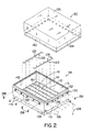
- a base 108 has a generally rectangular shape.
- a plurality of snaps 110 or other fasteners are provided to secure the air fluidized seat zone 48 to adjacent bladders.
- a frame 112 is configured to secure a diffuser sheet 114 to the base 108 as best shown in Fig. 3.
- the base 108 and frame 112 are preferably made from a urethane coated nylon twill and are impervious to air.
- Base 108 includes a bottom surface 109 and sidewall 111.
- Frame 112 is secured around its outer perimeter to an outer perimeter of base 108 by ultrasonic or RF welding and by sewing to provide both strength and sealing.
- a plurality of baffles 116 is coupled between the diffuser sheet 114 and bottom surface 109 of base 108.
- Baffles 116 are illustratively welded and sewn to bottom surface 109 and to webs 118 of frame 112 and to diffuser sheet 114.
- Baffles 116 maintain the plenum height and shape during operation.
- the baffles 116 include a plurality of apertures 120 to permit air flow through inlet 80 to pass through diffuser sheet 114 from the entire plenum 113 which is formed between base 108 and sheet 114.
- the diffuser sheet 114 is illustratively formed from a suitable woven fabric such as a twill weave which permits controlled air flow through the sheet 114. Sheet 114 provides sufficient air flow and pressure drop for movement of the fluidizable medium 115 as discussed below Illustratively, diffuser sheet 114 is a model number S-1500-SK11 woven material available from Tetko. Diffuser sheet 114 may also be formed from a microporous film made from, for example, polyurethane or other suitable material, which provides sufficient air flow and pressure drop for movement of the fluidizable medium 115.
- Metal strips 122 are coupled to opposite sidewalls 124 of frame 112 by suitable fasteners 126.
- the metal strips provide a ground connection for the air fluidized seat zone 48.
- one of the fasteners 126 on each side is coupled to a first end of a conductive cable 128 to provide a ground connection.
- An opposite end of each cable 128 is coupled to a controller outside the mattress 10.
- a sidewall 130 formed from an air impervious material is welded and sewn to the perimeter of frame 112
- the sidewall 130 includes a top zipper 132 configured to the coupled to a zipper 134 on cover 50.
- Sidewall 130 in Fig. 2 also includes anchor portions 136 and fastening clips 138 to hold down a flap 140 of top cover 50.
- At least a top surface 135 of cover 50 is formed from an air permeable material.
- the fluidizable medium 115 is loaded into the interior region by unzipping the cover 50 in the embodiment shown in Fig. 2.
- the sidewall 130 is formed to include an aperture 144 configured to receive a cap 146.
- the cover 50 is sewn and welded to the sidewall 130. The fluidizable medium is loaded and drained through the inlet aperture 144.
- the fluidizable medium 115 of the present invention includes both light weight beads and heavy weight beads to provide an overall reduced average weight for the beads. Reduced weight is important since the fluidized zones 48 and 54 are used in replacement mattress.
- Two types fluidizable medium 115 are illustratively mixed together and located within the interior region 142 of the fluidized seat section 48.
- the first size fluidizable medium 115 is illustratively conventional size tiny spheres or beads formed from glass, ceramics, or silicon having an average size between about 50 and about 150 microns, with a specific gravity of about 2.5.
- the lighter average weight of the fluidizable medium 115 of the present invention facilitates transfer of the mattress from one bed frame to another.
- the mattress 10 can be used on conventional bed frames.
- the modular components within the mattress 10 are replaceable sections. In other words, the air fluidized zones 48 and 54 may be replaced with standard air cushions if desired. If air fluidized sections such as 48 and 54 are required due to a particular therapy situation, then these modules or sections can be added to the mattress 10 as needed.
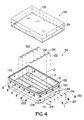
- Figs. 4 and 5 illustrate details of the air fluidized foot zone 54 of the present invention.
- Figs. 4 and 5 include structural components which function in the same or similar manner as components in the air fluidized seat zone 48 of Figs. 2 and 3. Those elements in Figs. 4 and 5 identified by reference numbers the same as in Figs. 2 and 3 perform the same or similar function.
- the dimensions of the rectangular fluidized zone 54 are different from the dimensions of seat zone 48 in Figs. 2 and 3.
- air is supplied into a lower plenum defined between base 108 and diffuser sheet 112 through an inlet 98 formed in bottom surface 109 of base 108.
- the cover 56 is coupled to the sidewall 130 by a zipper 132, 134.
- Fig. 4 illustrate details of the air fluidized foot zone 54 of the present invention.
- Figs. 4 and 5 include structural components which function in the same or similar manner as components in the air fluidized seat zone 48 of Figs. 2 and 3. Those elements in Figs. 4 and 5 identified
- top cover 56 is sewn and welded to sidewall 130.
- the fill inlet aperture 150 is formed in frame 112.
- a cap or closure 146 is provided to permit draining and filling of the fluidizable medium 115 into an interior region 142 of the foot zone 54.
- a notched portion 152 is formed inside wall 130 to accommodate the aperture 150.
- air is supplied to the lower plenum defined between base 108 and diffuser sheet 114 through either inlet 80 in Figs. 2 and 3 or inlet 98 in Figs. 4 and 5
- the baffles 116 maintained at plenum height and rectangular shape. Air diffuses through diffuser sheet 114 with sufficient air flow velocity and pressure drop to fluidize the fluidizable medium 115 located within interior region 142. Air can pass out through fluidized seat zone 48 and fluidized foot zone 54 through top covers 50 and 56, respectively.
- the top covers 50 and 56 are formed from a air permeable filter material (at least on top surface 135) which permits air flow through the cover 50 or 56 but does not permit the fluidizable medium 115 to escape through the covers 50 and 56.
- the fluidized seat zone 48 and foot zone 54 provide excellent support for a patient on the mattress 10 and reduce the likelihood of formation of bed sores because of equal distribution of pressure. Fluidized sections 48 and 54 are also well suited for treatment of patients with skin grafts because they do not produce high shear forces, which are frictional forces generated when the patient moves on the bed.
- the modular mattress operates at a cooler temperature than conventional fluidized beds.
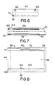
- Figs. 6-8 Additional details of the air wall bladder 38 are illustrated in Figs. 6-8. Because the impermeable cover 18 is coupled to the base 12, there is no way for air flowing through fluidized seat zone 48 and fluidized foot zone 54 to escape from mattress 10. Therefore, the side portions 40 and 42 of air wall bladder 38 are formed to include vent slots 160. Tubes 164 are located within side portions 40 and 42 aligned with slots 160. The tubes 164 are fabric tubes having holes to permit air flow into the tubes 164. The tubes 164 are illustratively RF welded around the boundary of slots 160. Tubes 164 include connectors 162 which extend through end wall 44 of air wall bladder 38. Connectors 162 are configured to be coupled to tubes 165 as illustrated in Fig. 1. Tubes 165 extend through apertures 167 in top cover 18.
- tubes 165 Opposite ends of tubes 165 are coupled to an exhaust fan 166 configured to withdraw air from the interior region of mattress 10 through vent slots 160, tubes 164, tubes 165, and fan 166. This provides an exhaust for air entering the mattress 10 through the fluidized seat zone 48 and fluidized foot zone 54. It is understood that other air fluidized zones may be included within the mattress 10 if desired.
- air impermeable cover 18 may be replaced with an upper low air loss section if desired.
- the upper low air loss section would permit air passing through the fluidized seat zone 48 and fluidized foot zone 54 to disburse through the low air loss cover without requiring an exhaust mechanism.
- FIG. 9 and 10 Another embodiment of the head section of the present invention is illustrated in Figs. 9 and 10.
- the replacement mattress is located on an articulating deck 170 of a bed.
- the deck includes a head section 172, a seat section 174, a thigh section 176, and a foot section 178.
- Figs. 9 and 10 show an alternative embodiment of the knee zone 52 which includes upper and lower chambers 180 and 182.
- the partitioned bladder sections 180 and 182 are maintained at different pressures.
- the mattress 10 of Figs. 9 and 10 includes a reduced shear head support section 184.
- a first array of air bladders 186 are coupled together by a web of material 188 coupled to the end of each air bladder 186.
- a web 188 is located at each end of the array of tubes 186.
- Tubes 186 are also tethered to bottom surface 14 of base 12 by tethers or by air bladders 190 which are coupled to base 14 and to air bladders 186.
- the web of material 188 and the array of bladders 186 are coupled to air wall bladder 38 by strap 192.
- Strap 192 includes a first end 194 coupled to air wall bladder 38 and a second end 196 coupled to web 188.
- Strap is coupled by suitable fasteners such as snaps.
- a strap 192 is located on both sides of mattress 10.
- a second array of bladders 198 are located on top of bladders 186. Bladders 198 are coupled to bladders 186.
- the bladder 186 adjacent lumbar cushion 36 engages the lumbar cushion 36 and causes the array of bladders 186 to pivot on tether bladders 190 relative to bottom surface 14 of base 12. This causes the array of bladders 186 to move in the direction of arrow 200 toward head end 23 of mattress 10.
- the top array of bladders 198 moves with the bottom array of bladders 186.
- the bladders 186 and 198 move about 4-5 inches (10.16-12.7 cm) toward the head end 23 of mattress 10 as the head section of mattress 10 is articulated. This causes reduced shear forces against a patient lying on the mattress.
- an anti-shear material can be positioned between the array of bladders 198 and the top cover 18 to facilitate sliding movement therebetween.
- the top array of bladders 198 may have any desired shape.
- the bladders may be generally rectangular as shown in Figs. 9 and 10, or the bladders 198 may be round such as the bladders 186.
- Fig. 11 illustrates another embodiment of the reduced shear head section of the present invention.
- the head section 202 includes an array of tubes 204 which are tethered to a central inflated section 206 by tethers 208. Opposite ends of tubes 204 are coupled together by a web 210 of material secured to tubes 204 by suitable technique such as RF welding. A pair of inflated side bolsters 212 is located on opposite sides of central inflated section 206. The array of tubes 204 is located adjacent lumbar cushion 36.
- the first bladder 204 engages lumbar section 36 and causes movement of the array of bladders 204 in the direction of arrow 216 to reduce shear forces on a body lying on the mattress 10.
- Figs. 12 and 13 illustrate another embodiment or the reduced shear head section which is similar to the embodiment illustrated in Fig. 11.
- a strap 192 is used to tie the head section 202 to the air wall bladder 38 as discussed above.
- First end 194 of strap 192 is coupled to the air wall bladder 38 by suitable connectors such as a snap or other suitable connector.
- the second end 196 of strap 192 is coupled to the array of bladders 204.
- the bladder 204 engages the air wall bladder 38 or a lumbar cushion, if installed, to cause the array of bladders 204 to pivot relative to bottom surface 14 of base 12. This causes bladders 204 to move in the direction of arrow 200 toward the head end 23 of mattress 10.
Claims (26)
- Matelas (10) comprenant une couverture externe (12, 18) formée d'un matériau imperméable à l'air, la couverture externe (12, 18) ayant une configuration qui délimite une région interne (24) et possédant.une surface supérieure de support (20), au moins un module de support (48, 54) par fluidisation d'air placé dans la région interne (24) de la couverture (12, 18) du matelas (10), le module (48, 54) à fluidisation d'air comprenant une chambre de pression (113), une chambre disposée au-dessus de la chambre de pression (113) et un matériau fluidisable (115) disposé dans la chambre, la chambre comprenant une surface supérieure (100) perméable à l'air, un raccord (80) couplé à la chambre de pression (113), le raccord ayant une configuration destinée à assurer le raccordement à une alimentation en air (58) destinée à transmettre de l'air à la chambre de pression (113) et à fluidiser le matériau fluidisable placé dans la chambre, caractérisé en ce qu'un raccord de ventilation (162) est raccordé à la couverture externe (12, 18) en communication avec la région interne (142) de la couverture (12, 18), le raccord de ventilation (162) ayant une configuration assurant l'évacuation d'air de la région interne (142) de la couverture (12, 18).
- Matelas selon la revendication 1, comprenant en outre un ventilateur (66) raccordé au raccord de ventilation (162) et destiné à faciliter l'extraction d'air de la région interne (142) de la couverture (12, 18).
- Matelas selon la revendication 1 ou 2, comprenant en outre un second raccord qui est raccordé à la couverture externe (12, 18), le second raccord ayant une configuration destinée à être raccordée à une alimentation en air (58), et un tube couplé entre le second raccord sur la couverture externe (12, 18) et le raccord de la chambre de pression (113) afin que de l'air soit transmis à la chambre de pression (113) par l'intermédiaire de la couverture externe (12, 18).
- Matelas selon la revendication 3, comprenant en outre un échangeur de chaleur (60) couplé entre l'alimentation en air (58) et le second raccord de la couverture externe (12, 18).
- Matelas selon l'une quelconque des revendications précédentes, dans lequel une vessie pneumatique (38) est placée près du module de support (48, 54) par fluidisation d'air et une conduite d'alimentation en air s'étend dans la vessie pneumatique (38), la conduite d'alimentation en air étant couplée au raccord pour transmettre de l'air à la chambre de pression (113).
- Matelas selon l'une quelconque des revendications 1 à 4, comprenant en outre une vessie pneumatique (38) placée afin qu'elle soit adjacente au module de support (48, 54) à fluidisation d'air dans la région interne (142) de la couverture (12, 18), la vessie pneumatique (38) étant formée afin qu'elle comprenne une fente de ventilation (160) communiquant avec le raccord de ventilation (162).
- Matelas selon la revendication 6, comprenant en outre un tube (164) ayant plusieurs trous couplés à la vessie pneumatique (38) en communication avec la fente de ventilation (160), le tube (164) étant couplé au raccord de ventilation (162).
- Matelas selon l'une quelconque des revendications précédentes, dans lequel plusieurs coussins pneumatiques (32, 34, 52) sont aussi disposés dans la région interne (142) de la couverture (12, 18).
- Matelas selon la revendication 8, dans lequel plusieurs coussins (32, 34, 52) sont des coussins de support imperméables à l'air.
- Matelas selon l'une quelconque des revendications précédentes, dans lequel un élément pneumatique rembourré (100) est placé à la surface supérieure (20) de la couverture (18).
- Matelas selon l'une quelconque des revendications précédentes, dans lequel le module (48, 54) de fluidisation comporte une base (108) formée d'un matériau imperméable à l'air, la base (108) ayant une surface inférieure (109) et une paroi latérale (111) dont la configuration délimite une région interne (142), un diffuseur (114) perméable à l'air placé dans la région interne (142) de la base (108), le diffuseur (114) étant couplé à la paroi latérale (111) de la base (108) pour délimiter la chambre et la chambre sous pression (113), et plusieurs déflecteurs (116) couplés à la base (108), les déflecteurs (116) étant disposés dans la chambre de pression (113).
- Matelas selon la revendication 11, comprenant en outre une couverture supérieure (54) qui comprend la surface supérieurs perméable à l'air (20) et une paroi latérale (22) qui s'étend depuis la surface supérieure (20), la paroi latérale (22) de la couverture supérieure (54) étant couplée a la paroi latérale (111) de la base (108).
- Matelas selon la revendication 11, dans lequel la paroi latérale (22) de la couverture supérieure (54) comprend une première moitié (134) de fermeture à glissière et la paroi latérale (111) de la base comprend une seconde moitié (132) de fermeture à glissière, la première moitié (134) et la seconde moitié (132) de fermeture à glissière étant couplées pour la fixation de la couverture supérieure (54) à la base (108).
- Matelas selon la revendication 12, dans lequel la couverture supérieure (54) peut être retirée de la base (108) pour donner accès au matériau fluidisable (115).
- Matelas selon l'une quelconque des revendications 11 à 14, comprenant en outre au moins une bande (122) de mise à la masse couplée à la paroi latérale (111) de la base (108).
- Matelas selon la revendication 15, dans lequel un câble conducteur (128) est couplé à la bande de mise à la masse au moins (122) pour assurer une connexion à la masse du module de support (48).
- Matelas selon l'une quelconque des revendications 11 à 16, dans lequel la base (108) comprend une surface inférieure (109), un châssis (112) et une paroi latérale séparée (124, 126) couplés mutuellement pour la formation de la base (108).
- Matelas selon l'une quelconque des revendications 11 à 16, dans lequel un châssis (112) est couplé à la paroi latérale (111) de la base (108), le châssis (112) ayant une configuration telle qu'il supporte le diffuseur (114).
- Matelas selon la revendication 18, dans lequel le châssis (112) comprend plusieurs joues (210) qui s'étendent entre les côtés opposés (124, 126) du châssis (112), les déflecteurs (116) étant couplés entre les joues (210) et la surface inférieure (109) de la base (108).
- Matelas selon la revendication 19, dans lequel les déflecteurs (116) sont soudés par ultrasons et cousus à la surface inférieure (109) aux joues (210) du châssis (112) et à la feuille de diffuseur (114).
- Matelas selon l'une quelconque des revendications 11 à 20, dans lequel les déflecteurs (116) sont formés chacun avec plusieurs orifices (120) destinés à permettre la circulation d'air dans la chambre de pression (113).
- Matelas selon l'une quelconque des revendications 11 à 21, dans lequel plusieurs organes de fixation (110) sont couplés à la paroi latérale (111) de la base (108), les organes de fixation (110) ayant une configuration assurant la fixation du module de support (48) dans le matelas (10).
- Matelas selon l'une quelconque des revendications précédentes, dans lequel la chambre comporte un canal d'accès (150) destiné à permettre l'extraction et l'insertion du matériau fluidisable (115).
- Matelas selon l'une quelconque des revendications précédentes, dans lequel le matelas comporte un tronçon (46) destiné à loger le module (48, 54) et un tronçon de support de tête (184) adjacent au tronçon de logement de module (46), le tronçon de support de tête (184) ayant une surface de support qui réduit les forces de cisaillement.
- Matelas selon la revendication 24, dans lequel le tronçon de support de tête (184) est couplé afin qu'il se déplace par rapport au tronçon de réception de module (46) par articulation d'une plate-forme (170) sur laquelle est placé le matelas (10).
- Matelas selon la revendication 24 ou 25, dans lequel le tronçon de réception de module (46) comporte aussi un module gonflable non fluidisé (52) raccordé à l'alimentation en air (58).
Priority Applications (2)
| Application Number | Priority Date | Filing Date | Title |
|---|---|---|---|
| EP02076243A EP1238606B1 (fr) | 1997-10-24 | 1998-10-23 | Matelas à zones fluidisées par de l'air |
| EP07075452A EP1820424A3 (fr) | 1997-10-24 | 1998-10-23 | Matelas à zones fluidisées par de l'air |
Applications Claiming Priority (3)
| Application Number | Priority Date | Filing Date | Title |
|---|---|---|---|
| US6311897P | 1997-10-24 | 1997-10-24 | |
| US63118P | 1997-10-24 | ||
| PCT/US1998/022526 WO1999021457A1 (fr) | 1997-10-24 | 1998-10-23 | Matelas a zones fluidisees par air |
Related Child Applications (1)
| Application Number | Title | Priority Date | Filing Date |
|---|---|---|---|
| EP02076243A Division EP1238606B1 (fr) | 1997-10-24 | 1998-10-23 | Matelas à zones fluidisées par de l'air |
Publications (2)
| Publication Number | Publication Date |
|---|---|
| EP1024733A1 EP1024733A1 (fr) | 2000-08-09 |
| EP1024733B1 true EP1024733B1 (fr) | 2003-01-15 |
Family
ID=22047044
Family Applications (3)
| Application Number | Title | Priority Date | Filing Date |
|---|---|---|---|
| EP07075452A Withdrawn EP1820424A3 (fr) | 1997-10-24 | 1998-10-23 | Matelas à zones fluidisées par de l'air |
| EP02076243A Expired - Lifetime EP1238606B1 (fr) | 1997-10-24 | 1998-10-23 | Matelas à zones fluidisées par de l'air |
| EP98953946A Expired - Lifetime EP1024733B1 (fr) | 1997-10-24 | 1998-10-23 | Matelas a zones fluidisees par air |
Family Applications Before (2)
| Application Number | Title | Priority Date | Filing Date |
|---|---|---|---|
| EP07075452A Withdrawn EP1820424A3 (fr) | 1997-10-24 | 1998-10-23 | Matelas à zones fluidisées par de l'air |
| EP02076243A Expired - Lifetime EP1238606B1 (fr) | 1997-10-24 | 1998-10-23 | Matelas à zones fluidisées par de l'air |
Country Status (11)
| Country | Link |
|---|---|
| US (4) | US6351862B1 (fr) |
| EP (3) | EP1820424A3 (fr) |
| JP (1) | JP2001520900A (fr) |
| KR (1) | KR20010031196A (fr) |
| CN (1) | CN1105538C (fr) |
| AT (2) | ATE230950T1 (fr) |
| AU (1) | AU1118799A (fr) |
| CA (1) | CA2308326A1 (fr) |
| CZ (1) | CZ20001429A3 (fr) |
| DE (2) | DE69837943T2 (fr) |
| WO (1) | WO1999021457A1 (fr) |
Families Citing this family (31)
| Publication number | Priority date | Publication date | Assignee | Title |
|---|---|---|---|---|
| DE69837943T2 (de) * | 1997-10-24 | 2007-12-20 | Hill-Rom Services, Inc., Batesville | Matratze mit Luftwirbelschichtkammern |
| EP1194106A1 (fr) * | 1999-07-06 | 2002-04-10 | Hill-Rom Services, Inc. | Ensemble matelas |
| US6689077B2 (en) | 1999-08-10 | 2004-02-10 | Reza R. Dabir | Apparatus and method for pressure management having temperature controlled air flow |
| JP4733897B2 (ja) * | 2000-02-25 | 2011-07-27 | ヒル−ロム サービシーズ,インコーポレイティド | ベッド用の空気流動袋 |
| GB0102655D0 (en) * | 2001-02-02 | 2001-03-21 | Worlds Apart Ltd | Sleeping apparatus |
| WO2003073825A2 (fr) * | 2002-02-28 | 2003-09-12 | Gaymar Industries, Inc. | Dispositif amortisseur autoreglable |
| EP1545345A1 (fr) * | 2002-08-08 | 2005-06-29 | Hill-Rom Services, Inc. | Matelas |
| WO2004043237A2 (fr) * | 2002-11-08 | 2004-05-27 | Barnes-Jewish Hospital | Dosages du decouplage de la synthese et de la degradation du collagene |
| US20050177951A1 (en) * | 2004-02-17 | 2005-08-18 | Zhu Guifang | Inflatable air mattress |
| JP2008505663A (ja) | 2004-04-30 | 2008-02-28 | タクテクス・コントロールズ・インコーポレイテッド | 自動圧力コントローラを有する身体支持装置、及び、身体支持方法 |
| US7469436B2 (en) * | 2004-04-30 | 2008-12-30 | Hill-Rom Services, Inc. | Pressure relief surface |
| US7543583B2 (en) * | 2004-07-28 | 2009-06-09 | Hill-Rom Services, Inc. | Forced air vent in siderail |
| US8470012B2 (en) | 2004-09-08 | 2013-06-25 | Arizant Healthcare Inc. | Inflatable convective pad for surgery |
| US7219380B2 (en) * | 2005-04-22 | 2007-05-22 | R&D Products, Llc | Multicompartmented air mattress |
| US9707141B2 (en) * | 2005-07-08 | 2017-07-18 | Hill-Rom Services, Inc. | Patient support |
| JP5231222B2 (ja) * | 2005-07-08 | 2013-07-10 | ヒル−ロム サービシーズ,インコーポレイティド | 患者支持体用制御ユニット |
| CA2666214A1 (fr) * | 2006-10-16 | 2008-04-24 | A.H. Beard Pty Ltd | Matelas pneumatique |
| WO2008131608A1 (fr) * | 2007-04-28 | 2008-11-06 | Enlanda | Matelas combine |
| US20090144903A1 (en) * | 2007-12-06 | 2009-06-11 | Delvaux Andrew B | Cpr facilitating mattress |
| US20110099722A1 (en) * | 2009-09-02 | 2011-05-05 | David Michael Moret | Mattresses with reinforcement inserts and densified stitch zones |
| CN101926714B (zh) * | 2010-07-23 | 2013-04-10 | 任晓宇 | 多功能预防褥疮护理床 |
| GB201017830D0 (en) * | 2010-10-21 | 2010-12-01 | Trinity College Dublin | Pneumatic mattress |
| US20130081205A1 (en) * | 2011-09-30 | 2013-04-04 | Michael M. Frondorf | Person support surface |
| GB201207839D0 (en) * | 2012-05-03 | 2012-06-20 | Psp Technology Ltd | Pneumatic mattress |
| US9060908B2 (en) | 2013-01-21 | 2015-06-23 | Hill-Rom Services, Inc. | Varying depth fluidized bed |
| US20140259427A1 (en) * | 2013-03-13 | 2014-09-18 | Hill-Rom Services, Inc. | Fabric diffuser for fluidized bed |
| US10238560B2 (en) | 2013-03-13 | 2019-03-26 | Hill-Rom Services, Inc. | Air fluidized therapy bed having pulmonary therapy |
| US9456701B2 (en) | 2014-06-13 | 2016-10-04 | Aeris Technology LLC | Valve assembly for controlling fluid communication between fluid chambers, inflatable device, and method |
| CN107854251A (zh) * | 2017-12-13 | 2018-03-30 | 泰兴市汇辰过滤器制造有限公司 | 一种船泊用于抢救的救生床 |
| US11389120B2 (en) | 2019-05-30 | 2022-07-19 | Hill-Rom Services, Inc. | Mattress having selectable patient weight valve, inductive power, and a digital x-ray cassette |
| WO2022061082A1 (fr) * | 2020-09-18 | 2022-03-24 | Hill-Rom Services, Inc. | Revêtement de matelas thérapeutique comprenant une gestion de rotation et d'humidité |
Family Cites Families (78)
| Publication number | Priority date | Publication date | Assignee | Title |
|---|---|---|---|---|
| US433905A (en) * | 1890-08-05 | Theodor muller | ||
| US2547840A (en) * | 1949-04-01 | 1951-04-03 | William B Smith | Sectional mattress |
| DE1606128U (de) * | 1950-01-09 | 1950-05-11 | Wetzell Gummiwerke A G | Luftmatratze. |
| FR2265347B1 (fr) * | 1974-03-27 | 1979-06-15 | Poudres & Explosifs Ste Nale | |
| US3978530A (en) * | 1975-11-21 | 1976-09-07 | Amarantos John G | Air inflatable bed-like device with adjustable back support |
| US4483029A (en) | 1981-08-10 | 1984-11-20 | Support Systems International, Inc. | Fluidized supporting apparatus |
| US4425676A (en) * | 1982-03-09 | 1984-01-17 | Crane Robert L | Cushion to reduce the incidence of decubitus ulcers in immobilized patients |
| FR2523841B1 (fr) | 1982-03-25 | 1985-10-25 | Lacoste Francois | Lit fluidise a usage therapeutique |
| US4644597A (en) * | 1983-05-09 | 1987-02-24 | Dynatech, Inc. | Air mattress with pressure relief valve |
| JPS60116351A (ja) * | 1983-11-30 | 1985-06-22 | 富士電機株式会社 | ビ−ズ流動式身体支持装置 |
| US4518203A (en) * | 1983-12-02 | 1985-05-21 | White Kirk E | Convertible cushion furniture |
| US4564965A (en) | 1984-01-17 | 1986-01-21 | Support Systems International, Inc. | Fluidized patient support system |
| US4879777A (en) | 1984-01-17 | 1989-11-14 | Support Systems International, Inc. | Fluidized patient support system |
| US4672699A (en) | 1984-01-17 | 1987-06-16 | Support Systems International, Inc. | Fluidized patient support system with side rail assembly |
| US4776050A (en) | 1984-01-17 | 1988-10-11 | Support Systems International, Inc. | Fluidized patient support system |
| US4609854A (en) * | 1985-02-01 | 1986-09-02 | Fuji Electric Company Ltd. | Control device for a hospital bed |
| US4637083A (en) | 1985-03-13 | 1987-01-20 | Support Systems International, Inc. | Fluidized patient support apparatus |
| US4638519A (en) | 1985-04-04 | 1987-01-27 | Air Plus, Inc. | Fluidized hospital bed |
| US4685163A (en) * | 1985-04-16 | 1987-08-11 | Quillen Jeffrey B | Recliner for medical convalescence |
| ATE81964T1 (de) * | 1985-05-10 | 1992-11-15 | Mediscus Prod Ltd | Patientenunterstuetzungsvorrichtung. |
| JPS61290953A (ja) * | 1985-06-19 | 1986-12-20 | 富士電機株式会社 | 身体支持具 |
| US4768250A (en) * | 1985-07-30 | 1988-09-06 | Fuji Electric Co., Ltd. | Fluidized bead bed |
| EP0263862B2 (fr) * | 1986-04-09 | 1996-04-10 | Constructions Industrielles De La Mediterranee- Cnim | Procede, dispositif et produit matelasse de maintien d'un objet |
| US4803744A (en) | 1987-05-19 | 1989-02-14 | Hill-Rom Company, Inc. | Inflatable bed |
| US5586348A (en) * | 1987-06-24 | 1996-12-24 | Ahlstrom Consumer Products Ltd. | Air mattress and method for adjusting it |
| NL8800792A (nl) * | 1988-03-29 | 1989-10-16 | Redactron Bv | Werkwijze en inrichting voor het onttrekken van vocht aan een of meer lichamen. |
| US4953247A (en) * | 1988-05-09 | 1990-09-04 | Hasty Charles E | Air-operated body support device |
| US5249318A (en) * | 1988-05-24 | 1993-10-05 | Loadsman Gerald H | Air support cushion |
| US5621934A (en) * | 1988-06-22 | 1997-04-22 | A. Ahlstrom Corporation | Mattress |
| US5008965A (en) | 1988-07-11 | 1991-04-23 | Kinetic Concepts, Inc. | Fluidized bead bed |
| US4998310A (en) * | 1988-10-12 | 1991-03-12 | Olson Robert V | Breakdown air mattress assembly |
| US4935635A (en) * | 1988-12-09 | 1990-06-19 | Harra Dale G O | System for measuring objects in three dimensions |
| US4914760A (en) | 1988-12-20 | 1990-04-10 | Ssi Medical Services, Inc. | Fluidized bed with collapsible side |
| US4942635A (en) * | 1988-12-20 | 1990-07-24 | Ssi Medical Services, Inc. | Dual mode patient support system |
| US4967431A (en) | 1988-12-20 | 1990-11-06 | SSI Medical Servies, Inc. | Fluidized bed with modular fluidizable portion |
| US5029352A (en) * | 1988-12-20 | 1991-07-09 | Ssi Medical Services, Inc. | Dual support surface patient support |
| US4951335A (en) * | 1989-06-05 | 1990-08-28 | Donan Marketing Corporation | Mattress assembly |
| US5020176A (en) * | 1989-10-20 | 1991-06-04 | Angel Echevarria Co., Inc. | Control system for fluid-filled beds |
| US5105487A (en) | 1990-12-17 | 1992-04-21 | Ssi Medical Services, Inc. | Apparatus for patient elevation above a fluidized surface |
| US5165141A (en) * | 1991-01-11 | 1992-11-24 | Ssi Medical Services, Inc. | Spring loaded heavy duty caster system for supporting a fluidized patient support system |
| FR2682293B1 (fr) * | 1991-10-11 | 1994-03-11 | Georges Roux | Lit medical fluidise muni d'un dispositif d'evacuation de ses constituants granulaires souilles. |
| CN2131385Y (zh) * | 1992-05-15 | 1993-05-05 | 杨建� | 防褥疮充气床垫 |
| US5325551A (en) * | 1992-06-16 | 1994-07-05 | Stryker Corporation | Mattress for retarding development of decubitus ulcers |
| US5267364A (en) * | 1992-08-11 | 1993-12-07 | Kinetic Concepts, Inc. | Therapeutic wave mattress |
| US5402542A (en) | 1993-04-22 | 1995-04-04 | Ssi Medical Services, Inc. | Fluidized patient support with improved temperature control |
| US5367728A (en) * | 1993-04-23 | 1994-11-29 | Chang; Ching-Lung | Adjustable ventilation mattress |
| US5345630A (en) * | 1993-07-15 | 1994-09-13 | Jack Healy | Quick inflatable air mattress |
| AT400222B (de) * | 1993-10-27 | 1995-11-27 | Schwarz Zoehrer Sabine | Liege für ein kleinkind |
| US5539943A (en) | 1994-03-08 | 1996-07-30 | Ssi Medical Services, Inc. | Apparatus and method for percussion of fluidized support surface |
| US5537701A (en) * | 1994-03-15 | 1996-07-23 | Maxwell Products, Inc. | Adjustable articulated bed |
| US5493742A (en) * | 1994-05-10 | 1996-02-27 | Lake Medical Products, Inc. | Ventilating air mattress with an inflating quilted pad |
| GB9410489D0 (en) | 1994-05-25 | 1994-07-13 | Egerton Hospital Equip | Improvements in and relating to low air-loss mattresses |
| US5623736A (en) | 1994-12-09 | 1997-04-29 | Suport Systems, International | Modular inflatable/air fluidized bed |
| US5560056A (en) * | 1995-01-27 | 1996-10-01 | Tai; Tsai-Ting | Multiple-purpose hammock, chair, and float type apparatus |
| CN2231061Y (zh) * | 1995-03-03 | 1996-07-17 | 张崇泰 | 空气床 |
| US6721979B1 (en) * | 1995-04-25 | 2004-04-20 | Kci Licensing, Inc. | Air bed with fluidized bead surface and related methods |
| JPH11504239A (ja) * | 1995-04-25 | 1999-04-20 | キネティック・コンセプツ・インコーポレーテッド | 流動化したビーズ面を有するエアベッド及び関連する方法 |
| TW270970B (en) * | 1995-04-26 | 1996-02-21 | Ehara Seisakusho Kk | Fluidized bed combustion device |
| US5682631A (en) * | 1995-08-04 | 1997-11-04 | Hill-Rom, Inc. | Bed having a reduced-shear pivot and step deck combination |
| US5991949A (en) * | 1995-08-15 | 1999-11-30 | Foamex L.P. | Hoseless air bed |
| US5655239A (en) * | 1996-09-20 | 1997-08-12 | Joerns Healthcare, Inc. | Cellular air loss mattress system |
| US5815865A (en) | 1995-11-30 | 1998-10-06 | Sleep Options, Inc. | Mattress structure |
| US5647079A (en) * | 1996-03-20 | 1997-07-15 | Hill-Rom, Inc. | Inflatable patient support surface system |
| US5699570A (en) * | 1996-06-14 | 1997-12-23 | Span-America Medical Systems, Inc. | Pressure relief valve vent line mattress system and method |
| US5873137A (en) * | 1996-06-17 | 1999-02-23 | Medogar Technologies | Pnuematic mattress systems |
| US5966763A (en) * | 1996-08-02 | 1999-10-19 | Hill-Rom, Inc. | Surface pad system for a surgical table |
| GB9618796D0 (en) * | 1996-09-09 | 1996-10-23 | Pegasus Airwave Ltd | Mattress cover |
| US5680662A (en) * | 1996-09-09 | 1997-10-28 | Veritas Enterprises, Inc. | Cushioning mattress for reducing shear and friction |
| US5781943A (en) * | 1997-03-13 | 1998-07-21 | Moenning; Stephen P. | Medical table and method for moving a patient from a first position to a second position |
| US5855207A (en) * | 1997-05-29 | 1999-01-05 | Moenning; Stephen P. | Medical table assembly having a restrainment apparatus mounted thereto and an associated method of immobilizing object |
| US6016581A (en) * | 1997-06-27 | 2000-01-25 | Miki; Sakae | Semi-fluid mattress |
| US6192537B1 (en) * | 1997-06-27 | 2001-02-27 | Sakae Miki | Semi-fluid based body support system |
| US5740573A (en) * | 1997-07-15 | 1998-04-21 | Boyd; Dennis | Air bed with circumferential belt |
| US6006379A (en) * | 1997-08-04 | 1999-12-28 | Patmark Company, Inc. | Articulating bed frame |
| DE69837943T2 (de) * | 1997-10-24 | 2007-12-20 | Hill-Rom Services, Inc., Batesville | Matratze mit Luftwirbelschichtkammern |
| US6073289A (en) * | 1997-12-18 | 2000-06-13 | Hill-Rom, Inc. | Air fluidized bed |
| US5966762A (en) * | 1998-07-01 | 1999-10-19 | Wu; Shan-Chieh | Air mattress for modulating ridden positions |
| JP4733897B2 (ja) * | 2000-02-25 | 2011-07-27 | ヒル−ロム サービシーズ,インコーポレイティド | ベッド用の空気流動袋 |
-
1998
- 1998-10-23 DE DE69837943T patent/DE69837943T2/de not_active Expired - Fee Related
- 1998-10-23 WO PCT/US1998/022526 patent/WO1999021457A1/fr not_active Application Discontinuation
- 1998-10-23 EP EP07075452A patent/EP1820424A3/fr not_active Withdrawn
- 1998-10-23 KR KR1020007004139A patent/KR20010031196A/ko not_active Application Discontinuation
- 1998-10-23 CN CN98810494A patent/CN1105538C/zh not_active Expired - Fee Related
- 1998-10-23 CA CA002308326A patent/CA2308326A1/fr not_active Abandoned
- 1998-10-23 AU AU11187/99A patent/AU1118799A/en not_active Abandoned
- 1998-10-23 CZ CZ20001429A patent/CZ20001429A3/cs unknown
- 1998-10-23 DE DE69810802T patent/DE69810802T2/de not_active Expired - Lifetime
- 1998-10-23 JP JP2000517629A patent/JP2001520900A/ja active Pending
- 1998-10-23 AT AT98953946T patent/ATE230950T1/de not_active IP Right Cessation
- 1998-10-23 AT AT02076243T patent/ATE364339T1/de not_active IP Right Cessation
- 1998-10-23 US US09/177,772 patent/US6351862B1/en not_active Expired - Fee Related
- 1998-10-23 EP EP02076243A patent/EP1238606B1/fr not_active Expired - Lifetime
- 1998-10-23 EP EP98953946A patent/EP1024733B1/fr not_active Expired - Lifetime
-
2002
- 2002-03-04 US US10/090,722 patent/US6564412B2/en not_active Expired - Lifetime
-
2003
- 2003-05-19 US US10/440,905 patent/US6735801B2/en not_active Expired - Fee Related
-
2004
- 2004-03-19 US US10/804,905 patent/US20040172764A1/en not_active Abandoned
Also Published As
| Publication number | Publication date |
|---|---|
| DE69837943D1 (de) | 2007-07-26 |
| US20020083529A1 (en) | 2002-07-04 |
| US6564412B2 (en) | 2003-05-20 |
| US20040172764A1 (en) | 2004-09-09 |
| US20030196271A1 (en) | 2003-10-23 |
| ATE364339T1 (de) | 2007-07-15 |
| DE69810802D1 (de) | 2003-02-20 |
| KR20010031196A (ko) | 2001-04-16 |
| EP1820424A2 (fr) | 2007-08-22 |
| AU1118799A (en) | 1999-05-17 |
| CA2308326A1 (fr) | 1999-05-06 |
| WO1999021457A1 (fr) | 1999-05-06 |
| EP1024733A1 (fr) | 2000-08-09 |
| CZ20001429A3 (cs) | 2001-11-14 |
| EP1238606A2 (fr) | 2002-09-11 |
| JP2001520900A (ja) | 2001-11-06 |
| CN1277544A (zh) | 2000-12-20 |
| EP1820424A3 (fr) | 2008-04-23 |
| ATE230950T1 (de) | 2003-02-15 |
| DE69837943T2 (de) | 2007-12-20 |
| CN1105538C (zh) | 2003-04-16 |
| EP1238606B1 (fr) | 2007-06-13 |
| US6735801B2 (en) | 2004-05-18 |
| US6351862B1 (en) | 2002-03-05 |
| EP1238606A3 (fr) | 2002-10-23 |
| DE69810802T2 (de) | 2003-11-06 |
Similar Documents
| Publication | Publication Date | Title |
|---|---|---|
| EP1024733B1 (fr) | Matelas a zones fluidisees par air | |
| EP0569058B1 (fr) | Système de support pour patient | |
| US5647079A (en) | Inflatable patient support surface system | |
| US5029352A (en) | Dual support surface patient support | |
| US5623736A (en) | Modular inflatable/air fluidized bed | |
| CA2355964C (fr) | Ensemble matelas | |
| US6694555B2 (en) | Air fluidized bladders for a bed | |
| US4914760A (en) | Fluidized bed with collapsible side | |
| US4967431A (en) | Fluidized bed with modular fluidizable portion | |
| US7155766B1 (en) | Bolster system and method | |
| US20090217460A1 (en) | Patient support | |
| CA2316461C (fr) | Couvre-pieds de lit fluidise | |
| EP2286783A2 (fr) | Lit fluidisé | |
| MXPA00003749A (en) | Mattress having air fluidized sections | |
| EP1139966B1 (fr) | Lit fluidise a base de billes, dote d'un diffuseur de billes gonflable | |
| EP0569056A2 (fr) | Système et metode de support pour patient | |
| EP0569057A2 (fr) | Système de support pour patient |
Legal Events
| Date | Code | Title | Description |
|---|---|---|---|
| PUAI | Public reference made under article 153(3) epc to a published international application that has entered the european phase |
Free format text: ORIGINAL CODE: 0009012 |
|
| 17P | Request for examination filed |
Effective date: 20000417 |
|
| AK | Designated contracting states |
Kind code of ref document: A1 Designated state(s): AT BE CH DE ES FR GB IE IT LI LU NL SE |
|
| RIN1 | Information on inventor provided before grant (corrected) |
Inventor name: ROMANO, JAMES, J. Inventor name: NOVACK, ROBERT, C. Inventor name: DELK, DANA, H. Inventor name: HENLEY, ALAN, W. |
|
| 17Q | First examination report despatched |
Effective date: 20001019 |
|
| GRAG | Despatch of communication of intention to grant |
Free format text: ORIGINAL CODE: EPIDOS AGRA |
|
| GRAG | Despatch of communication of intention to grant |
Free format text: ORIGINAL CODE: EPIDOS AGRA |
|
| GRAG | Despatch of communication of intention to grant |
Free format text: ORIGINAL CODE: EPIDOS AGRA |
|
| GRAH | Despatch of communication of intention to grant a patent |
Free format text: ORIGINAL CODE: EPIDOS IGRA |
|
| GRAH | Despatch of communication of intention to grant a patent |
Free format text: ORIGINAL CODE: EPIDOS IGRA |
|
| RAP1 | Party data changed (applicant data changed or rights of an application transferred) |
Owner name: HILL-ROM SERVICES, INC. |
|
| GRAA | (expected) grant |
Free format text: ORIGINAL CODE: 0009210 |
|
| AK | Designated contracting states |
Kind code of ref document: B1 Designated state(s): AT BE CH DE ES FR GB IE IT LI LU NL SE |
|
| PG25 | Lapsed in a contracting state [announced via postgrant information from national office to epo] |
Ref country code: NL Free format text: LAPSE BECAUSE OF FAILURE TO SUBMIT A TRANSLATION OF THE DESCRIPTION OR TO PAY THE FEE WITHIN THE PRESCRIBED TIME-LIMIT Effective date: 20030115 Ref country code: LI Free format text: LAPSE BECAUSE OF FAILURE TO SUBMIT A TRANSLATION OF THE DESCRIPTION OR TO PAY THE FEE WITHIN THE PRESCRIBED TIME-LIMIT Effective date: 20030115 Ref country code: CH Free format text: LAPSE BECAUSE OF FAILURE TO SUBMIT A TRANSLATION OF THE DESCRIPTION OR TO PAY THE FEE WITHIN THE PRESCRIBED TIME-LIMIT Effective date: 20030115 Ref country code: BE Free format text: LAPSE BECAUSE OF FAILURE TO SUBMIT A TRANSLATION OF THE DESCRIPTION OR TO PAY THE FEE WITHIN THE PRESCRIBED TIME-LIMIT Effective date: 20030115 Ref country code: AT Free format text: LAPSE BECAUSE OF FAILURE TO SUBMIT A TRANSLATION OF THE DESCRIPTION OR TO PAY THE FEE WITHIN THE PRESCRIBED TIME-LIMIT Effective date: 20030115 |
|
| REG | Reference to a national code |
Ref country code: GB Ref legal event code: FG4D Ref country code: CH Ref legal event code: EP |
|
| REG | Reference to a national code |
Ref country code: IE Ref legal event code: FG4D |
|
| REF | Corresponds to: |
Ref document number: 69810802 Country of ref document: DE Date of ref document: 20030220 Kind code of ref document: P |
|
| PG25 | Lapsed in a contracting state [announced via postgrant information from national office to epo] |
Ref country code: SE Free format text: LAPSE BECAUSE OF FAILURE TO SUBMIT A TRANSLATION OF THE DESCRIPTION OR TO PAY THE FEE WITHIN THE PRESCRIBED TIME-LIMIT Effective date: 20030415 |
|
| NLV1 | Nl: lapsed or annulled due to failure to fulfill the requirements of art. 29p and 29m of the patents act | ||
| PG25 | Lapsed in a contracting state [announced via postgrant information from national office to epo] |
Ref country code: ES Free format text: LAPSE BECAUSE OF FAILURE TO SUBMIT A TRANSLATION OF THE DESCRIPTION OR TO PAY THE FEE WITHIN THE PRESCRIBED TIME-LIMIT Effective date: 20030730 |
|
| REG | Reference to a national code |
Ref country code: CH Ref legal event code: PL |
|
| ET | Fr: translation filed | ||
| PG25 | Lapsed in a contracting state [announced via postgrant information from national office to epo] |
Ref country code: LU Free format text: LAPSE BECAUSE OF NON-PAYMENT OF DUE FEES Effective date: 20031023 Ref country code: IE Free format text: LAPSE BECAUSE OF NON-PAYMENT OF DUE FEES Effective date: 20031023 |
|
| PLBE | No opposition filed within time limit |
Free format text: ORIGINAL CODE: 0009261 |
|
| STAA | Information on the status of an ep patent application or granted ep patent |
Free format text: STATUS: NO OPPOSITION FILED WITHIN TIME LIMIT |
|
| 26N | No opposition filed |
Effective date: 20031016 |
|
| REG | Reference to a national code |
Ref country code: IE Ref legal event code: MM4A |
|
| PGFP | Annual fee paid to national office [announced via postgrant information from national office to epo] |
Ref country code: IT Payment date: 20071029 Year of fee payment: 10 |
|
| PG25 | Lapsed in a contracting state [announced via postgrant information from national office to epo] |
Ref country code: IT Free format text: LAPSE BECAUSE OF NON-PAYMENT OF DUE FEES Effective date: 20081023 |
|
| PGFP | Annual fee paid to national office [announced via postgrant information from national office to epo] |
Ref country code: FR Payment date: 20101020 Year of fee payment: 13 |
|
| PGFP | Annual fee paid to national office [announced via postgrant information from national office to epo] |
Ref country code: DE Payment date: 20101020 Year of fee payment: 13 |
|
| PGFP | Annual fee paid to national office [announced via postgrant information from national office to epo] |
Ref country code: GB Payment date: 20101020 Year of fee payment: 13 |
|
| GBPC | Gb: european patent ceased through non-payment of renewal fee |
Effective date: 20111023 |
|
| REG | Reference to a national code |
Ref country code: FR Ref legal event code: ST Effective date: 20120629 |
|
| PG25 | Lapsed in a contracting state [announced via postgrant information from national office to epo] |
Ref country code: DE Free format text: LAPSE BECAUSE OF NON-PAYMENT OF DUE FEES Effective date: 20120501 |
|
| REG | Reference to a national code |
Ref country code: DE Ref legal event code: R119 Ref document number: 69810802 Country of ref document: DE Effective date: 20120501 |
|
| PG25 | Lapsed in a contracting state [announced via postgrant information from national office to epo] |
Ref country code: FR Free format text: LAPSE BECAUSE OF NON-PAYMENT OF DUE FEES Effective date: 20111102 Ref country code: GB Free format text: LAPSE BECAUSE OF NON-PAYMENT OF DUE FEES Effective date: 20111023 |