EP1024583A2 - Rotor complètement encapsulé - Google Patents
Rotor complètement encapsulé Download PDFInfo
- Publication number
- EP1024583A2 EP1024583A2 EP00101799A EP00101799A EP1024583A2 EP 1024583 A2 EP1024583 A2 EP 1024583A2 EP 00101799 A EP00101799 A EP 00101799A EP 00101799 A EP00101799 A EP 00101799A EP 1024583 A2 EP1024583 A2 EP 1024583A2
- Authority
- EP
- European Patent Office
- Prior art keywords
- sleeve
- electrical machine
- rotor assembly
- machine according
- magnetic fields
- Prior art date
- Legal status (The legal status is an assumption and is not a legal conclusion. Google has not performed a legal analysis and makes no representation as to the accuracy of the status listed.)
- Withdrawn
Links
- 229910052751 metal Inorganic materials 0.000 claims abstract description 13
- 239000002184 metal Substances 0.000 claims abstract description 13
- 238000000034 method Methods 0.000 claims abstract description 12
- 238000007789 sealing Methods 0.000 claims description 6
- 238000005538 encapsulation Methods 0.000 claims description 3
- 230000006698 induction Effects 0.000 claims description 3
- RYGMFSIKBFXOCR-UHFFFAOYSA-N Copper Chemical compound [Cu] RYGMFSIKBFXOCR-UHFFFAOYSA-N 0.000 claims description 2
- 229910052782 aluminium Inorganic materials 0.000 claims description 2
- XAGFODPZIPBFFR-UHFFFAOYSA-N aluminium Chemical compound [Al] XAGFODPZIPBFFR-UHFFFAOYSA-N 0.000 claims description 2
- 239000011324 bead Substances 0.000 claims description 2
- 229910052802 copper Inorganic materials 0.000 claims description 2
- 239000010949 copper Substances 0.000 claims description 2
- 229910001092 metal group alloy Inorganic materials 0.000 claims description 2
- 230000005415 magnetization Effects 0.000 description 4
- 238000004519 manufacturing process Methods 0.000 description 3
- 239000000463 material Substances 0.000 description 3
- BGPVFRJUHWVFKM-UHFFFAOYSA-N N1=C2C=CC=CC2=[N+]([O-])C1(CC1)CCC21N=C1C=CC=CC1=[N+]2[O-] Chemical compound N1=C2C=CC=CC2=[N+]([O-])C1(CC1)CCC21N=C1C=CC=CC1=[N+]2[O-] BGPVFRJUHWVFKM-UHFFFAOYSA-N 0.000 description 2
- QJVKUMXDEUEQLH-UHFFFAOYSA-N [B].[Fe].[Nd] Chemical compound [B].[Fe].[Nd] QJVKUMXDEUEQLH-UHFFFAOYSA-N 0.000 description 1
- 238000004026 adhesive bonding Methods 0.000 description 1
- 239000000969 carrier Substances 0.000 description 1
- 239000011248 coating agent Substances 0.000 description 1
- 238000000576 coating method Methods 0.000 description 1
- 230000006735 deficit Effects 0.000 description 1
- 239000007788 liquid Substances 0.000 description 1
- 229910001172 neodymium magnet Inorganic materials 0.000 description 1
- 230000035515 penetration Effects 0.000 description 1
- 238000003825 pressing Methods 0.000 description 1
- 238000005476 soldering Methods 0.000 description 1
- 239000010935 stainless steel Substances 0.000 description 1
- 229910001220 stainless steel Inorganic materials 0.000 description 1
- 238000003466 welding Methods 0.000 description 1
Images

Classifications
-
- H—ELECTRICITY
- H02—GENERATION; CONVERSION OR DISTRIBUTION OF ELECTRIC POWER
- H02K—DYNAMO-ELECTRIC MACHINES
- H02K1/00—Details of the magnetic circuit
- H02K1/06—Details of the magnetic circuit characterised by the shape, form or construction
- H02K1/22—Rotating parts of the magnetic circuit
- H02K1/27—Rotor cores with permanent magnets
- H02K1/2706—Inner rotors
- H02K1/272—Inner rotors the magnetisation axis of the magnets being perpendicular to the rotor axis
- H02K1/274—Inner rotors the magnetisation axis of the magnets being perpendicular to the rotor axis the rotor consisting of two or more circumferentially positioned magnets
- H02K1/2753—Inner rotors the magnetisation axis of the magnets being perpendicular to the rotor axis the rotor consisting of two or more circumferentially positioned magnets the rotor consisting of magnets or groups of magnets arranged with alternating polarity
- H02K1/278—Surface mounted magnets; Inset magnets
-
- H—ELECTRICITY
- H02—GENERATION; CONVERSION OR DISTRIBUTION OF ELECTRIC POWER
- H02K—DYNAMO-ELECTRIC MACHINES
- H02K15/00—Processes or apparatus specially adapted for manufacturing, assembling, maintaining or repairing of dynamo-electric machines
- H02K15/02—Processes or apparatus specially adapted for manufacturing, assembling, maintaining or repairing of dynamo-electric machines of stator or rotor bodies
- H02K15/03—Processes or apparatus specially adapted for manufacturing, assembling, maintaining or repairing of dynamo-electric machines of stator or rotor bodies having permanent magnets
-
- H—ELECTRICITY
- H02—GENERATION; CONVERSION OR DISTRIBUTION OF ELECTRIC POWER
- H02K—DYNAMO-ELECTRIC MACHINES
- H02K5/00—Casings; Enclosures; Supports
- H02K5/04—Casings or enclosures characterised by the shape, form or construction thereof
- H02K5/12—Casings or enclosures characterised by the shape, form or construction thereof specially adapted for operating in liquid or gas
- H02K5/128—Casings or enclosures characterised by the shape, form or construction thereof specially adapted for operating in liquid or gas using air-gap sleeves or air-gap discs
Definitions
- the invention relates to a method for liquid-tight Encapsulation of the rotor package of an electrical machine, in particular an electric motor for operating a Canned tube pump, the surrounding and the shaft Rotor package carrying permanent magnets from a sleeve Sheet metal is surrounded for sealing.
- the invention relates at the same time an electrical machine with a shaft load-bearing and permanent magnet rotor package, wherein the rotor package for sealing a sleeve made of sheet metal is surrounded.
- the object of the invention is to provide a method with which the rotor of an electrical machine beneath Ensuring high tightness in a simple way can be encapsulated inexpensively.
- Object of the invention an electrical machine with a easy to manufacture and tightly encapsulated rotor create.
- the magnetic fields are advantageously generated by a pulsed current generated in a pulse tool Circumferential direction is guided around the sleeve. It is in the Sleeve also in the circumferential direction but especially in opposite current induced, so that a resulting force arises in the radial direction.
- the current pulses advantageously have a pulse duration of about 0.1 ms and a strength of 500 kA.
- the corresponding Magnetic fields generated by induction have a field strength up to 200,000 A / cm.
- a possible impairment to compensate for the magnetization of the permanent magnets it is advantageous to use the permanent magnets either only after the Encapsulate or magnetize through magnetization Apply a magnetic field in the radial direction freshen up.
- the sleeve is generally used for receiving centrifugal forces, to solidify the package and to Sealing against the medium.
- the magnet is carried Carrier body made of metal, the magnetic yoke guaranteed to be pressed onto the shaft. After the magnets are inserted into the gaps between the segments Plastic holder used to keep the segments from slipping to prevent. Depending on the end faces of the support body one with a central hole for the shaft Cover plate, in particular made of sheet metal or plastic, is put on. After shrinking the sleeve, grasp it the ends of which are the outer edges of both cover plates. A such cover plate is advantageously with an O-ring sealed against the shaft and against the magnetic carrier.
- the rotor pack has one cylindrical magnetic carrier that closes around the magnetic circuit true is equipped with a support body and one for the inclusion of the magnets provided and as a support cage trained plastic holder.
- the support cage closes in the axial direction with two lids from plastic, the diameter of which is the diameter of the rotor package.
- On the magnetic carrier now shrunk the sleeve.
- the shrunk sleeve overlaps the lid of the plastic holder.
- the cover plates are advantageously in the outer circumference provided with a groove or a bead into which the material the sleeve can flow. Through this facility is one ensures particularly reliable sealing.
- the sleeve is made of an easily deformable metal, especially copper, Aluminum or a light metal alloy. This Materials are particularly suitable for the deformation by magnetic forces.
- the wall thickness of the sleeve is less than 1 mm.
- the inside diameter of the sleeve is advantageously dimensioned so that it is approximately 0.5 mm larger than that Outside diameter of the rotor package.
- the sleeve on the one hand can easily be pushed onto the rotor package, while on the other hand, by the magnetic forces deformation caused is sufficient to securely close the gap close. Furthermore, the support body and Magnetic segments existing package a coarser tolerance have, whereby the usual grinding of the Rotor outer diameter can be omitted.
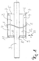
- FIG. 1 represents the state of a Rotor package with a pushed sleeve 1 before the magnetic deformation was made.
- the rotor package includes one equipped with permanent magnets 4 Magnetic carrier 2, which is enclosed by the sleeve 1.
- the lower half of Figure 1 shows the state before the upper Half after deformation.
- the figure shows on its left side an embodiment of a magnet holder 2 and on the right side another embodiment.
- the magnet carrier 2 is on the shaft put on and by means of a press fit or a fit held with starring.
- the magnetic carrier 2 made of plastic has recesses in which the permanent magnets 4 in appropriate recesses.
- On the with The magnet 1 provided with the permanent magnet 4 is the sleeve 1 slipped out of thin sheet metal in a play fit (lower Half of the picture).
- the right half of the picture shows a magnetic carrier 2, which has a flat end wall 5 in the axial direction (Cover) closes.
- the end wall 5 is on the outer edge 6 provided with a phase and towers over the inserted one Permanent magnets 4 in the radial direction.
- the cover 9 is with a O-ring 10 against the shaft 3 and against the end face of the Carrier body 12 sealed. After magnetic deformation grips the end 11 of the sleeve 1 the outer chamfered edge the cover plate 9.
- FIG. 2 shows a pulse tool 13 in the form of a metallic Cylinder with an axial notch 18, the sleeve 1 too whose application encompasses magnetic fields.
- a Power source 14, which is used to generate the pulse tool 13 required current is shown schematically. With the power source 14 is in the tool in the circumferential direction running current 15 generated in the sleeve 1 in opposite direction current 16 induced. Both currents 15 and 16 generate axial magnetic fields, which compresses between the sleeve 1 and the tool 13 are radially directed and homogeneous on the sleeve 1 generate distributed forces (arrows 17). These radial forces 17 shrink the sleeve 1 onto the rotor assembly and flare the Edge 7 of the sleeve 1 around the end walls 5.
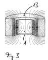
- Figure 3 shows the course of the magnetic fields are compressed between the sleeve 1 and the tool 13.
- the course of the oppositely directed currents is through the symbols ⁇ and ⁇ are shown.
Landscapes
- Engineering & Computer Science (AREA)
- Power Engineering (AREA)
- Manufacturing & Machinery (AREA)
- Permanent Field Magnets Of Synchronous Machinery (AREA)
- Structures Of Non-Positive Displacement Pumps (AREA)
Applications Claiming Priority (2)
| Application Number | Priority Date | Filing Date | Title |
|---|---|---|---|
| DE19903251A DE19903251A1 (de) | 1999-01-28 | 1999-01-28 | Vollverkapselter Rotor |
| DE19903251 | 1999-01-28 |
Publications (2)
| Publication Number | Publication Date |
|---|---|
| EP1024583A2 true EP1024583A2 (fr) | 2000-08-02 |
| EP1024583A3 EP1024583A3 (fr) | 2002-04-03 |
Family
ID=7895584
Family Applications (1)
| Application Number | Title | Priority Date | Filing Date |
|---|---|---|---|
| EP00101799A Withdrawn EP1024583A3 (fr) | 1999-01-28 | 2000-01-28 | Rotor complètement encapsulé |
Country Status (2)
| Country | Link |
|---|---|
| EP (1) | EP1024583A3 (fr) |
| DE (1) | DE19903251A1 (fr) |
Cited By (6)
| Publication number | Priority date | Publication date | Assignee | Title |
|---|---|---|---|---|
| EP1533883A1 (fr) * | 2003-11-18 | 2005-05-25 | SISME IMMOBILIARE S.p.A. | Rotor à aimant permanent à assemblage rapide pour moteurs électriques et procédé de fabrication d'un tel rotor |
| EP1843449A1 (fr) * | 2006-04-07 | 2007-10-10 | General Electric Company | Motoeur d'un compresseur comprenant un rotor aux aimants permanents pour le transport d'un fluide dans une pipeline |
| DE102010005963A1 (de) * | 2010-01-28 | 2011-08-18 | Minebea Co., Ltd. | Rotor mit umspritzter Hülse |
| EP2151040A4 (fr) * | 2007-05-09 | 2015-11-04 | Carter Fuel Systems Llc | Ensemble de moteur bldc |
| PL239130B1 (pl) * | 2020-03-13 | 2021-11-08 | Siec Badawcza Lukasiewicz Instytut Napedow I Masz Elektrycznych Komel | Wirnik silnika z magnesami trwałymi |
| WO2025170827A1 (fr) * | 2024-02-05 | 2025-08-14 | Borgwarner Inc. | Rotor pour machine électrique et machine électrique comprenant le rotor |
Families Citing this family (5)
| Publication number | Priority date | Publication date | Assignee | Title |
|---|---|---|---|---|
| DE10058267A1 (de) * | 2000-11-23 | 2002-05-29 | Wilo Gmbh | Axiale Lagerung des Rotors einer elektrischen Maschine |
| DE10060121A1 (de) | 2000-12-04 | 2002-06-06 | Alstom Switzerland Ltd | Verfahren zur Herstellung eines Permanentmagnete enthaltenden Rotors einer Synchronmaschine und nach diesem Verfahren hergestellter Rotor |
| DE102004034176A1 (de) * | 2004-07-15 | 2006-02-16 | Minebea Co., Ltd. | Rotoranordnung für eine elektrische Maschine |
| JP4671997B2 (ja) * | 2007-10-23 | 2011-04-20 | 三菱電機株式会社 | 回転電機の回転子、及びその製造方法 |
| DE202009013649U1 (de) | 2009-10-28 | 2009-12-24 | Messner Gmbh & Co Kg | Bürstenloser Rotor für elektrische Spaltrohrpumpe |
Family Cites Families (5)
| Publication number | Priority date | Publication date | Assignee | Title |
|---|---|---|---|---|
| DE2138357B2 (de) * | 1971-07-31 | 1973-08-09 | Licentia Patent-Verwaltungs-Gmbh, 6000 Frankfurt | Verfahren zur bearbeitung der sitzflaechen eines leichtmetallgussgehaeuses fuer elektrische maschinen |
| SE412823B (sv) * | 1978-12-12 | 1980-03-17 | Flygt Ab | Sett att montera en komplett stator i ett omgivande hus |
| US4404483A (en) * | 1981-02-26 | 1983-09-13 | Taco, Inc. | Method of fabricating a wet-rotor circulator and circulator produced thereby |
| US4414523A (en) * | 1981-09-04 | 1983-11-08 | Micropump Corporation | Encapsulated magnet for magnetic drive |
| DE19602951C2 (de) * | 1996-01-27 | 2000-12-07 | Steingroever Magnet Physik | Verfahren und Vorrichtung zum Aufweiten von Rohren oder rohrförmigen Teilen durch das Magnetfeld eines Strom-Impulses |
-
1999
- 1999-01-28 DE DE19903251A patent/DE19903251A1/de not_active Withdrawn
-
2000
- 2000-01-28 EP EP00101799A patent/EP1024583A3/fr not_active Withdrawn
Non-Patent Citations (1)
| Title |
|---|
| None |
Cited By (8)
| Publication number | Priority date | Publication date | Assignee | Title |
|---|---|---|---|---|
| EP1533883A1 (fr) * | 2003-11-18 | 2005-05-25 | SISME IMMOBILIARE S.p.A. | Rotor à aimant permanent à assemblage rapide pour moteurs électriques et procédé de fabrication d'un tel rotor |
| EP1843449A1 (fr) * | 2006-04-07 | 2007-10-10 | General Electric Company | Motoeur d'un compresseur comprenant un rotor aux aimants permanents pour le transport d'un fluide dans une pipeline |
| US7709988B2 (en) | 2006-04-07 | 2010-05-04 | General Electric Company | Methods and apparatus for using an electrical machine to transport fluids through a pipeline |
| CN101051770B (zh) * | 2006-04-07 | 2013-10-23 | 通用电气公司 | 利用电机通过管道输送流体的方法和设备 |
| EP2151040A4 (fr) * | 2007-05-09 | 2015-11-04 | Carter Fuel Systems Llc | Ensemble de moteur bldc |
| DE102010005963A1 (de) * | 2010-01-28 | 2011-08-18 | Minebea Co., Ltd. | Rotor mit umspritzter Hülse |
| PL239130B1 (pl) * | 2020-03-13 | 2021-11-08 | Siec Badawcza Lukasiewicz Instytut Napedow I Masz Elektrycznych Komel | Wirnik silnika z magnesami trwałymi |
| WO2025170827A1 (fr) * | 2024-02-05 | 2025-08-14 | Borgwarner Inc. | Rotor pour machine électrique et machine électrique comprenant le rotor |
Also Published As
| Publication number | Publication date |
|---|---|
| EP1024583A3 (fr) | 2002-04-03 |
| DE19903251A1 (de) | 2000-08-03 |
Similar Documents
| Publication | Publication Date | Title |
|---|---|---|
| DE2433770C2 (de) | Verfahren zum Herstellen eines Stators für eine elektrische Maschine | |
| EP3913771B1 (fr) | Moteur électrique | |
| DE112010003859B4 (de) | Drehmotor vom Lundell-Typ | |
| EP1850014B1 (fr) | Pompe centrifuge | |
| EP0899857B1 (fr) | Dispositif rotatif avec palier magnétique | |
| DE19757605C2 (de) | Elektromotor mit Kühlung | |
| EP1024583A2 (fr) | Rotor complètement encapsulé | |
| EP3289669B1 (fr) | Machine électrique sans boîtier | |
| DE3440193A1 (de) | Laeufer mit permanent-magneten | |
| DE102004017157A1 (de) | Verfahren zur Herstellung einer Rotoranordnung und Rotoranordnung für eine elektrische Maschine | |
| DE4331803A1 (de) | Elektronisch kommutierter Elektromotor | |
| DE112013000316T5 (de) | Drehende Elektromaschine mit Hybriderregung | |
| EP2930825A1 (fr) | Montage d'aimants permanents sur un rotor d'une machine électrique | |
| DE102011101730A1 (de) | Elektromotor | |
| DE102021132222A1 (de) | Statorgehäuse für eine Axialflussmaschine | |
| DE102007028356A1 (de) | Permanent erregter Rotor für Arbeitsmaschinen | |
| DE10349442A1 (de) | Elektrische Maschine mit Permanentmagnetrotor und Verfahren zu dessen Herstellung | |
| US6958555B2 (en) | Method for producing an encased rotor of a permanent magnet | |
| EP1104078B1 (fr) | Machine électrique avec un rotor muni de tôles frontales emmanchées à force | |
| AT511025B1 (de) | Dynamoelektrische Maschine und Handstück für dental- oder medizinische Behandlung | |
| EP0713282A1 (fr) | Moteur à manchin d'entrefer | |
| EP1516408B1 (fr) | Moteur electrique, notamment moteur sans balais, a rotor excite par aimant permanent et procede permettant de le produire | |
| DE102013221795A1 (de) | Rotor mit Sicherungsringen für eine Asynchronmaschine sowie Verfahren zum Fertigen derselben | |
| DE10100717C1 (de) | Permanentmagnet-Rotor für eine elektrische Maschine | |
| EP4038722B1 (fr) | Rotor à excitation permanente à géométrie d'aimant améliorée |
Legal Events
| Date | Code | Title | Description |
|---|---|---|---|
| PUAI | Public reference made under article 153(3) epc to a published international application that has entered the european phase |
Free format text: ORIGINAL CODE: 0009012 |
|
| AK | Designated contracting states |
Kind code of ref document: A2 Designated state(s): AT BE CH CY DE DK ES FI FR GB GR IE IT LI LU MC NL PT SE |
|
| AX | Request for extension of the european patent |
Free format text: AL;LT;LV;MK;RO;SI |
|
| PUAL | Search report despatched |
Free format text: ORIGINAL CODE: 0009013 |
|
| AK | Designated contracting states |
Kind code of ref document: A3 Designated state(s): AT BE CH CY DE DK ES FI FR GB GR IE IT LI LU MC NL PT SE |
|
| AX | Request for extension of the european patent |
Free format text: AL;LT;LV;MK;RO;SI |
|
| RIC1 | Information provided on ipc code assigned before grant |
Free format text: 7H 02K 15/03 A, 7H 02K 1/27 B, 7H 02K 5/12 B |
|
| STAA | Information on the status of an ep patent application or granted ep patent |
Free format text: STATUS: THE APPLICATION HAS BEEN WITHDRAWN |
|
| 18W | Application withdrawn |
Withdrawal date: 20020924 |