EP1024485A2 - Kassettentransportgerät - Google Patents
Kassettentransportgerät Download PDFInfo
- Publication number
- EP1024485A2 EP1024485A2 EP00101582A EP00101582A EP1024485A2 EP 1024485 A2 EP1024485 A2 EP 1024485A2 EP 00101582 A EP00101582 A EP 00101582A EP 00101582 A EP00101582 A EP 00101582A EP 1024485 A2 EP1024485 A2 EP 1024485A2
- Authority
- EP
- European Patent Office
- Prior art keywords
- cartridge
- shutter
- driving roller
- opening
- holder
- Prior art date
- Legal status (The legal status is an assumption and is not a legal conclusion. Google has not performed a legal analysis and makes no representation as to the accuracy of the status listed.)
- Withdrawn
Links
Images


Classifications
-
- G—PHYSICS
- G11—INFORMATION STORAGE
- G11B—INFORMATION STORAGE BASED ON RELATIVE MOVEMENT BETWEEN RECORD CARRIER AND TRANSDUCER
- G11B17/00—Guiding record carriers not specifically of filamentary or web form, or of supports therefor
- G11B17/02—Details
- G11B17/04—Feeding or guiding single record carrier to or from transducer unit
- G11B17/041—Feeding or guiding single record carrier to or from transducer unit specially adapted for discs contained within cartridges
- G11B17/043—Direct insertion, i.e. without external loading means
- G11B17/0436—Direct insertion, i.e. without external loading means with opening mechanism of the cartridge shutter
Definitions
- the present invention relates to a reproducing apparatus and a recording/reproducing apparatus using a cartridge such as MD (minidisk) or MO (magneto-optic disk), particularly to a cartridge transporting apparatus for transporting a cartridge between a prescribed input/output position and a recording/reproducing position.
- a cartridge such as MD (minidisk) or MO (magneto-optic disk)
- Previously known is a cartridge having a structure in which a recording/reproducing medium such as a MD, MO, etc. is housed in a cartridge case.
- a conventional reproducing apparatus using such a cartridge is disclosed in JP-A-8-315481.
- a cartridge transporting mechanism automatically starts a loading operation so that the cartridge being held in a cartridge holder is horizontally transported to a prescribed position in a reproducing apparatus. Thereafter, the cartridge and cartridge holder which are held integrated are dropped into a prescribed reproducing position so that the cartridge is clamped there.
- the cartridge transporting mechanism attached to the conventional reproducing apparatus the cartridge is horizontally transported to the above prescribed position by rotating a roller by a driving motor while it is in contact with the side wall or edge of the cartridge inserted from the insertion opening.
- the present invention has been accomplished in order to obviate such an inconvenience.
- An object of the present invention is to provide a cartridge transporting apparatus which can transport a cartridge to a prescribed reproducing position surely and accurately.
- a cartridge transporting apparatus comprising: a cartridge holder for loading a cartridge with a recording medium which is inserted from an inlet; a reproducing means including a turn table and a pick-up, said cartridge holder and said reproducing means being moved relatively so that the cartridge loaded in the cartridge holder can be reproduced; a driving roller, provided in the vicinity of said insertion opening, for transporting said cartridge in its contact with a lower face or upper surface of the cartridge into said cartridge holder, a shutter opening/closing means engaged with a shutter covering an opening of said cartridge, for opening/closing said shutter as said cartridge is moved, wherein said driving roller is located at a position where it is not brought in contact with the shutter when said shutter is engaged with said shutter opening/closing means.
- a cartridge transporting apparatus comprising: a cartridge holder for loading a cartridge with a recording medium which is inserted from an inlet; a reproducing means including a turn table and a pick-up, said cartridge holder and said reproducing means being moved relatively so that the cartridge loaded in the cartridge holder can be reproduced; a driving roller, provided in the vicinity of said insertion opening, for transporting said cartridge in its contact with a lower face or upper surface of the cartridge into said cartridge holder, a shutter opening/closing means engaged with a shutter covering an opening of said cartridge, for opening/closing said shutter as said cartridge is moved, wherein said driving roller is located at a position where it is brought in contact with the shutter after said shutter passes said driving roller.
- the driving roller rotates in contact with the lower or upper surface of the cartridge to carry the cartridge into a cartridge holder. This provides sufficient contact between the driving roller and the cartridge so that the shutter can be opened or closed surely, and the cartridge can be loaded to a recording/reproducing position reliably and accurately.
- the driving roller is adapted so that it does not affect the opening/closing of a shutter, it is possible to prevent an accident that the recording/reproducing medium in a cartridge is damaged as a result that the shutter is opened while the cartridge is transported.
- a cartridge transporting apparatus which is applied to a recording/reproducing apparatus using an MD cartridge (hereinafter referred to as "cartridge”) .
- the explanation will be made assuming that the direction of carrying in the cartridge is an x direction, that of clamping the cartridge is a z direction and that orthogonal to the x direction and z direction is a y direction.
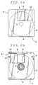
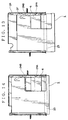
- Fig. 2A is a plan view of the cartridge when viewed from the surface side.
- Fig. 2B is a plan view of the cartridge when viewed from the back side.
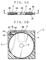
- Fig. 3A is a side view in a direction of A of Fig. 2B.
- Fig. 3B is a sectional view taken in line B - B in Fig. 3A.
- the cartridge has a structure based on a prescribed standard in which a disk-shaped recording/reproducing medium 4 supported by a circular clamping region 3 is housed in a cartridge case 2 with resin-molded square shells superposed on each other.
- the cartridge case 2 includes, on its back side, a square opening 5 from which the one side of the recording/reproducing medium 4 during recording/reproducing is exposed, a shutter 6 for protecting the recording/reproducing medium 4 by covering the opening 5 during the other period than the reproducing, a circular supporting hole 7 for rotatably supporting the clamping region 3 and positioning holes 8 and 9 for positioning the cartridge 1 at a prescribed reproducing position in a reproducing apparatus.
- the shutter 6 slides within an concave area 2C formed on the front surface of the cartridge case 2 and formed on the back surface thereof to open/close an opening 5.
- a stopper for 6A for stopping the open of the shutter 6 is provided to protrude in a direction of carrying in the cartridge 2.
- an engagement hole 6B is provided which is to be engaged with an engagement spring 24A attached to a cartridge holder 24 (described later).
- guide grooves 2A and 2B are formed for guiding the movement of the shutter 6.
- the above stopper 6A is movably guided by the guide groove 2B.
- the cartridge 2 is provided with a stopper portion 2F having an engagement concave portion 2E in its interior.
- the engagement concave portion 2E is to be engaged with the stopper 6A for the shutter 6 is provided.
- the engagement portion 2F which is made of an elastic material, is pivoted on a rotary shaft 2G. When a slanted plane 2H is pressed, the engagement concave portion 2E is depressed so that it is disengaged from the stopper 6A.
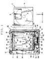
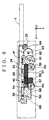
- Fig. 1 is a plan view of the cartridge transporting 10 which is applied to a recording/reproducing apparatus using an cartridge 1.
- fixing members 12 -15 having oscillation-proofing structure for fixing the cartridge transporting apparatus are attached at four positions of the bottom of a square hard frame 11.
- the first and the second side plate 16 and 17 are arranged in parallel in the x-direction.
- a through-hole 19 is made for exposing a pick-up for read information and its moving mechanism, and a turn table (not shown) upward in a z-direction.
- the turn table serves to mount the clamping region 3 of the cartridge 1 for reproducing and to rotate it.
- These pick-up and turn table constitute a reproducing means.
- the rotary center position of the turn table is indicated by reference numeral 20.
- Projections 21 and 22 are uprighted apart by a prescribed interval therebetween upward from the bottom of the hard frame 11 so that they are adapted to be engaged with the holes for positioning the cartridge.
- a driving roller 23 is provided which is perpendicular to the first and the second side plate 16 and 17.
- the driving roller 23 having the same length as the width (i. e. length in the y-direction) of the cartridge 1 is formed in a shape of circular cylinder with a metallic rotary shaft which is covered with hard rubber having a friction resistance on its circumferencial face.
- the driving roller 23 are rotatably supported at both ends of the rotary shaft. The contact area between the driving roller 23 and the cartridge can be assured sufficiently to reduce anxiety of slip.
- the driving roller 23 is arranged on the second side plate 17.
- the driving roller, which serves to transport the cartridge 1, is arranged at a position which does not influence the opening/closing of the shutter 6.
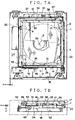
- a square cartridge holder 24 is arranged above the hard frame 11 between the first and the second side plate 16 and 17.
- a steering member 24 is arranged between the outer walls of the cartridge 24 and the inner walls of the first and the second side plate 16 and 17.
- a through-hole 27 is made for exposing the turn table in such a manner that it overlaps the through-hole 27 for exposing the turn table.
- the cartridge holder 24 On both sides of the bottom wall 26 in the y-direction, as seen from the side view of Fig. 4B, the cartridge holder 24 has side walls 28 and 29 each having a prescribed height and visors 30 and 31 attached to upper ends the side walls 28 and 29 inwardly.
- the side walls 28, 29 and visors 30, 31 are integrally molded to the bottom wall 26 by the technique such as bending.
- the cartridge holder 24 has engagement projections 32 and 33 oriented outwardly in the y-direction at the prescribed positions of the side walls 28 and 29.
- the side wall 28 is provided with an engagement spring 24A to be engaged with the engagement hole 6B of the shutter 6 and an engagement releasing piece 24B which slides within the guide groove 2B of the cartridge case 2 and also slides the slanted face 2H of the stopper portion 2F to be depressed.
- the shutter 6 can be opened/closed in accordance with the carry-in/out operation of the cartridge 1.
- the cartridge 1 is adapted to be inserted horizontally from a carry-in/out position on the side of the driving roller 23 into a square gap 24a defined by the bottom wall 26, side walls 28, 29 and visors 30, 31.
- the cartridge 1 is adapted to be inserted in such a fashion that its bottom face (rear face) is oriented toward the driving roller 23.
- the steering member 25 includes a first arm 34 which intervenes between the first side plate 16 and the side wall 28 of the cartridge holder 24, a second arm which intervenes between the second side plate 17 and the side wall of the cartridge holder 24, and a coupling member 36 coupling these first and second arms 34 and 35 with each other.
- the first and the second arm 34 and 35 have a plurality of engagement projections 37, 38, 39, 40 and 41 which protrude inwardly in the y-direction at the prescribed positions of the arms 34 and 35.
- the second arm 35 of the steering member 25 has a pair of guiding projections 43 and 44 which protrude from the bottom thereof.
- the second arm 35 has a slanted guiding hole 42 slanted on the skew for the x-direction and y-direction.
- the second side plate 17 has lengthy engagement holes 45, 46 and 47 in the x-direction and an inverted-L shaped guide hole 48.
- the supporting member 18 has guide members 49 and 50 for guiding the steering member 25 back and forth in the x-direction while they are engaged with the guiding protrusions 43 and 44.
- the engagement projections 39, 40 and 41 of the second arm 35 are fit in the engagement holes 45, 46 and 47.
- the engagement projection 33 of the cartridge holder 24 as shown from the side view of the Fig. 5A is fit in the hole formed when the slanted guide hole 42 of the second arm 35 and the inverted L-shaped guide hole 48 of the second side plate 17 overlap.
- the cartridge 24 and the second arm 35 of the steering member 25 are combined with the second side plate 17.
- the inverted-L shaped guide hole 48 is composed of a first lengthy hole component 48a and a second lengthy hole component 48b, which are integrated to each other.
- the first lengthy hole component 48a has a length which permits the engagement projection 33 to be movable within a prescribed distance in an x-direction.
- the second lengthy hole component 48b has a length which permits the engagement projection 33 to be movable up and down within a prescribed distance in a z-direction.
- the slanted guide hole 42 is slanted over the length of the second lengthy hole component 48b of the inverted-L shaped guide hole 48.
- the length of the first lengthy hole component 48a in the x-direction is made approximately equal to a moving distance over which the cartridge holder 24 is moved to a reproducing position in loading (described later).
- the length of the second lengthy hole component 48c in the z-direction is made approximately equal to a clamping distance over which the cartridge holder 24 is clamped to the reproducing position.
- the slanted guide hole 42 is designed with respect to its slanting angle and length so that the engagement projection is movable in the first and the second lengthy guide hole 48a and 48b.
- the engagement projection 33 is fit in the above slanted guide hole 42 and inverted-L shaped guide hole 48. Therefore, when the engagement projection 33 resides in the first lengthy hole component 48a, if the steering member 25 moves in the x-direction, the engagement projection 33 moves in the x-direction under control by the first lengthy hole component 48a. On the other hand, when the engagement projection 33 resides in the second lengthy hole component 48b, if the steering member 25 moves in the x-direction, the engagement projection 33 moves up and down in the z-direction according to the overlapping position of the second lengthy hole component 48b and the slanted guide hole 42.
- engagement holes 45, 46 and 47 are made for supporting engagement protrusions 39, 40, 41, respectively. Therefore, the engagement holes 45, 46 and 47 are designed to have a length permitting the steering member 25 to be movable within a range in the x-direction of the first lengthy hole component 48a.
- the first arm 34 of the steering member 25 also has a slanted guide hole similar to the slanted guide hole 42 of the second arm 35.
- the first side plate 16 also has engagement holes and an inverted-L shaped guide hole similar to the engagement holes 45 - 47 and the inverted-L shaped guide hole 48 of the second side plate 17.
- the cartridge holder 24 and first arm 34 of the steering member 25 are combined with the first side plate 16 in such a manner that the engagement projections 32, 37 and 38 are fit in the slanted guide hole, engagement hole and inverted-L shaped guide hole on the side of the first side plate 16 and first arm 34. Therefore, when the steering member 25 moves in the x-direction, the cartridge holder 24 can move with no slant nor rattle.
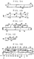
- a rack member 51 as shown in Fig. 5D is arranged on the outside of the second side plate 17.
- the rack member 51 has elliptical eccentric holes 52, 53, gear 54 and a contact hole 55 which extends to the inside of the cartridge holder 24.
- the rack member 51 is arranged on the outside of the second side plate 17 in such a manner that the engagement projections 39 and 40 are fit in the eccentric holes 52 and 53 as shown in Fig. 5E.
- the length of each of the eccentric holes 52 and 53 of the rack member 51 is designed to be equal to the maximum apart distance between a gear 69 and a gear portion 54 which will be described later.
- FIG. 6 is a side view of the holder transporting mechanism seen from the side of the second side plate.
- the holder transporting mechanism is supported by a supporting member 18 and is provided with a driving motor 56 and plural worm gears 57, 58 and gears 59 - 69.
- the gear 59 is engaged with the worm gear 57 coupled with the driving shaft of the driving motor 56.
- the gear 61 is engaged with the small-diameter gear 60 integrated with the gear 59.
- the gear 63 is engaged with the small-diameter gear 62 integrated with the gear 61.
- the gear 64 fixed to the rotary shaft of the driving roller 23 is engaged with the gear 63.
- the gear 65 is engaged with the worm gear 57.
- the gear 66 is engaged with the worm gear 58 integrated with the gear 65.
- the gear 68 is engaged with the small-diameter gear 67 integrated with the gear 66.
- the small-diameter gear 69 integrated with the gear 68 is located at a position where the small-diameter gear 69 is apart by the maximum apart distance from the gear portion 54 when the rack 51 moves rightmost under control by the eccentric holes 52 and 53.
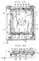
- FIGs. 7A, 8A, 9A and 10A are plan views of the cartridge transporting apparatus 10 when seen from above, while Figs. 7B, 8B, 9B and 10B are side views of the cartridge transporting apparatus when seen from the side of the rack 51 in which the holder transporting mechanism except the gear 69 is not shown.
- the operation will be explained typically of the cartridge holder 24, steering member 25 and rack member 51 for the second side plate 17. The operation will be not explained about the cartridge holder 24, steering member 25 and rack member 25 and rack member for the first side plate 16.
- the rack member 51 moves rightward according to the displacement between the engagement protrusions 39, 40 and the elliptical eccentric holes 52, 53.
- the engagement protrusions 33, 39, 40 and 41 as shown in Figs. 5A - 5C are limited by the engagement holes 45, 46 and 47, slanted guide hole 42 and inverted-L shaped guide hole 48.
- the cartridge holder 24 and steering meter 25 are at rest at a rightmost position for the first side plate 17.
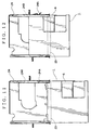
- Figs. 11 - 15 are views for explaining the operation of the shutter 6.
- Fig. 11 shows the state when the cartridge has been connected to the rear of the driving roller 23 so that carrying of the cartridge 1 into the cartridge holder 24 toward the inner part thereof has been started.
- the shutter 6 is still closed.
- the stopper 6A of the shutter 6 is engaged with the engagement concave portion 2E of the stopper portion 2F of the cartridge case 2 so that the shutter 6 is secured.
- the tip of the shutter 6 is brought into contact with the engagement spring 24A of the cartridge holder 24.
- the engagement spring 24A is pulled up as the cartridge 1 is moved, and slides along the side of the shutter 6.
- the driving roller 23 is brought into contact with the shutter 6 so that the shutter 6 remains at the closed position. Therefore, the shutter 6 does not slide owing to the rotary force of the driving roller 23.
- the shutter 6 secured at the closed position goes beyond the driving roller 23. Thereafter, the engagement releasing piece 24B is brought into contact with the slanted surface 2H of the stopper portion 2F so that the slanted plane 2H is pressed down as the cartridge is moved. As a result, the stopper 6A of the shutter 6 is disengaged from the engagement concave portion 2E of the stopper portion 2F. Further, when the cartridge 1 is further moved, the tip of the engagement releasing piece 24B of the cartridge holder 24 is brought into contact with the side end of the shutter 6 and the engagement spring 24A of the cartridge holder 24 is engaged with the engagement hole 6B of the shutter 6.
- the driving roller 23 is located at a position free from the operation of opening the shutter. Specifically, the driving roller 23 is located at the position past the contact with the shutter 6 when the opening operation of the shutter is started so that the driving roller 23 does not hinder the opening operation of the shutter 6.
- the shutter 6 is moved together with the cartridge 1 so that the shutter 6 is completely opened.
- the cartridge holder 24 is moved horizontally until the engagement projection 33 reaches the leftmost position of the inverted-L guide hole 48.
- the cartridge 1 inserted in the cartridge holder 24 is carried into the position immediately above the turn table.
- the rack 51 is pulled leftward by the gear 69 and the steering member 25 is successively leftward in the figure.
- the engagement protrusion 33 is moved in a direction defined by the slanted hole 42 and inverted-L shape guide hole 48, i.e. z-direction.
- the cartridge holder 24 is forcibly descended toward the bottom wall of the hard plate 11.
- the clamping region 3 of the cartridge 1 is loaded on the turn table so that it is aligned with the rotary center position 20.
- the cartridge 1 is loaded surely and accurately in a prescribed recording/reproducing position since the positioning protrusions 21 and 22 uprighted from the hard frame 11 are fit in the positioning holes 8 and 9.
- the contact area between the cartridge 1 and driving roller 23 is increased, thereby improving the reliability of transportation. Further, the increase in the contact area between the cartridge 1 and driving roller 23 greatly reduces the aberration of the contact face of the driving roller 23. Since the cartridge 1 can be transported with the driving roller 23 not being in contact with the sliding shutter 6, an accident that the sliding shutter 6 is inadvertently opened during transportation to injure the recording/reproducing medium 4 can be prevented.
- the cartridge can be transported to a prescribed recording/reproducing position surely and accurately.
- the driving roller 23 carries in/out the cartridge 1 while it is kept in contact with the shutter 6.
- the driving roller 23, which is shortened, may be located on the second side plate so that the driving roller is not in contact with the shutter 6.
- the driving roller 23 carries in/out the cartridge 1 which it is kept in contact with the lower surface of the cartridge 1.
- the driving roller 23 may carry in/out the cartridge 1 while it is in contact with the upper surface of the cartridge 1.
- the single driving roller 23 was provided in order to carry in/out the cartridge 1.
- Another driving roller which is opposite to the driving roller may be provided for this purpose.
- the cartridge 1 can be carried in/out while it is sandwiched between both driving rollers.
- the inverted L-shaped guide hole 48 and slanted guide hole 42 should not be limited to the shapes as shown in Figs. 5C and 5B, respectively. Specifically, where the cartridge holder 24 is to be clamped upward in the z-direction, the guide hole 48 is formed in an L-shape instead of the inverted L-shape, and the slanted guide hole 42 is formed in a shape ascending from left toward right instead of the shape descending from left toward right.
- the cartridge holder 24 was moved the x-direction and z-direction.
- the cartridge holder 24 may be moved in only the x-direction, and instead of the movement in the z-direction of the cartridge holder 24, a reproducing means (not shown) may be risen in the z-direction.
- the present invention was applied to the reproducing means.
- the present invention can be applied to a recording/reproducing device equipped with a magnetic head for recording information.
Landscapes
- Feeding And Guiding Record Carriers (AREA)
Applications Claiming Priority (2)
| Application Number | Priority Date | Filing Date | Title |
|---|---|---|---|
| JP2197699 | 1999-01-29 | ||
| JP11021976A JP2000222804A (ja) | 1999-01-29 | 1999-01-29 | カートリッジ搬送装置 |
Publications (2)
| Publication Number | Publication Date |
|---|---|
| EP1024485A2 true EP1024485A2 (de) | 2000-08-02 |
| EP1024485A3 EP1024485A3 (de) | 2000-12-06 |
Family
ID=12070071
Family Applications (1)
| Application Number | Title | Priority Date | Filing Date |
|---|---|---|---|
| EP00101582A Withdrawn EP1024485A3 (de) | 1999-01-29 | 2000-01-27 | Kassettentransportgerät |
Country Status (2)
| Country | Link |
|---|---|
| EP (1) | EP1024485A3 (de) |
| JP (1) | JP2000222804A (de) |
Family Cites Families (5)
| Publication number | Priority date | Publication date | Assignee | Title |
|---|---|---|---|---|
| DE3672000D1 (de) * | 1985-08-10 | 1990-07-19 | Sanyo Electric Co | Frontladevorrichtung fuer plattengeraet. |
| JP3127186B2 (ja) * | 1993-10-12 | 2001-01-22 | クラリオン株式会社 | カートリッジローディング機構 |
| JPH07226000A (ja) * | 1994-02-15 | 1995-08-22 | Matsushita Electric Ind Co Ltd | カートリッジローディング装置 |
| JP3424227B2 (ja) * | 1997-06-04 | 2003-07-07 | 日本ビクター株式会社 | ミニディスク及びコンパクトディスクの兼用ディスクプレーヤ |
| JPH11328809A (ja) * | 1998-05-13 | 1999-11-30 | Sony Corp | 光ディスク装置のローディング装置 |
-
1999
- 1999-01-29 JP JP11021976A patent/JP2000222804A/ja active Pending
-
2000
- 2000-01-27 EP EP00101582A patent/EP1024485A3/de not_active Withdrawn
Also Published As
| Publication number | Publication date |
|---|---|
| EP1024485A3 (de) | 2000-12-06 |
| JP2000222804A (ja) | 2000-08-11 |
Similar Documents
| Publication | Publication Date | Title |
|---|---|---|
| US4881141A (en) | Driving apparatus for a magnetic head | |
| US5300763A (en) | Information recording/reproducing apparatus | |
| US4873598A (en) | Mechanism for supporting and guiding a head carriage | |
| JP3021442B2 (ja) | ディスクプレ―ヤ― | |
| EP0539199A2 (de) | Plattenkassetteladegerät | |
| US6268977B1 (en) | Disk cartridge loading apparatus and disk storage apparatus including such disk cartridge loading apparatus | |
| US5784351A (en) | Loading apparatus for disk cartridge | |
| US5303102A (en) | Disk drive apparatus having head guard | |
| EP1024485A2 (de) | Kassettentransportgerät | |
| US5602695A (en) | Cassette loading mechanism for recording and playback apparatus | |
| US5331611A (en) | Transmission mechanism for magnetic-field generating device in photo-magnetic type recording/reproducing apparatus | |
| US6388973B1 (en) | Cartridge transporting apparatus | |
| US5343447A (en) | Self-cooling optomagnetic disk device with locking internal mechanism | |
| US7162726B2 (en) | Disk apparatus | |
| US4853806A (en) | Apparatus for regulating the force rendered to a magnetic disc by a magnetic head in a rotary magnetic disc device | |
| JPH0258755A (ja) | カセット装着装置 | |
| US6252747B1 (en) | Disk apparatus having an improved head carriage structure | |
| US20010033443A1 (en) | Large capacity disk drive | |
| JP3214539B2 (ja) | 磁気記録再生装置のヘッド移送機構 | |
| JPH035015Y2 (de) | ||
| JPH0345318Y2 (de) | ||
| JP3210576B2 (ja) | 磁気ヘッド保持機構 | |
| JP2000100039A (ja) | カートリッジ搬送装置 | |
| JPH0323554A (ja) | 電子カメラ | |
| JPH06295556A (ja) | テープカセット |
Legal Events
| Date | Code | Title | Description |
|---|---|---|---|
| PUAI | Public reference made under article 153(3) epc to a published international application that has entered the european phase |
Free format text: ORIGINAL CODE: 0009012 |
|
| AK | Designated contracting states |
Kind code of ref document: A2 Designated state(s): DE FR GB |
|
| AX | Request for extension of the european patent |
Free format text: AL;LT;LV;MK;RO;SI |
|
| PUAL | Search report despatched |
Free format text: ORIGINAL CODE: 0009013 |
|
| AK | Designated contracting states |
Kind code of ref document: A3 Designated state(s): AT BE CH CY DE DK ES FI FR GB GR IE IT LI LU MC NL PT SE |
|
| AX | Request for extension of the european patent |
Free format text: AL;LT;LV;MK;RO;SI |
|
| RIC1 | Information provided on ipc code assigned before grant |
Free format text: 7G 11B 17/04 A, 7G 11B 23/04 B, 7G 11B 33/08 B |
|
| 17P | Request for examination filed |
Effective date: 20001117 |
|
| AKX | Designation fees paid |
Free format text: DE FR GB |
|
| 17Q | First examination report despatched |
Effective date: 20041021 |
|
| STAA | Information on the status of an ep patent application or granted ep patent |
Free format text: STATUS: THE APPLICATION IS DEEMED TO BE WITHDRAWN |
|
| 18D | Application deemed to be withdrawn |
Effective date: 20050503 |