EP1024371A2 - Gerät zur Bilderzeugung mittels magnetischer Kernresonanz - Google Patents
Gerät zur Bilderzeugung mittels magnetischer Kernresonanz Download PDFInfo
- Publication number
- EP1024371A2 EP1024371A2 EP99309547A EP99309547A EP1024371A2 EP 1024371 A2 EP1024371 A2 EP 1024371A2 EP 99309547 A EP99309547 A EP 99309547A EP 99309547 A EP99309547 A EP 99309547A EP 1024371 A2 EP1024371 A2 EP 1024371A2
- Authority
- EP
- European Patent Office
- Prior art keywords
- magnetic resonance
- resonance imaging
- imaging apparatus
- data samples
- motion
- Prior art date
- Legal status (The legal status is an assumption and is not a legal conclusion. Google has not performed a legal analysis and makes no representation as to the accuracy of the status listed.)
- Granted
Links
Images

Classifications
-
- G—PHYSICS
- G01—MEASURING; TESTING
- G01R—MEASURING ELECTRIC VARIABLES; MEASURING MAGNETIC VARIABLES
- G01R33/00—Arrangements or instruments for measuring magnetic variables
- G01R33/20—Arrangements or instruments for measuring magnetic variables involving magnetic resonance
- G01R33/44—Arrangements or instruments for measuring magnetic variables involving magnetic resonance using nuclear magnetic resonance [NMR]
- G01R33/48—NMR imaging systems
- G01R33/54—Signal processing systems, e.g. using pulse sequences ; Generation or control of pulse sequences; Operator console
- G01R33/56—Image enhancement or correction, e.g. subtraction or averaging techniques, e.g. improvement of signal-to-noise ratio and resolution
- G01R33/563—Image enhancement or correction, e.g. subtraction or averaging techniques, e.g. improvement of signal-to-noise ratio and resolution of moving material, e.g. flow contrast angiography
- G01R33/56375—Intentional motion of the sample during MR, e.g. moving table imaging
-
- G—PHYSICS
- G01—MEASURING; TESTING
- G01R—MEASURING ELECTRIC VARIABLES; MEASURING MAGNETIC VARIABLES
- G01R33/00—Arrangements or instruments for measuring magnetic variables
- G01R33/20—Arrangements or instruments for measuring magnetic variables involving magnetic resonance
- G01R33/28—Details of apparatus provided for in groups G01R33/44 - G01R33/64
Definitions
- This invention relates to magnetic resonance (MR) imaging apparatus.
- the subject to be imaged is positioned in a strong magnetic field, for example, produced in the bore of a superconducting electromagnet, and the protons of hydrogen atoms (and of other MR active nuclei) in water and fat align parallel and anti-parallel to the main magnetic field, precessing around the direction of the field at the Larmor frequency.
- a strong magnetic field for example, produced in the bore of a superconducting electromagnet
- a transmit coil applies pulses of r.f. energy at the Larmor frequency in a direction orthogonal to the main field to excite precessing nuclei to resonance, which results in the net magnetisation of all MR active nuclei being flipped from the direction of the main magnetic field into a direction having a transverse component in which it can be detected by the use of a receive coil.
- the received signal can be spatially encoded to produce two-dimensional (slice) or three-dimensional (slab) information about the distribution of MR active nuclei and hence of water and tissue.
- the received signal can be confined to a slice of the patient in the following way.
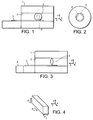
- a superconducting electromagnet 1 (seen in side view in Figure 1 and in end view in Figure 2) has a bore 2 for receiving a patient supported on a couch 3 which can be slid into the bore of the magnet from a position outside.
- MR active nuclei the remainder of this description refers hydrogen nuclei as an example
- the Larmor frequency depends upon the strength of the magnetic field, and the frequency of the r.f. pulse can be chosen to correspond to that frequency.
- Spatial encoding of the slice can be produced by x and y magnetic field gradient coils which alter the strength, but not the direction, of the main magnetic field, in the x and y-directions.
- the frequency and phase information in the received signal can be analysed to map the distribution of the hydrogen nuclei in the plane of the slice.
- Slab (or three-dimensional) imaging can be performed by commonly exciting a region with the r.f. excitation pulses that is to be divided into a contiguous series of slices using the phase of the received signal to distinguish between these different slices.
- the region of good field, over which the field is sufficiently uniform to obtain acceptably undistorted images is much smaller than the overall length of the bore.
- the region of good field would be an approximately spherical volume 4 in the centre of the bore.
- the invention provides magnetic resonance imaging apparatus comprising means for applying r.f. excitation pulses to, and collecting volumetric data samples from, a restricted region of the main field of the apparatus, transforming the data samples to form a volumetric image of the restricted region, including means for advancing a patient support continuously through the restricted region, and means for correcting the data samples to compensate for the motion so that the volumetric image formed is of greater length than that of the restricted region.
- the invention enables a shorter electromagnet with a restricted length of good field to produce extended three-dimensional images.
- volumetric data samples are encoded with secondary phase encoding in the direction of motion of the patient support and with primary phase encoding which may have a greater number of increments in a transverse direction, the correcting means being arranged to compensate successive sets of samples of all secondary phases produced at each primary phase for the motion.
- the magnetic resonance imaging apparatus of the invention comprises an electromagnet 1 which is superconducting, but could if desired be resistive.
- the magnet has a bore 2.
- Those parts of a patient on a couch 3 which are desired to be imaged are translated through a region of good field of the magnet 5, in which the magnetic field is sufficiently uniform for imaging to be possible with acceptable spatial distortion.
- a motor 6 is provided for moving the couch 3 from a reception position outside the bore into the bore such that the parts of the patient to be imaged are translated through the region of good field 5.
- correction means 7 are provided for correcting the data samples collected to compensate for this motion.
- the superconducting magnet of the imaging apparatus has a main field in the z-direction and is provided with a z-gradient coil for setting up a magnetic field gradient along the z-direction.
- X and y-gradient coils are also provided to enable magnetic field gradients to be set up in the x and y-directions as required.
- An r.f. transmit coil 9 is provided to apply r.f. excitation pulses to restricted regions within the region of good field 5, and an r.f. receive coil 10 is provided to detect the resulting relaxation signals, which are digitised in A-D converter 11 and fed to digital signal processor 12 which assembles a notional three-dimensional array of data in k-space. Three-dimensional Fourier transformation takes place in digital signal processor 13 to convert the k-space array to an array in real space, and this data is passed to display 14.
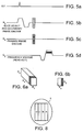
- FIG 4 consider a slab of volume within the region of good field 5 which it is desired to image.
- the pulse sequence is shown in Figures 5a to 5d.
- an r.f. pulse typically of flip angle between 10 and 50° is applied to the patient of which the region shown in Figure 4 defines a slab, and the resulting echo signals are received while a magnetic field gradient in the y-frequency encode direction is being applied.
- the echo signals which consist of a combination of frequencies, can be analysed by Fourier transformation to detect the distribution of hydrogen nuclei in the y-direction. Accordingly, the y-direction is frequency encoded (Fy) in Figure 4.
- the readout gradient Gy is preceded by a negative lobe to cancel the dephasing of spins produced during the readout portion.
- the other transverse direction, the x-direction is decoded by means of phase encoding, denoted by Px.
- phase encoding denoted by Px.
- Px phase encoding
- the longitudinal position of the particular slice being imaged is determined by the z-gradient ( Figure 5b) but, since this is slab imaging, in fact a contiguous series of slices are encoded, and so the Gz gradient energises hydrogen nuclei in the slab illustrated in Figure 4.
- a series of secondary phase encode gradients are applied, for each primary phase encode increment in the x-direction. That is, the slab excitation pulse Gz is followed by a second gradient pulse in the z-direction which is turned on and then off before read-out takes place, the gradient stepping from a negative value through several increments to a positive value. Typically, there would be 32 such increments. Typically, Tr would be around 10ms.
- the time required would be around 320ms to run through the slice select phase encoding gradients.
- the entire volume would be run through in a period 256 times as long, to allow each of the x phase increments to be executed. In other words, the whole volume shown in Figure 4 would be scanned on this basis in around 80 seconds.
- each echo signal produces a series of points on one vertical line Ky, and a fresh vertical line is produced at each Kz phase encode increment.
- the k-space of Figure 6a is converted to a representation of the distribution of hydrogen nuclei in real space in digital signal processor 13, by separable Fourier transformation along each of the x,y and z axis.
- the point z 3 in Figure 7c also reflects a phase change dependent upon the speed of the couch. It is then merely necessary, using the Fourier shift theorem, to multiply each point in the k-space array of Figure 6a by an appropriate phase correction to take account of the translation of the volume while the data was being collected. If this phase correction is made, then the correction can be performed wholly in k-space.
- the spatial correction discussed with relation to Figure 7c on the other hand requires that the z-dimension is first of all Fourier transformed to real space.
- a description of the use of the Fourier shift theorem used for correction of involuntary motion is magnetic resonance imaging is described in Frequency Domain Simulation of MR Tagging, William R Crum et al, JMRI 1998; 8:1040-1050.
- the volume to be imaged will extend further in the z-direction than the slab of Figure 4.
- the volume of the patient originally lying between z-coordinates z 1 and z 2 has been translated to z-coordinates z 4 , z 3 .
- the volume of the patient lying between z-coordinates z 1 and z 3 has been imaged, and a fresh volume of the patient between z-coordinates z 3 and z 2 has now entered the volume which is excited (between z 1 and z 2 ). Consequently, after the next scan has been completed, the fresh volume between z 3 and z 2 is imaged, and so on.
- the excitation volume and the speed of translation may be chosen so that point z 3 moves all the way to point z 1 in the time which one scan takes to perform.
- the volume which is fully imaged on each scan is now just a single slice, and there is no overlap between the volume fully imaged on one scan and the volume fully imaged on the next scan. Continuous imaging of a patient on the couch 3 moving through the region of good field takes place, and the result is a continuous seamless length of time 3D image data.
- the invention is particularly applicable to magnets having only a narrow region of good field in the z-direction eg. maximum thickness of 3cms. This would apply particularly to shorter magnets. While an annular magnet has been described, the invention is also applicable to other geometries for example C-magnets and including permanent magnets.
- the invention is of course applicable to slice select and phase encode gradients being in the x or y or oblique directions, with appropriate changes to the motion of the volume to be imaged.
- This invention can also include correction for spatial distortions introduced by main field inhomogeneity and/or gradient non-linearity.
- the correction could take the form of a real space unwarping or a k space-regridding.
Landscapes
- Physics & Mathematics (AREA)
- Health & Medical Sciences (AREA)
- Nuclear Medicine, Radiotherapy & Molecular Imaging (AREA)
- Condensed Matter Physics & Semiconductors (AREA)
- General Physics & Mathematics (AREA)
- Vascular Medicine (AREA)
- General Health & Medical Sciences (AREA)
- Radiology & Medical Imaging (AREA)
- Engineering & Computer Science (AREA)
- Signal Processing (AREA)
- High Energy & Nuclear Physics (AREA)
- Magnetic Resonance Imaging Apparatus (AREA)
Applications Claiming Priority (2)
| Application Number | Priority Date | Filing Date | Title |
|---|---|---|---|
| GB9828425A GB2345139A (en) | 1998-12-24 | 1998-12-24 | MRI apparatus with continuous movement of patient |
| GB9828425 | 1998-12-24 |
Publications (3)
| Publication Number | Publication Date |
|---|---|
| EP1024371A2 true EP1024371A2 (de) | 2000-08-02 |
| EP1024371A3 EP1024371A3 (de) | 2000-08-30 |
| EP1024371B1 EP1024371B1 (de) | 2004-12-01 |
Family
ID=10844873
Family Applications (1)
| Application Number | Title | Priority Date | Filing Date |
|---|---|---|---|
| EP99309547A Expired - Lifetime EP1024371B1 (de) | 1998-12-24 | 1999-11-29 | Gerät zur Bilderzeugung mittels magnetischer Kernresonanz |
Country Status (5)
| Country | Link |
|---|---|
| US (1) | US6385478B1 (de) |
| EP (1) | EP1024371B1 (de) |
| JP (1) | JP2000229073A (de) |
| DE (1) | DE69922333T2 (de) |
| GB (1) | GB2345139A (de) |
Cited By (12)
| Publication number | Priority date | Publication date | Assignee | Title |
|---|---|---|---|---|
| WO2003027701A1 (en) * | 2001-09-25 | 2003-04-03 | Wisconsin Alumni Research Foundation | Magnetic resonance angiography using floating table projection imaging |
| EP1363137A2 (de) | 2002-05-17 | 2003-11-19 | GE Medical Systems Global Technology Company LLC | Kompensation nicht-linearer Gradienten in der magnetischen Resonanzbildgebung mit sich bewegender Patientenauflage |
| EP1205760A3 (de) * | 2000-11-09 | 2003-12-03 | The Board Of Trustees Of The Leland Stanford Junior University | Verfahren und Gerät der bildgebenden magnetischen Resonanz zur Abbildung eines Sichtfeldes, das grösser ist als ein homogener Magnetfeldbereich |
| EP1367407A2 (de) | 2002-05-17 | 2003-12-03 | GE Medical Systems Global Technology Company LLC | K-Raum Korrektur von Gradienten-Nichtlinearitäten in der bildgebenden magnetischen Resonanz |
| WO2004027443A1 (en) * | 2002-09-18 | 2004-04-01 | Koninklijke Philips Electronics N.V. | A method of cyclic magnetic resonance imaging |
| DE10301497A1 (de) * | 2003-01-16 | 2004-08-05 | Siemens Ag | Magnetresonanz-Projektionsangiographie mit kontinuierlicher Tischverschiebung |
| WO2004077086A1 (en) | 2003-02-28 | 2004-09-10 | Koninklijke Philips Electronics N.V. | Moving table mri with subsampling |
| NL1021584C2 (nl) * | 2001-10-05 | 2004-09-21 | Ge Med Sys Global Tech Co Llc | Bewegende-tafel-MRI met frequentiecodering in de z-richting. |
| EP1359430A3 (de) * | 2002-05-01 | 2005-04-06 | GE Medical Systems Global Technology Company LLC | Räumliche Kodierung von MR-Daten an einem sich bewegenden Objekt unter Verwendung eines Gradientenfeldes höherer Ordnung |
| WO2006111882A3 (en) * | 2005-04-18 | 2006-11-30 | Koninkl Philips Electronics Nv | Magnetic resonance imaging of a continuously moving object |
| US7224164B2 (en) | 2003-07-07 | 2007-05-29 | Koninklijke Philips Electronics N.V. | Method of monitoring a magnetic field drift of a magnetic resonance imaging apparatus |
| US7405564B2 (en) | 2003-01-20 | 2008-07-29 | Koninklijke Philips Electronics N.V. | Sub-sampled moving table MRI for at least two adjacent fields of view |
Families Citing this family (24)
| Publication number | Priority date | Publication date | Assignee | Title |
|---|---|---|---|---|
| US6795723B1 (en) * | 2000-05-22 | 2004-09-21 | Koninklijke Philips Electronics, N.V. | Interleaved phase encoding acquisition for MRI with controllable artifact suppression and flexible imaging parameter selection |
| JP4515616B2 (ja) * | 2000-09-25 | 2010-08-04 | 株式会社東芝 | 磁気共鳴イメージング装置 |
| WO2003049013A2 (en) * | 2001-12-05 | 2003-06-12 | The Trustees Of The University Of Pennsylvania | Virtual bone biopsy |
| US6897655B2 (en) * | 2001-03-30 | 2005-05-24 | General Electric Company | Moving table MRI with frequency-encoding in the z-direction |
| EP1527733A1 (de) | 2001-04-09 | 2005-05-04 | Mayo Foundation For Medical Education And Research Of The State Of Minnesota | Verfahren zur Erfassung von MRI-Daten während kontinuierlicher Patientenbewegung |
| US6912415B2 (en) | 2001-04-09 | 2005-06-28 | Mayo Foundation For Medical Education And Research | Method for acquiring MRI data from a large field of view using continuous table motion |
| US6617850B2 (en) * | 2001-12-03 | 2003-09-09 | Mayo Foundation For Medical Education And Research | Motion correction of magnetic resonance images using phase difference of two orthogonal acquisitions |
| EP1499908A1 (de) * | 2002-04-08 | 2005-01-26 | Koninklijke Philips Electronics N.V. | Datenverarbeitung zur bildung eines zusammengesetzten objekt-datensatzes aus basis-datensätzen |
| US7009396B2 (en) * | 2002-09-12 | 2006-03-07 | General Electric Company | Method and system for extended volume imaging using MRI with parallel reception |
| US7251520B2 (en) * | 2003-07-08 | 2007-07-31 | General Electric Company | Method and apparatus of slice selective magnetization preparation for moving table MRI |
| EP1743188A1 (de) * | 2004-04-28 | 2007-01-17 | Koninklijke Philips Electronics N.V. | Kontinuierliche mri mit beweglicher tabelle unter benutzung von kontrastmanipulation und/oder aktualisierung von abtastparametern |
| CN1954231A (zh) * | 2004-05-14 | 2007-04-25 | 皇家飞利浦电子股份有限公司 | 移动台mri |
| US7346383B2 (en) | 2004-07-08 | 2008-03-18 | Mayo Foundation For Medical Education And Research | Method for acquiring MRI data from variable fields of view during continuous table motion |
| JP4745642B2 (ja) * | 2004-11-08 | 2011-08-10 | 株式会社日立メディコ | 磁気共鳴イメージング装置 |
| US20090003674A1 (en) * | 2005-04-06 | 2009-01-01 | Koninklijke Philips Electronics N. V. | Sense Mr Parallel Imaging With Continuously Moving Bed |
| JP4685496B2 (ja) * | 2005-04-11 | 2011-05-18 | 株式会社日立メディコ | 磁気共鳴イメージング装置 |
| EP1884190A1 (de) * | 2005-04-28 | 2008-02-06 | Hitachi Medical Corporation | Gerät für die magnetresonanzbilddarstellung |
| CN100589756C (zh) * | 2005-04-28 | 2010-02-17 | 株式会社日立医药 | 磁共振摄影装置 |
| US7423496B2 (en) * | 2005-11-09 | 2008-09-09 | Boston Scientific Scimed, Inc. | Resonator with adjustable capacitance for medical device |
| WO2007122854A1 (ja) * | 2006-04-19 | 2007-11-01 | Hitachi Medical Corporation | 磁気共鳴撮影装置 |
| CN101308202B (zh) * | 2007-05-17 | 2011-04-06 | 西门子公司 | 并行采集图像重建的方法和装置 |
| DE102007027170A1 (de) * | 2007-06-13 | 2008-12-18 | Siemens Ag | Magnet-Resonanz-Gerät und Verfahren zur Durchführung einer Magnet-Resonanz-Untersuchung |
| US8320647B2 (en) | 2007-11-20 | 2012-11-27 | Olea Medical | Method and system for processing multiple series of biological images obtained from a patient |
| DE102008029897B4 (de) * | 2008-06-24 | 2017-12-28 | Siemens Healthcare Gmbh | Verfahren zur Erfassung von MR-Daten eines Messobjektes bei einer MR-Untersuchung in einer Magnetresonanzanlage und entsprechend ausgestaltete Magnetresonanzanlage |
Family Cites Families (8)
| Publication number | Priority date | Publication date | Assignee | Title |
|---|---|---|---|---|
| DE430322C (de) | 1926-06-15 | Rudolf Meckel | Mischtrommel mit oben offenem zylindrischem Trommelmantel und an der schraeg-liegenden Drehachse befestigtem Boden | |
| US4354499A (en) * | 1978-11-20 | 1982-10-19 | Damadian Raymond V | Apparatus and method for nuclear magnetic resonance scanning and mapping |
| DE3124435A1 (de) * | 1981-06-22 | 1983-01-20 | Siemens AG, 1000 Berlin und 8000 München | Geraet zur erzeugung von bildern eines untersuchungsobjektes |
| US4770182A (en) * | 1986-11-26 | 1988-09-13 | Fonar Corporation | NMR screening method |
| DE3938370A1 (de) * | 1989-11-18 | 1991-05-23 | Philips Patentverwaltung | Kernspintomographieverfahren und kernspintomograph zur durchfuehrung des verfahrens |
| DE59406859D1 (de) * | 1993-03-06 | 1998-10-15 | Philips Patentverwaltung | MR-Verfahren zur zwei- oder dreidimensionalen Abbildung eines Untersuchungsbereichs und Anordnung zur Durchführung des Verfahrens |
| US5423315A (en) * | 1993-11-22 | 1995-06-13 | Picker International, Inc. | Magnetic resonance imaging system with thin cylindrical uniform field volume and moving subjects |
| JP3526350B2 (ja) * | 1994-08-08 | 2004-05-10 | 株式会社東芝 | 磁気共鳴イメージング装置 |
-
1998
- 1998-12-24 GB GB9828425A patent/GB2345139A/en not_active Withdrawn
-
1999
- 1999-11-29 DE DE69922333T patent/DE69922333T2/de not_active Expired - Fee Related
- 1999-11-29 EP EP99309547A patent/EP1024371B1/de not_active Expired - Lifetime
- 1999-12-21 US US09/469,067 patent/US6385478B1/en not_active Expired - Fee Related
- 1999-12-24 JP JP11366593A patent/JP2000229073A/ja active Pending
Cited By (22)
| Publication number | Priority date | Publication date | Assignee | Title |
|---|---|---|---|---|
| EP1205760A3 (de) * | 2000-11-09 | 2003-12-03 | The Board Of Trustees Of The Leland Stanford Junior University | Verfahren und Gerät der bildgebenden magnetischen Resonanz zur Abbildung eines Sichtfeldes, das grösser ist als ein homogener Magnetfeldbereich |
| WO2003027701A1 (en) * | 2001-09-25 | 2003-04-03 | Wisconsin Alumni Research Foundation | Magnetic resonance angiography using floating table projection imaging |
| US6671536B2 (en) | 2001-09-25 | 2003-12-30 | Wisconsin Alumni Research Foundation | Magnetic resonance angiography using floating table projection imaging |
| NL1021584C2 (nl) * | 2001-10-05 | 2004-09-21 | Ge Med Sys Global Tech Co Llc | Bewegende-tafel-MRI met frequentiecodering in de z-richting. |
| US7558613B2 (en) | 2002-05-01 | 2009-07-07 | General Electric Company | Spatial encoding MR data of a moving subject using a higher-order gradient field |
| EP1359430A3 (de) * | 2002-05-01 | 2005-04-06 | GE Medical Systems Global Technology Company LLC | Räumliche Kodierung von MR-Daten an einem sich bewegenden Objekt unter Verwendung eines Gradientenfeldes höherer Ordnung |
| EP2463677A1 (de) * | 2002-05-17 | 2012-06-13 | GE Medical Systems Global Technology Company LLC | Kompensation für Gradienten-Nichtlinearität bei der Magnetresonanzbildgebung mit beweglichem Tisch |
| EP1363137A3 (de) * | 2002-05-17 | 2004-12-22 | GE Medical Systems Global Technology Company LLC | Kompensation nicht-linearer Gradienten in der magnetischen Resonanzbildgebung mit sich bewegender Patientenauflage |
| EP1367407A2 (de) | 2002-05-17 | 2003-12-03 | GE Medical Systems Global Technology Company LLC | K-Raum Korrektur von Gradienten-Nichtlinearitäten in der bildgebenden magnetischen Resonanz |
| EP1363137A2 (de) | 2002-05-17 | 2003-11-19 | GE Medical Systems Global Technology Company LLC | Kompensation nicht-linearer Gradienten in der magnetischen Resonanzbildgebung mit sich bewegender Patientenauflage |
| EP1367407A3 (de) * | 2002-05-17 | 2005-04-27 | GE Medical Systems Global Technology Company LLC | K-Raum Korrektur von Gradienten-Nichtlinearitäten in der bildgebenden magnetischen Resonanz |
| US7496396B2 (en) | 2002-09-18 | 2009-02-24 | Koninklijke Philips Electronics N. V. | Method of cyclic magnetic resonance imaging |
| WO2004027443A1 (en) * | 2002-09-18 | 2004-04-01 | Koninklijke Philips Electronics N.V. | A method of cyclic magnetic resonance imaging |
| CN100504433C (zh) * | 2002-09-18 | 2009-06-24 | 皇家飞利浦电子股份有限公司 | 循环磁共振成像的系统和方法 |
| US6870367B2 (en) | 2003-01-16 | 2005-03-22 | Siemens Aktiengesellschaft | Magnetic resonance imaging (MRI) with continuous table motion |
| DE10301497A1 (de) * | 2003-01-16 | 2004-08-05 | Siemens Ag | Magnetresonanz-Projektionsangiographie mit kontinuierlicher Tischverschiebung |
| DE10301497B4 (de) * | 2003-01-16 | 2013-12-24 | Siemens Aktiengesellschaft | Magnetresonanz-Projektionsangiographie-Verfahren mit kontinuierlicher Tischverschiebung sowie MRT-Gerät zur Durchführung des Verfahrens |
| US7405564B2 (en) | 2003-01-20 | 2008-07-29 | Koninklijke Philips Electronics N.V. | Sub-sampled moving table MRI for at least two adjacent fields of view |
| US7417429B2 (en) | 2003-02-28 | 2008-08-26 | Koninklijke Philips Electronics N.V. | Moving table MRI with subsampling in parallel |
| WO2004077086A1 (en) | 2003-02-28 | 2004-09-10 | Koninklijke Philips Electronics N.V. | Moving table mri with subsampling |
| US7224164B2 (en) | 2003-07-07 | 2007-05-29 | Koninklijke Philips Electronics N.V. | Method of monitoring a magnetic field drift of a magnetic resonance imaging apparatus |
| WO2006111882A3 (en) * | 2005-04-18 | 2006-11-30 | Koninkl Philips Electronics Nv | Magnetic resonance imaging of a continuously moving object |
Also Published As
| Publication number | Publication date |
|---|---|
| DE69922333T2 (de) | 2005-11-03 |
| EP1024371B1 (de) | 2004-12-01 |
| DE69922333D1 (de) | 2005-01-05 |
| US6385478B1 (en) | 2002-05-07 |
| EP1024371A3 (de) | 2000-08-30 |
| JP2000229073A (ja) | 2000-08-22 |
| GB2345139A (en) | 2000-06-28 |
| GB9828425D0 (en) | 1999-02-17 |
Similar Documents
| Publication | Publication Date | Title |
|---|---|---|
| US6385478B1 (en) | Magnetic resonance imaging apparatus | |
| US4885542A (en) | MRI compensated for spurious NMR frequency/phase shifts caused by spurious changes in magnetic fields during NMR data measurement processes | |
| US7382127B2 (en) | System and method of accelerated MR propeller imaging | |
| JP3544782B2 (ja) | 磁気共鳴診断装置 | |
| JP6084573B2 (ja) | マルチポイントディクソン技術を用いるmr撮像 | |
| US6411089B1 (en) | Two-dimensional phase-conjugate symmetry reconstruction for 3d spin-warp, echo-planar and echo-volume magnetic resonance imaging | |
| CN101484823B (zh) | 磁共振成像设备和方法 | |
| EP1391746B1 (de) | Parallele Magnetresonanzbildgebung unter Verwendung von Navigator-Echosignalen | |
| US7034530B2 (en) | Technique for simultaneous acquisition of multiple independent MR imaging volumes with optimization of magnetic field homogeneity for spin preparation | |
| EP0329299B1 (de) | Apparat und Verfahren zur Bilderzeugung mittels magnetischer Resonanz | |
| EP2496954B1 (de) | MR-Bildgebung mithilfe von Navigatoren | |
| US20010043068A1 (en) | Method for parallel spatial encoded MRI and apparatus, systems and other methods related thereto | |
| US20070229075A1 (en) | Magnetic resonance imaging apparatus and magnetic resonance imaging method | |
| US6404196B1 (en) | Method for correction of MRI motion artifacts and main field fluctuation | |
| JP4072879B2 (ja) | 核磁気共鳴撮影装置 | |
| CN109716155A (zh) | 具有迪克逊型水/脂肪分离的mr成像 | |
| EP0372814B1 (de) | Vorrichtung zur Bilderzeugung mittels magnetischer Resonanz | |
| US7395108B2 (en) | System for concurrent MRI imaging and magnetic field homogeneity measurement | |
| EP3688479B1 (de) | Magnetresonanzbildgebung mit wasser-fett-trennung nach dixon-verfahren mit verbesserter fettverschiebungskorrektur | |
| CN116635733A (zh) | Dixon型水/脂肪分离MR成像 | |
| JPH09154831A (ja) | Mrイメージング方法及びmri装置 | |
| WO2024236314A1 (en) | Method of image generation by mri using epi | |
| Zhu et al. | Extended-FOV magnetic resonance imaging with table translation and frequency cycling |
Legal Events
| Date | Code | Title | Description |
|---|---|---|---|
| PUAI | Public reference made under article 153(3) epc to a published international application that has entered the european phase |
Free format text: ORIGINAL CODE: 0009012 |
|
| PUAL | Search report despatched |
Free format text: ORIGINAL CODE: 0009013 |
|
| AK | Designated contracting states |
Kind code of ref document: A2 Designated state(s): DE FR NL |
|
| AX | Request for extension of the european patent |
Free format text: AL;LT;LV;MK;RO;SI |
|
| AK | Designated contracting states |
Kind code of ref document: A3 Designated state(s): AT BE CH CY DE DK ES FI FR GB GR IE IT LI LU MC NL PT SE |
|
| AX | Request for extension of the european patent |
Free format text: AL;LT;LV;MK;RO;SI |
|
| RIC1 | Information provided on ipc code assigned before grant |
Free format text: 7G 01R 33/56 A, 7G 01R 33/48 B, 7G 01R 33/54 B |
|
| 17P | Request for examination filed |
Effective date: 20010214 |
|
| AKX | Designation fees paid |
Free format text: DE FR NL |
|
| RAP1 | Party data changed (applicant data changed or rights of an application transferred) |
Owner name: PHILIPS MEDICAL SYSTEMS (CLEVELAND), INC. |
|
| 17Q | First examination report despatched |
Effective date: 20030326 |
|
| GRAP | Despatch of communication of intention to grant a patent |
Free format text: ORIGINAL CODE: EPIDOSNIGR1 |
|
| GRAS | Grant fee paid |
Free format text: ORIGINAL CODE: EPIDOSNIGR3 |
|
| GRAA | (expected) grant |
Free format text: ORIGINAL CODE: 0009210 |
|
| AK | Designated contracting states |
Kind code of ref document: B1 Designated state(s): DE FR NL |
|
| PG25 | Lapsed in a contracting state [announced via postgrant information from national office to epo] |
Ref country code: NL Free format text: LAPSE BECAUSE OF FAILURE TO SUBMIT A TRANSLATION OF THE DESCRIPTION OR TO PAY THE FEE WITHIN THE PRESCRIBED TIME-LIMIT Effective date: 20041201 |
|
| REF | Corresponds to: |
Ref document number: 69922333 Country of ref document: DE Date of ref document: 20050105 Kind code of ref document: P |
|
| NLV1 | Nl: lapsed or annulled due to failure to fulfill the requirements of art. 29p and 29m of the patents act | ||
| PLBE | No opposition filed within time limit |
Free format text: ORIGINAL CODE: 0009261 |
|
| STAA | Information on the status of an ep patent application or granted ep patent |
Free format text: STATUS: NO OPPOSITION FILED WITHIN TIME LIMIT |
|
| ET | Fr: translation filed | ||
| 26N | No opposition filed |
Effective date: 20050902 |
|
| PGFP | Annual fee paid to national office [announced via postgrant information from national office to epo] |
Ref country code: FR Payment date: 20081125 Year of fee payment: 10 |
|
| PGFP | Annual fee paid to national office [announced via postgrant information from national office to epo] |
Ref country code: DE Payment date: 20090126 Year of fee payment: 10 |
|
| REG | Reference to a national code |
Ref country code: FR Ref legal event code: ST Effective date: 20100730 |
|
| PG25 | Lapsed in a contracting state [announced via postgrant information from national office to epo] |
Ref country code: FR Free format text: LAPSE BECAUSE OF NON-PAYMENT OF DUE FEES Effective date: 20091130 |
|
| PG25 | Lapsed in a contracting state [announced via postgrant information from national office to epo] |
Ref country code: DE Free format text: LAPSE BECAUSE OF NON-PAYMENT OF DUE FEES Effective date: 20100601 |