EP1024335B1 - Rezirkulation einer zwischengelagerten Flüssigkeit beim Wiederanfahren einer Argonsäule - Google Patents
Rezirkulation einer zwischengelagerten Flüssigkeit beim Wiederanfahren einer Argonsäule Download PDFInfo
- Publication number
- EP1024335B1 EP1024335B1 EP00300563A EP00300563A EP1024335B1 EP 1024335 B1 EP1024335 B1 EP 1024335B1 EP 00300563 A EP00300563 A EP 00300563A EP 00300563 A EP00300563 A EP 00300563A EP 1024335 B1 EP1024335 B1 EP 1024335B1
- Authority
- EP
- European Patent Office
- Prior art keywords
- column
- argon
- liquid inventory
- recirculation
- separation
- Prior art date
- Legal status (The legal status is an assumption and is not a legal conclusion. Google has not performed a legal analysis and makes no representation as to the accuracy of the status listed.)
- Revoked
Links
- XKRFYHLGVUSROY-UHFFFAOYSA-N Argon Chemical compound [Ar] XKRFYHLGVUSROY-UHFFFAOYSA-N 0.000 title claims abstract description 222
- 239000007788 liquid Substances 0.000 title claims abstract description 140
- 229910052786 argon Inorganic materials 0.000 title claims abstract description 113
- QVGXLLKOCUKJST-UHFFFAOYSA-N atomic oxygen Chemical compound [O] QVGXLLKOCUKJST-UHFFFAOYSA-N 0.000 title claims abstract description 44
- 239000001301 oxygen Substances 0.000 title claims abstract description 44
- 229910052760 oxygen Inorganic materials 0.000 title claims abstract description 44
- 238000004821 distillation Methods 0.000 claims abstract description 61
- 239000000203 mixture Substances 0.000 claims abstract description 11
- 238000000034 method Methods 0.000 claims description 62
- 230000008569 process Effects 0.000 claims description 55
- 238000000926 separation method Methods 0.000 claims description 46
- IJGRMHOSHXDMSA-UHFFFAOYSA-N Atomic nitrogen Chemical compound N#N IJGRMHOSHXDMSA-UHFFFAOYSA-N 0.000 claims description 38
- 230000000717 retained effect Effects 0.000 claims description 25
- 229910052757 nitrogen Inorganic materials 0.000 claims description 19
- 230000003134 recirculating effect Effects 0.000 claims description 8
- 238000012856 packing Methods 0.000 claims description 5
- 230000008901 benefit Effects 0.000 description 7
- 238000010586 diagram Methods 0.000 description 6
- 238000004519 manufacturing process Methods 0.000 description 6
- 238000010992 reflux Methods 0.000 description 5
- 150000001485 argon Chemical class 0.000 description 4
- 230000003247 decreasing effect Effects 0.000 description 4
- 230000001174 ascending effect Effects 0.000 description 3
- 230000006872 improvement Effects 0.000 description 2
- 239000012535 impurity Substances 0.000 description 2
- 230000014759 maintenance of location Effects 0.000 description 2
- 230000009467 reduction Effects 0.000 description 2
- 230000000630 rising effect Effects 0.000 description 2
- 238000004088 simulation Methods 0.000 description 2
- 238000013459 approach Methods 0.000 description 1
- 230000000052 comparative effect Effects 0.000 description 1
- 230000009977 dual effect Effects 0.000 description 1
- 230000000977 initiatory effect Effects 0.000 description 1
- 238000012986 modification Methods 0.000 description 1
- 230000004048 modification Effects 0.000 description 1
- 238000012545 processing Methods 0.000 description 1
- 238000000746 purification Methods 0.000 description 1
- 230000001052 transient effect Effects 0.000 description 1
Images



Classifications
-
- F—MECHANICAL ENGINEERING; LIGHTING; HEATING; WEAPONS; BLASTING
- F25—REFRIGERATION OR COOLING; COMBINED HEATING AND REFRIGERATION SYSTEMS; HEAT PUMP SYSTEMS; MANUFACTURE OR STORAGE OF ICE; LIQUEFACTION SOLIDIFICATION OF GASES
- F25J—LIQUEFACTION, SOLIDIFICATION OR SEPARATION OF GASES OR GASEOUS OR LIQUEFIED GASEOUS MIXTURES BY PRESSURE AND COLD TREATMENT OR BY BRINGING THEM INTO THE SUPERCRITICAL STATE
- F25J3/00—Processes or apparatus for separating the constituents of gaseous or liquefied gaseous mixtures involving the use of liquefaction or solidification
- F25J3/02—Processes or apparatus for separating the constituents of gaseous or liquefied gaseous mixtures involving the use of liquefaction or solidification by rectification, i.e. by continuous interchange of heat and material between a vapour stream and a liquid stream
- F25J3/04—Processes or apparatus for separating the constituents of gaseous or liquefied gaseous mixtures involving the use of liquefaction or solidification by rectification, i.e. by continuous interchange of heat and material between a vapour stream and a liquid stream for air
- F25J3/04642—Recovering noble gases from air
- F25J3/04648—Recovering noble gases from air argon
- F25J3/04654—Producing crude argon in a crude argon column
- F25J3/04666—Producing crude argon in a crude argon column as a parallel working rectification column of the low pressure column in a dual pressure main column system
- F25J3/04672—Producing crude argon in a crude argon column as a parallel working rectification column of the low pressure column in a dual pressure main column system having a top condenser
- F25J3/04703—Producing crude argon in a crude argon column as a parallel working rectification column of the low pressure column in a dual pressure main column system having a top condenser being arranged in more than one vessel
-
- F—MECHANICAL ENGINEERING; LIGHTING; HEATING; WEAPONS; BLASTING
- F25—REFRIGERATION OR COOLING; COMBINED HEATING AND REFRIGERATION SYSTEMS; HEAT PUMP SYSTEMS; MANUFACTURE OR STORAGE OF ICE; LIQUEFACTION SOLIDIFICATION OF GASES
- F25J—LIQUEFACTION, SOLIDIFICATION OR SEPARATION OF GASES OR GASEOUS OR LIQUEFIED GASEOUS MIXTURES BY PRESSURE AND COLD TREATMENT OR BY BRINGING THEM INTO THE SUPERCRITICAL STATE
- F25J3/00—Processes or apparatus for separating the constituents of gaseous or liquefied gaseous mixtures involving the use of liquefaction or solidification
- F25J3/02—Processes or apparatus for separating the constituents of gaseous or liquefied gaseous mixtures involving the use of liquefaction or solidification by rectification, i.e. by continuous interchange of heat and material between a vapour stream and a liquid stream
- F25J3/04—Processes or apparatus for separating the constituents of gaseous or liquefied gaseous mixtures involving the use of liquefaction or solidification by rectification, i.e. by continuous interchange of heat and material between a vapour stream and a liquid stream for air
- F25J3/04406—Processes or apparatus for separating the constituents of gaseous or liquefied gaseous mixtures involving the use of liquefaction or solidification by rectification, i.e. by continuous interchange of heat and material between a vapour stream and a liquid stream for air using a dual pressure main column system
- F25J3/04412—Processes or apparatus for separating the constituents of gaseous or liquefied gaseous mixtures involving the use of liquefaction or solidification by rectification, i.e. by continuous interchange of heat and material between a vapour stream and a liquid stream for air using a dual pressure main column system in a classical double column flowsheet, i.e. with thermal coupling by a main reboiler-condenser in the bottom of low pressure respectively top of high pressure column
-
- F—MECHANICAL ENGINEERING; LIGHTING; HEATING; WEAPONS; BLASTING
- F25—REFRIGERATION OR COOLING; COMBINED HEATING AND REFRIGERATION SYSTEMS; HEAT PUMP SYSTEMS; MANUFACTURE OR STORAGE OF ICE; LIQUEFACTION SOLIDIFICATION OF GASES
- F25J—LIQUEFACTION, SOLIDIFICATION OR SEPARATION OF GASES OR GASEOUS OR LIQUEFIED GASEOUS MIXTURES BY PRESSURE AND COLD TREATMENT OR BY BRINGING THEM INTO THE SUPERCRITICAL STATE
- F25J3/00—Processes or apparatus for separating the constituents of gaseous or liquefied gaseous mixtures involving the use of liquefaction or solidification
- F25J3/02—Processes or apparatus for separating the constituents of gaseous or liquefied gaseous mixtures involving the use of liquefaction or solidification by rectification, i.e. by continuous interchange of heat and material between a vapour stream and a liquid stream
- F25J3/04—Processes or apparatus for separating the constituents of gaseous or liquefied gaseous mixtures involving the use of liquefaction or solidification by rectification, i.e. by continuous interchange of heat and material between a vapour stream and a liquid stream for air
- F25J3/04472—Processes or apparatus for separating the constituents of gaseous or liquefied gaseous mixtures involving the use of liquefaction or solidification by rectification, i.e. by continuous interchange of heat and material between a vapour stream and a liquid stream for air using the cold from cryogenic liquids produced within the air fractionation unit and stored in internal or intermediate storages
- F25J3/04478—Processes or apparatus for separating the constituents of gaseous or liquefied gaseous mixtures involving the use of liquefaction or solidification by rectification, i.e. by continuous interchange of heat and material between a vapour stream and a liquid stream for air using the cold from cryogenic liquids produced within the air fractionation unit and stored in internal or intermediate storages for controlling purposes, e.g. start-up or back-up procedures
-
- F—MECHANICAL ENGINEERING; LIGHTING; HEATING; WEAPONS; BLASTING
- F25—REFRIGERATION OR COOLING; COMBINED HEATING AND REFRIGERATION SYSTEMS; HEAT PUMP SYSTEMS; MANUFACTURE OR STORAGE OF ICE; LIQUEFACTION SOLIDIFICATION OF GASES
- F25J—LIQUEFACTION, SOLIDIFICATION OR SEPARATION OF GASES OR GASEOUS OR LIQUEFIED GASEOUS MIXTURES BY PRESSURE AND COLD TREATMENT OR BY BRINGING THEM INTO THE SUPERCRITICAL STATE
- F25J3/00—Processes or apparatus for separating the constituents of gaseous or liquefied gaseous mixtures involving the use of liquefaction or solidification
- F25J3/02—Processes or apparatus for separating the constituents of gaseous or liquefied gaseous mixtures involving the use of liquefaction or solidification by rectification, i.e. by continuous interchange of heat and material between a vapour stream and a liquid stream
- F25J3/04—Processes or apparatus for separating the constituents of gaseous or liquefied gaseous mixtures involving the use of liquefaction or solidification by rectification, i.e. by continuous interchange of heat and material between a vapour stream and a liquid stream for air
- F25J3/04642—Recovering noble gases from air
- F25J3/04648—Recovering noble gases from air argon
- F25J3/04654—Producing crude argon in a crude argon column
- F25J3/04666—Producing crude argon in a crude argon column as a parallel working rectification column of the low pressure column in a dual pressure main column system
- F25J3/04672—Producing crude argon in a crude argon column as a parallel working rectification column of the low pressure column in a dual pressure main column system having a top condenser
-
- F—MECHANICAL ENGINEERING; LIGHTING; HEATING; WEAPONS; BLASTING
- F25—REFRIGERATION OR COOLING; COMBINED HEATING AND REFRIGERATION SYSTEMS; HEAT PUMP SYSTEMS; MANUFACTURE OR STORAGE OF ICE; LIQUEFACTION SOLIDIFICATION OF GASES
- F25J—LIQUEFACTION, SOLIDIFICATION OR SEPARATION OF GASES OR GASEOUS OR LIQUEFIED GASEOUS MIXTURES BY PRESSURE AND COLD TREATMENT OR BY BRINGING THEM INTO THE SUPERCRITICAL STATE
- F25J3/00—Processes or apparatus for separating the constituents of gaseous or liquefied gaseous mixtures involving the use of liquefaction or solidification
- F25J3/02—Processes or apparatus for separating the constituents of gaseous or liquefied gaseous mixtures involving the use of liquefaction or solidification by rectification, i.e. by continuous interchange of heat and material between a vapour stream and a liquid stream
- F25J3/04—Processes or apparatus for separating the constituents of gaseous or liquefied gaseous mixtures involving the use of liquefaction or solidification by rectification, i.e. by continuous interchange of heat and material between a vapour stream and a liquid stream for air
- F25J3/04642—Recovering noble gases from air
- F25J3/04648—Recovering noble gases from air argon
- F25J3/04721—Producing pure argon, e.g. recovered from a crude argon column
- F25J3/04727—Producing pure argon, e.g. recovered from a crude argon column using an auxiliary pure argon column for nitrogen rejection
-
- F—MECHANICAL ENGINEERING; LIGHTING; HEATING; WEAPONS; BLASTING
- F25—REFRIGERATION OR COOLING; COMBINED HEATING AND REFRIGERATION SYSTEMS; HEAT PUMP SYSTEMS; MANUFACTURE OR STORAGE OF ICE; LIQUEFACTION SOLIDIFICATION OF GASES
- F25J—LIQUEFACTION, SOLIDIFICATION OR SEPARATION OF GASES OR GASEOUS OR LIQUEFIED GASEOUS MIXTURES BY PRESSURE AND COLD TREATMENT OR BY BRINGING THEM INTO THE SUPERCRITICAL STATE
- F25J3/00—Processes or apparatus for separating the constituents of gaseous or liquefied gaseous mixtures involving the use of liquefaction or solidification
- F25J3/02—Processes or apparatus for separating the constituents of gaseous or liquefied gaseous mixtures involving the use of liquefaction or solidification by rectification, i.e. by continuous interchange of heat and material between a vapour stream and a liquid stream
- F25J3/04—Processes or apparatus for separating the constituents of gaseous or liquefied gaseous mixtures involving the use of liquefaction or solidification by rectification, i.e. by continuous interchange of heat and material between a vapour stream and a liquid stream for air
- F25J3/04763—Start-up or control of the process; Details of the apparatus used
- F25J3/04769—Operation, control and regulation of the process; Instrumentation within the process
- F25J3/04793—Rectification, e.g. columns; Reboiler-condenser
- F25J3/048—Argon recovery
-
- F—MECHANICAL ENGINEERING; LIGHTING; HEATING; WEAPONS; BLASTING
- F25—REFRIGERATION OR COOLING; COMBINED HEATING AND REFRIGERATION SYSTEMS; HEAT PUMP SYSTEMS; MANUFACTURE OR STORAGE OF ICE; LIQUEFACTION SOLIDIFICATION OF GASES
- F25J—LIQUEFACTION, SOLIDIFICATION OR SEPARATION OF GASES OR GASEOUS OR LIQUEFIED GASEOUS MIXTURES BY PRESSURE AND COLD TREATMENT OR BY BRINGING THEM INTO THE SUPERCRITICAL STATE
- F25J3/00—Processes or apparatus for separating the constituents of gaseous or liquefied gaseous mixtures involving the use of liquefaction or solidification
- F25J3/02—Processes or apparatus for separating the constituents of gaseous or liquefied gaseous mixtures involving the use of liquefaction or solidification by rectification, i.e. by continuous interchange of heat and material between a vapour stream and a liquid stream
- F25J3/04—Processes or apparatus for separating the constituents of gaseous or liquefied gaseous mixtures involving the use of liquefaction or solidification by rectification, i.e. by continuous interchange of heat and material between a vapour stream and a liquid stream for air
- F25J3/04763—Start-up or control of the process; Details of the apparatus used
- F25J3/04866—Construction and layout of air fractionation equipments, e.g. valves, machines
- F25J3/04969—Retrofitting or revamping of an existing air fractionation unit
-
- F—MECHANICAL ENGINEERING; LIGHTING; HEATING; WEAPONS; BLASTING
- F25—REFRIGERATION OR COOLING; COMBINED HEATING AND REFRIGERATION SYSTEMS; HEAT PUMP SYSTEMS; MANUFACTURE OR STORAGE OF ICE; LIQUEFACTION SOLIDIFICATION OF GASES
- F25J—LIQUEFACTION, SOLIDIFICATION OR SEPARATION OF GASES OR GASEOUS OR LIQUEFIED GASEOUS MIXTURES BY PRESSURE AND COLD TREATMENT OR BY BRINGING THEM INTO THE SUPERCRITICAL STATE
- F25J2200/00—Processes or apparatus using separation by rectification
- F25J2200/90—Details relating to column internals, e.g. structured packing, gas or liquid distribution
-
- F—MECHANICAL ENGINEERING; LIGHTING; HEATING; WEAPONS; BLASTING
- F25—REFRIGERATION OR COOLING; COMBINED HEATING AND REFRIGERATION SYSTEMS; HEAT PUMP SYSTEMS; MANUFACTURE OR STORAGE OF ICE; LIQUEFACTION SOLIDIFICATION OF GASES
- F25J—LIQUEFACTION, SOLIDIFICATION OR SEPARATION OF GASES OR GASEOUS OR LIQUEFIED GASEOUS MIXTURES BY PRESSURE AND COLD TREATMENT OR BY BRINGING THEM INTO THE SUPERCRITICAL STATE
- F25J2205/00—Processes or apparatus using other separation and/or other processing means
- F25J2205/02—Processes or apparatus using other separation and/or other processing means using simple phase separation in a vessel or drum
-
- F—MECHANICAL ENGINEERING; LIGHTING; HEATING; WEAPONS; BLASTING
- F25—REFRIGERATION OR COOLING; COMBINED HEATING AND REFRIGERATION SYSTEMS; HEAT PUMP SYSTEMS; MANUFACTURE OR STORAGE OF ICE; LIQUEFACTION SOLIDIFICATION OF GASES
- F25J—LIQUEFACTION, SOLIDIFICATION OR SEPARATION OF GASES OR GASEOUS OR LIQUEFIED GASEOUS MIXTURES BY PRESSURE AND COLD TREATMENT OR BY BRINGING THEM INTO THE SUPERCRITICAL STATE
- F25J2235/00—Processes or apparatus involving steps for increasing the pressure or for conveying of liquid process streams
- F25J2235/58—Processes or apparatus involving steps for increasing the pressure or for conveying of liquid process streams the fluid being argon or crude argon
-
- F—MECHANICAL ENGINEERING; LIGHTING; HEATING; WEAPONS; BLASTING
- F25—REFRIGERATION OR COOLING; COMBINED HEATING AND REFRIGERATION SYSTEMS; HEAT PUMP SYSTEMS; MANUFACTURE OR STORAGE OF ICE; LIQUEFACTION SOLIDIFICATION OF GASES
- F25J—LIQUEFACTION, SOLIDIFICATION OR SEPARATION OF GASES OR GASEOUS OR LIQUEFIED GASEOUS MIXTURES BY PRESSURE AND COLD TREATMENT OR BY BRINGING THEM INTO THE SUPERCRITICAL STATE
- F25J2245/00—Processes or apparatus involving steps for recycling of process streams
- F25J2245/58—Processes or apparatus involving steps for recycling of process streams the recycled stream being argon or crude argon
-
- Y—GENERAL TAGGING OF NEW TECHNOLOGICAL DEVELOPMENTS; GENERAL TAGGING OF CROSS-SECTIONAL TECHNOLOGIES SPANNING OVER SEVERAL SECTIONS OF THE IPC; TECHNICAL SUBJECTS COVERED BY FORMER USPC CROSS-REFERENCE ART COLLECTIONS [XRACs] AND DIGESTS
- Y10—TECHNICAL SUBJECTS COVERED BY FORMER USPC
- Y10S—TECHNICAL SUBJECTS COVERED BY FORMER USPC CROSS-REFERENCE ART COLLECTIONS [XRACs] AND DIGESTS
- Y10S62/00—Refrigeration
- Y10S62/923—Inert gas
- Y10S62/924—Argon
Definitions
- the present invention relates to a cryogenic air separation process. More specifically, the present invention relates to a process for restarting a sidearm column used in argon/oxygen separation.
- a common method for recovering argon from air is to use a double column distillation system comprising a higher pressure column and a lower pressure column which are thermally linked with a reboiler/condenser.
- a sidearm rectifier column is attached to the lower pressure column.
- the oxygen product is withdrawn from the bottom of the lower pressure column and at least one nitrogen-enriched stream is withdrawn from the top of the lower pressure column.
- a portion of the vapour rising through the lower pressure column is withdrawn from an intermediate location and passed to the sidearm column.
- This portion which generally contains between 5 mole% and 20 mole% argon, traces of nitrogen, and balance oxygen, is rectified in the sidearm column to produce an argon-enriched stream which is substantially free of oxygen.
- this argon enriched stream is withdrawn from the top of the sidearm column with an oxygen content ranging from 1 ppm to 3 mole% oxygen.
- the rectification in the sidearm column is achieved by providing liquid reflux to the sidearm column via a condenser located at the top of the sidearm column. More than one sidearm column can be present with each column connected to the next vessel in the series by a vapour and liquid stream from the top of the preceding column top to the bottom of the next column.
- the bottom of the first sidearm column is attached to the lower pressure column and the top of the last sidearm column contains a condenser as described above.
- the number of sidearm columns is determined by a desire to limit the total height of the system. The number of columns is based on operating needs in conjunction with overall height limitations.
- the retention of the argon inventory in the sidearm column has been shown in prior art to be important when trying to reduce the time necessary to return the sidearm column to its steady-state conditions. Because the concentration of oxygen at the top of the column can be below 1 ppm, and the concentration at the bottom ranges between 80 mole% and 95 mole% oxygen, when the column's liquid inventory is accumulated it is much richer in argon than the feed stream normally available to the sidearm column.
- DE-A-197 34 482 discloses the practice of not only saving the sidearm column inventory but further storing it in more than one repository.
- the liquid is segregated into more than one repository according to argon concentration so as not to nullify the distribution of the argon already available in the column.
- the stored liquid is returned to the sidearm column in different segments according to the concentration of the more volatile argon. All liquid is returned to the sidearm column as reflux liquid which, unless there is a proper vapour flow rate in the column, will either accumulate in the sump or contaminate the oxygen product in the bottom of the low pressure column.
- This patent illustrates the importance of retaining argon inventory in the sidearm column and of preserving the steady-state concentration profile in order to decrease the time necessary to restart an argon sidearm column.
- EP-A-0949473 (published 13th October 1999 with a filing date of 7th April 1999 and claiming a priority date of 8th April 1998 and designating DE, ES, FR, GB & IT) discloses that the restart time of an argon side arm column can be decreased by collecting liquid inventory in the argon side arm column in the sump during interruption and recirculating this liquid inventory prior to restart of the column. After restart, the recirculation is gradually reduced as normal operation of the column is resumed.
- liquid inventory during interruption is collected from both columns in the sump of the second argon column and is recirculated to the top of both argon columns before or upon restart.
- a process for separating mixtures which comprise oxygen and argon by cryogenic distillation in a distillation system comprised of at least one argon-separation distillation column that produces an oxygen stream and an argon stream from a feed stream consisting essentially of oxygen and argon, wherein during an interruption of flow of said feed stream into the argon-separation column, argon-rich liquid inventory in said column is recirculated to a separation section of said column prior to and during re-startup of said column
- certain restrictions apply for the designated states DE, ES, FR, GB & IT as set forth in the claims for those states.
- the present invention provides cryogenic distillation systems for a process of said first aspect.
- said system comprises at least one argon-separation column; collection means for collecting recirculation liquid inventory (i.e. liquid inventory for recirculation) from an intermediate location of said column; and recirculation means for selectively recirculating argon-rich liquid inventory from said collection means to a separation section of said column.
- recirculation liquid inventory i.e. liquid inventory for recirculation
- Recirculation liquid inventory can be collected during all or only part of the feed stream interruption and recirculated during all or only the latter part of that interruption. Additionally or alternatively, recirculation liquid inventory can be collected and retained in a repository during normal operations of the process and/or during the feed stream interruption for recirculation during all or only the latter part of the feed stream interruption.
- a repository it can be located inside or outside the argon-separation column. In particular, the repository can be the sump of the argon-separation column.
- Recirculation liquid inventory can be collected at any suitable location of the argon-separation column, for example from an intermediate location or from the bottom of said column.
- the recirculation liquid inventory can be reintroduced to the argon-separation column at one or more locations in the column.
- there can be more than one repository with each repository retaining liquid inventory based on its argon concentration for separately recirculation to the argon-separation column in a different location in said column.
- the present invention has particular, but not exclusive, application when the argon-separation column has structured packing or distillation tray internals.
- the present invention is a process for separating mixtures which comprise oxygen, nitrogen, and argon by cryogenic distillation in a distillation system
- the system is comprised of a distillation column that produces a nitrogen-enriched stream, an oxygen-enriched stream, and an argon-enriched stream, and a sidearm column which has a sump and receives the argon-enriched stream from the distillation column.
- the process is characterized in that during an interruption of flow of the argon-enriched stream into the sidearm column, the liquid inventory in the sidearm column is collected at a point above the sump and recirculated through the sidearm column during the interruption and during re-startup of the sidearm column.
- the present invention is a process for separating mixtures which comprise oxygen, nitrogen, and argon by cryogenic distillation in a distillation system
- the system is comprised of a distillation column that produces a nitrogen-enriched stream, an oxygen-enriched stream, and an argon-enriched stream, and a sidearm column which receives the argon-enriched stream from the distillation column.
- the process is characterized in that during an interruption of flow of the argon-enriched stream into the sidearm column, the liquid inventory in the sidearm column is collected and retained during the interruption and is then recirculated through the sidearm column prior to and during re-startup of the sidearm column.
- the present invention teaches efficient and more operable processes for the restarting of an argon sidearm column.
- the invention is applicable to the production of argon with any acceptable oxygen concentration but generally with an oxygen content ranging from ppm levels to 3 mole% oxygen.
- feed containing oxygen, nitrogen, and argon typically air
- argon typically air
- the system comprises at least one distillation column that produces a nitrogen-enriched stream from its top and an oxygen product stream from its bottom.
- the column also produces an argon containing intermediate stream which is passed to a sidearm column.
- the invention involves retaining the argon enriched liquid inventory of the sidearm column upon a processing interruption and then recirculating it continuously to the sidearm column before and during the time the column is restarted.
- the argon-enriched inventory is retained in a number of repositories to preserve the existing argon concentration profile in the sidearm column. Also in this mode, each portion of the retained inventory is recirculated through a different section of the sidearm column. The recirculation sections are chosen based upon the argon concentration of the liquid with liquids of higher argon concentration being added at locations higher in the column.
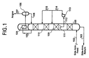
- An argon-containing vapour stream is supplied by a cryogenic distillation process as stream 102.
- This argon containing stream which may contain between 3 mole% to 25 mole% argon (but typically contains between 5 mole% to 15 mole% argon), is passed to the sidearm column 100 as a bottom feed.
- the argon-containing feed to the sidearm column is distilled to reduce the oxygen concentration in the ascending vapour and produces a top vapour 105 and a bottom liquid stream 103.
- the bottom liquid stream is returned to the cryogenic distillation process.
- the top vapour 105 from the sidearm column is partially condensed in reboiler/condenser 104 to form a two-phase stream which is then passed to separator 106 to collect liquid reflux for the sidearm column as stream 108 and the purified argon stream 107.
- separator 106 to collect liquid reflux for the sidearm column as stream 108 and the purified argon stream 107.
- the argon product could be removed from the sidearm column as a liquid.
- the sidearm column could also be split into more than one vessel where each is interconnected by vapour and liquid streams.
- the liquid inventory from the column sections above collector 111 is accumulated by collector 111 and recirculated back to the sidearm column via stream 112 and pump 113 as liquid to one or more upper sections of the sidearm column 100.
- recirculation occurs throughout the shutdown.
- FIG. 1 illustrates the scenario where the liquid is recirculated by pump 113 to two upper sections 109 and 110 via stream 114 and 115.
- the upper sections need not be contiguous as in FIG. 1 but may be separated by one or more other column sections.
- vapour stream 102 Because the flow of vapour stream 102 which is necessary to holdup all of the retained liquid is not present (or is not adequate to hold up all liquid), the liquid returned to the column by streams 114 and 115 will fall over the column internals and again be collected by collector 111. By this means the liquid can be recirculated through the desired section or sections of the column independent of vapour stream 102 or reboiler/condenser 104 which supply the liquid traffic during normal operation.
- the liquid which is accumulated and recirculated is that liquid in the column internals above the collector 111 which would have otherwise run down the column.
- Typical column internals that need an opposing vapour flow to holdup liquid include trays, packing and distributor devices.
- distillation trays or structured packing comprise the column internals, both in the sidearm column(s) and the distillation column.
- the collector 111 can be located at the top or bottom of the column as well as any other intermediate location.
- the embodiment of the invention described in FIG. 1 provides, as one advantage over the prior art processes, that the collection and recirculation of the liquid inventory allows the argon concentration profile to be re-established independent of the vapour stream 102.
- This advantage manifests itself by allowing the liquid hold-up in the column internals to be filled with the highly enriched argon inventory that was retained before any sidearm feed vapour condenses.
- the sidearm feed has a lower argon concentration and thus that which condenses in the upper portion of the column will pollute any inventory that is added subsequently.
- the vapour to be present to condense the liquid concentration profile of the sidearm column can be preserved when adding the retained inventory. Reestablishing the concentration profile quicker allows the column to be restarted more quickly.
- Being able to manipulate the liquid rates in sections of the sidearm column independent of vapour stream 102 and reboiler/condenser 104 could also have advantages for column operation during transient load changes such as increasing or decreasing feed or production rates.
- FIG. 2 illustrates another embodiment of the invention.
- the liquid inventory from the column sections above repository 211 is collected and retained internally in the sidearm column 100 in repository 211.
- the liquid inventory can be retained in repository 211 until it is to be recirculated back to one or more upper sections of sidearm column 100. Recirculation to two sections would occur as described above via stream 112 to pump 113 and then to the two upper sections of the column as streams 114 and 115.
- FIG. 2 has a particular advantage. Because the liquid is retained within the column, there is no need to include extra piping for boiloff from the repository 211 because it has already been included as part of the normal configuration for sidearm column 100. Another particular advantage for this embodiment is that repository 211 can also be used during normal operation to control liquid level in the column, such as when it is configured as the sump of the sidearm column. In that case, the additional capital investment for the inclusion of repository 211 and its accompanying control equipment is greatly reduced because the sidearm column sump can be utilized to store the liquid inventory until it is to be recirculated as described above.
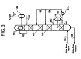
- FIG. 3 shows another embodiment of the invention and represents an alternative to the process of FIG. 2.
- the liquid inventory from the column sections above a collection means is collected as stream 311 and retained external to the sidearm column 100 in repository 312.
- vapour stream 313 must be removed from the top of the repository 312 due to liquid boiloff and fed to column 100.
- the sidearm column liquid inventory can be retained in repository 312 until it is to be recirculated back to one or more upper sections of sidearm column 100 via pump 113 as stream 114 and/or 115.
- the embodiment in FIG. 3 has the particular advantage in that it could be easily retrofitted to an existing sidearm column with a minimal amount of capital investment.
- FIG. 4 shows another embodiment of the invention.
- the liquid inventory from the sidearm column 100 is collected and retained in repositories 411 and 421.
- repositories 411 and 421 any number of repositories may be used.
- these repositories could be either internal or external to the sidearm column.
- the liquid from each repository is recirculated back to the sidearm column 100 separately to one or more different upper column sections.
- the embodiment in FIG. 4 has an advantage in that the multiple repositories allow liquid inventory with different argon concentrations to be saved and recirculated separately. This allows the argon concentration profile in the sidearm column 100 to be re-established with minimal loss of previous separation work.
- each sump can be configured as the internal repositories 411 and 421, thereby greatly decreasing overall capital investment.
- the liquid inventory in each repository can then be recirculated back to the top of the respective vessel from which it was collected before restarting.
- FIG. 5 shows just such an embodiment.
- FIG. 5 shows an argon-containing vapour stream supplied by a cryogenic distillation process as stream 102.
- This argon-containing stream 102 which may contain between 3 mole% to 25 mole% argon, but typically contains between 5 mole% to 15 mole% argon, is passed to a first sidearm column 500 as a bottom feed.
- the argon-containing feed to the sidearm column is distilled to reduce the oxygen concentration in the ascending vapour and produces a top vapour 503 and a bottom liquid stream 502.
- the bottom liquid stream is transferred to the cryogenic distillation process by pump 501 via stream 103.
- the top vapour 503 is passed to the second sidearm column 504 as a bottom feed.
- This argon-containing feed is further distilled to reduce the oxygen concentration in the ascending vapour and produces a top vapour stream 105 and a bottom liquid stream 505.
- the bottom liquid stream 505 is transferred back to the first sidearm column 500 by pump 506 via stream 507, as a top liquid feed.
- the top vapour stream 105 from the second sidearm column 504 is at least partially condensed in reboiler/condenser 104 to form a two-phase stream which is then passed to separator 106 to collect liquid reflux for the second sidearm column 504 as stream 108, and a purified argon stream 509.
- Stream 509 is passed as a feed stream to the argon purification column 510.
- the feed stream 509 is rectified and stripped in column 510 to produce a bottom stream 512 which is purified argon and a top stream 511 which contains more concentrated nitrogen impurities.
- the duty for reboiler 514 is obtained by feed stream 513 which is typically a purified oxygen stream.
- the argon product could be removed from the top of the second sidearm column as a liquid from separator 106.
- the liquid inventory from the second sidearm column 504 is collected in the sump of the column.
- the liquid contained in the sump of the second sidearm column 504 is recirculated back to the second sidearm column 504 to a location above the sump via stream 508. Part of said liquid may also be recirculated back to the first sidearm column 500.
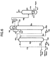
- FIG. 6 shows yet another embodiment of the invention.
- the liquid inventory from the first sidearm column 500 is retained in the sump of column 500 and the liquid inventory from the second sidearm column 504 is retained in the sump of column 504.
- the liquid contained in the sump of the first sidearm column 500 is recirculated back to the first sidearm column 500 to a location above the sump.
- the liquid contained in the sump of the second sidearm column 504 is recirculated via stream 508 back to the first sidearm column 504 to a location above the sump.
- the method according to the invention is further illustrated by the following examples.
- the operation of restarting an argon sidearm column was simulated dynamically for a number of different scenarios.
- the simulations determine the time at which an oxygen impurity of 1 ppm is first obtained at the top of the argon sidearm column after the column is restarted at total reflux. The time to re-establish the full production flow rate of argon product will be longer.
- Example 1 is a comparative simulation of the conventional argon sidearm column restarting procedure where no liquid inventory is retained. In such a case, there is nothing available on restart.
- Examples 2 and 3 illustrate methods according to prior art in which the liquid inventory for a portion of the column is retained and then added back to the section on restart. The retained inventory is added back at a constant rate. The inventory was either vaporized and added to the bottom of the section or returned as a liquid to the top.
- Examples 4 and 5 illustrate methods according to the present invention.
- Example 4 the exact same liquid inventory was retained as was retained in Examples 2 and 3.
- Example 4 an 14% reduction in restart time was achieved over Example 3 due to the re-establishment of the argon concentration profile by liquid recirculation.
- Example 5 retains the liquid inventory in two sections of the sidearm column and recirculates it separately through the respective sections.
- Example 5 a 63.6% reduction in restart is achieved over the base case example. It can be appreciated from these examples that retaining and recirculating the sidearm column inventory can be used to significantly decrease the time necessary to restart an argon sidearm column.
Landscapes
- Engineering & Computer Science (AREA)
- Physics & Mathematics (AREA)
- Mechanical Engineering (AREA)
- Thermal Sciences (AREA)
- General Engineering & Computer Science (AREA)
- Separation By Low-Temperature Treatments (AREA)
- Vaporization, Distillation, Condensation, Sublimation, And Cold Traps (AREA)
- Lubrication Of Internal Combustion Engines (AREA)
Claims (38)
- Verfahren zum Zerlegen von Gemischen, welche Sauerstoff und Argon umfassen, durch kryogene Destillation in einem Destillationssystem, das mindestens eine Argon-Abtrennungs-Destillationskolonne umfasst, welche einen Sauerstoffstrom und einen Argonstrom aus einem Speisestrom erzeugt, der im Wesentlichen aus Sauerstoff und Argon besteht, und bei dem ein argonreicher Flüssigkeitsvorrat nach einer Unterbrechung der Strömung des Speisestroms in die Argon-Abtrennungskolonne zu der Kolonne zurückgeführt wird, dadurch gekennzeichnet, dass während einer Unterbrechung der Strömung des Speisestroms in die Argon-Abtrennungskolonne ein argonreicher Flüssigkeitsvorrat in der Kolonne, vor und während des Wiederanlaufens der Kolonne, zu einem Abtrennungsabschnitt der Kolonne rezirkuliert wird, welche oberhalb der Stelle der Entnahme des Vorrats liegt, wobei Verfahren ausgeschlossen sind, bei denen der Flüssigkeitsvorrat vom Sumpf der Argon-Abtrennungskolonne gesammelt wird, oder, wenn das System zwei Argon-Abtrennungskolonnen hat, gemeinsam aus den Sümpfen jeder Argon-Abtrennungskolonne des Systems, und durch die oder jede der Kolonnen rezirkuliert wird.
- Verfahren nach Anspruch 1, bei dem der Rezirkulations-Flüssigkeitsvorrat während der Unterbrechung gesammelt wird.
- Verfahren nach Anspruch 1 oder Anspruch 2, bei dem der Flüssigkeitsvorrat während der gesamten Unterbrechung rezirkuliert wird.
- Verfahren nach Anspruch 1 oder Anspruch 2, bei dem Rezirkulations-Flüssigkeitsvorrat gesammelt und während des Normalbetriebes des Verfahrens in einem Depot aufbewahrt wird.
- Verfahren nach Anspruch 1 oder Anspruch 2, bei dem Rezirkulations-Flüssigkeitsvorrat während der Unterbrechung in einem Depot gesammelt und aufbewahrt wird, und vor und während des Wiederanlaufens rezirkuliert wird.
- Verfahren nach Anspruch 4 oder Anspruch 5, bei dem das Depot innerhalb der Kolonne angeordnet ist.
- Verfahren nach Anspruch 6, bei dem die Argon-Abtrennungskolonne einen Sumpf hat, der am Boden der Kolonne angeordnet ist, und bei dem das Depot der Sumpf ist.
- Verfahren nach Anspruch 4 oder Anspruch 5, bei dem das Depot außerhalb der Kolonne angeordnet ist.
- Verfahren nach einem der Ansprüche 4 bis 7, bei dem er Rezirkulationsflüssigkeits-Vorrat in einem oder mehreren Depots aufbewahrt wird, wobei jedes Depot einen Flüssigkeitsvorrat basierend auf seiner Argonkonzentration aufbewahrt und jedes der aufbewahrten Flüssigkeitsdepots separat zu der Kolonne an einer unterschiedlichen Stelle in der Argon-Abtrennungskolonne rezirkuliert wird.
- Verfahren nach einem der Ansprüche 1 bis 8, bei dem der Rezirkulationsflüssigkeits-Vorrat wieder an einer Stelle in der Kolonne in die Argon-Abtrenn-ungskolonne eingebracht wird.
- Verfahren nach einem der Ansprüche 1 bis 10, bei dem der Rezirkulationsflüssigkeits-Vorrat an mehr als einer Stelle in der Kolonne wieder in die Argon-Abtrennungskolonne eingebracht wird.
- Verfahren nach einem der vorhergehenden Ansprüche, bei dem der Rezirkulationsflüssigkeits-Vorrat von einer Zwischenstelle der Kolonne gesammelt wird.
- Verfahren nach einem der Ansprüche 1 bis 11, bei dem der Rezirkulationsflüssigkeits-Vorrat vom Boden der Kolonne gesammelt wird.
- Verfahren nach einem der vorhergehenden Ansprüche, bei dem die Argon-Abtrennungskolonne im Inneren eine strukturierte Packung aufweist.
- Verfahren nach einem der Ansprüche 1 bis 13, bei dem die Argon-Abtrennungskolonne im Inneren Destillationsböden aufweist.
- Verfahren nach Anspruch 1, bei dem das Destillationssystem zwei Argon-Abtrennungskolonnen hat, die in Reihe verbunden sind, und Flüssigkeitsvorrat in dem Sumpf der zweiten, nicht aber der ersten Kolonne aufbewahrt und zu sowohl der ersten als auch der zweiten Kolonne vor und während des Anlaufens der ersten Kolonne rezirkuliert wird.
- Verfahren nach Anspruch 1, bei dem das Destillationssystem zwei Argon-Abtrennungskolonnen hat, die in Reihe verbunden sind, und Flüssigkeitsvorrat individuell in dem Sumpf der Kolonnen gesammelt wird, und vor und während des Anlaufens der ersten Kolonne der Flüssigkeitsvorrat aus dem Sumpf der ersten Kolonne individuell zur ersten Kolonne rezirkuliert wird, und der Flüssigkeitsvorrat aus der zweiten Kolonne individuell zu beiden, zur ersten und zweiten Kolonne rezirkuliert wird.
- Verfahren nach einem der vorhergehenden Ansprüche, bei dem der Speisestrom ein argonangereicherter Strom aus einer Destillationskolonne ist, die einen stickstoffangereicherten Strom , einen sauerstoffangereicherten Strom und einen argonangereicherten Strom durch kryogene Destillation eines Gemisches mit Sauerstoff, Stickstoff und Argon herstellt.
- Verfahren nach Anspruch 18, bei dem das Gemisch, das Sauerstoff, Stickstoff und Argon umfasst, Luft ist.
- Verfahren nach Anspruch 18 oder Anspruch 19, zum Zerlegen von Gemischen, die Sauerstoff, Stickstoff und Argon umfassen, durch kryogene Destillation in einem Destillationssystem, wobei das System eine Destillationskolonne aufweist, die einen stickstoffangereicherten Strom, einen sauerstoffangereicherten Strom und einen argonangereicherten Strom herstellt, und eine Nebenkolonne, welche einen Sumpf hat und den argonangereicherten Strom aus der Destillationskolonne aufnimmt, wobei die Nebenkolonne die Argon-Abtrennungs-Destillationskolonne bildet, wobei der argonangereicherte Strom den Speisestrom bildet, der im Wesentlichen aus Sauerstoff und Argon besteht, und wobei der Flüssigkeitsvorrat in der Nebenkolonne an einem Punkt oberhalb des Sumpfes gesammelt wird.
- Verfahren nach Anspruch 18 oder Anspruch 19, zum Zerlegen von Gemischen, die Sauerstoff, Stickstoff und Argon umfassen, durch kryogene Destillation in einem Destillationssystem, wobei das System eine Destillationskolonne aufweist, die einen stickstoffangereicherten Strom, einen sauerstoffangereicherten Strom und einen argonangereicherten Strom herstellt, und eine Nebenkolonne, welche den argonangereicherten Strom aus der Destillationskolonne aufnimmt, wobei die Nebenkolonne die Argon-Abtrennungs-Destillationskolonne bildet, wobei der argonangereicherte Strom den Speisestrom bildet, der im Wesentlichen aus Sauerstoff und Argon besteht, und wobei der Flüssigkeitsvorrat in der Nebenkolonne während der Unterbrechung gesammelt und aufbewahrt wird.
- Verfahren nach einem der vorhergehenden Ansprüche, bei dem der Speisestrom für die Argon-Abtrennungskolonne 3 bis 25 Mol % Argon enthält.
- Verfahren nach Anspruch 22, bei dem die Argonkonzentration 5 bis 15 Mol % beträgt.
- Kryogenes Destillationssystem für ein Verfahren gemäß Anspruch 1, wobei das System umfasst:dadurch gekennzeichnet, dass die Sammeleinrichtung Flüssigkeitsvorrat von einer Zwischenstelle der Kolonne sammelt.mindestens eine Argon-Abtrennungskolonne (100; 500 & 504);eine Sammeleinrichtung (111; 211; 311 & 312; 411 & 421) zum Sammeln eines argonreichen Rezirkulations-Flüssigkeitsvorrates aus der Kolonne; undeine Rezirkulationseinrichtung (112-115; 413-414 & 422-424) zum selektiven Rezirkulieren eines argonreichen Flüssigkeitsvorrates aus der Sammeleinrichtung zu einem Abtrennungsabschnitt der Kolonne;
- Destillationssystem nach Anspruch 24, bei dem die Sammeleinrichtung ein Depot (211; 312; 411 & 421) umfasst, um Rezirkulationsflüssigkeits-Vorrat während des Normalbetriebs des Zerlegungsverfahrens zu sammeln und aufzubewahren.
- Destillationssystem nach Anspruch 24 oder Anspruch 25, bei dem die Sammeleinrichtung ein Depot (211; 312; 411; 421) umfasst, um Rezirkulationsflüssigkeits-Vorrat während der Unterbrechung der Speisestrom-Strömung zu sammeln und aufzubewahren.
- Destillationssystem nach Anspruch 25 oder Anspruch 26, bei dem das Depot (211; 411; 421) innerhalb der Kolonne (100) angeordnet ist.
- Destillationssystem nach Anspruch 25 oder Anspruch 26, bei dem das Depot (312) außerhalb der Kolonne (100) angeordnet ist.
- Destillationssystem nach einem der Ansprüche 25 bis 28, bei dem die Sammeleinrichtung mehr als ein Depot (411 & 421) umfasst, wobei jedes Depot (411 & 421) Flüssigkeitsvorrat basierend auf seiner Argonkonzentration aufbewahrt und die Rezirkulationseinrichtung (412-414 & 422-424) separat Flüssigkeitsvorrat von jedem Depot (411 & 412) zu der Kolonne (100) an einer Stelle in der Kolonne (100) rezirkuliert, die sich von derjenigen unterscheidet, an welcher Flüssigkeitsvorrat von einem anderen Depot (421 & 411) rezirkuliert wird.
- Destillationssystem nach einem der Ansprüche 24 bis 28, bei dem die Rezirkulationseinrichtung (112-114) den rezirkulierten Flüssigkeitsvorrat wieder in die Argon-Abtrennungskolonne (100) an einer Stelle in der Kolonne (100) einbringt.
- Destillationssystem nach einem der Ansprüche 24 bis 29, bei dem die Rezirkulationseinrichtung (112-115; 412-414 & 422-424) die Rezirkulationsflüssigkeit wieder in die Argon-Abtrennungskolonne (100) an mehr als einer Stelle in der Kolonne (100) einbringt.
- Destillationssystem nach einem der Ansprüche 24 bis 31, bei dem die Sammeleinrichtung (112-115) Rezirkulationsflüssigkeits-Vorrat von einer Zwischenstelle der Kolonne (100) sammelt.
- Destillationssystem nach einem der Ansprüche 24 bis 31, bei dem die Argon-Abtrennungskolonne (100) im Inneren strukturierte Packung aufweist.
- Destillationssystem nach einem der Ansprüche 24 bis 32, bei dem die Argon-Abtrennungskolonne (100) im Inneren Destillationsböden aufweist.
- Kryogenes Destillationssystem für ein Verfahren nach Anspruch 16, wobei das System umfasst:eine erste Argon-Abtrennungskolonne (500);eine zweite Argon-Abtrennungskolonne (504), die in Reihe mit der ersten Kolonne (500) verbunden ist;eine Sammeleinrichtung (Sumpf von 504) zum Sammeln von argonreichem Rezirkulations-Flüssigkeitsvorrat aus der zweiten Kolonne (504), nicht aber aus der ersten Kolonne (500);eine Rezirkulationseinrichtung (505-508) zum selektiven Rezirkulieren eines jeweiligen Anteils an Flüssigkeitsvorrat aus der Sammeleinrichtung zu einem jeweiligen Abtrennungsabschnitt sowohl der ersten als auch der zweiten Kolonne.
- Kryogenes Destillationssystem für ein Verfahren nach Anspruch 17, bei dem das System umfasst:eine erste Argon-Abtrennungskolonne (500);eine zweite Argon-Abtrennungskolonne (504), die in Reihe mit der ersten Kolonne (500) verbunden ist;eine erste Sammeleinrichtung (Sumpf von 500) zum Sammeln von Rezirkulationsflüssigkeits-Vorrat aus der ersten Kolonne, nicht aber aus der zweiten Kolonne;einer zweiten Sammeleinrichtung (Sumpf von 504) zum Sammeln von Rezirkulationsflüssigkeits-Vorrat aus der zweiten Kolonne, nicht aber aus der ersten Kolonne;einer ersten Rezirkulationseinrichtung (502, 501-515) zum selektiven Rezirkulieren von Flüssigkeitsvorrat aus der ersten Sammeleinrichtung zu einem Abtrennungsabschnitt der ersten Kolonne;einer zweiten Rezirkulationseinrichtung (505-508), separat von der ersten Rezirkulationseinrichtung, zum selektiven Rezirkulieren eines jeweiligen Anteils an Flüssigkeitsvorrat aus der zweiten Sammeleinrichtung zu einem jeweiligen Abtrennungsabschnitt sowohl der ersten als auch der zweiten Kolonne.
- Destillationssystem nach einem der Ansprüche 24 bis 36, das ferner eine Luftzerlegungs-Destillationskolonne umfasst, welche einen stickstoffangereicherten Strom, einen sauerstoffangereicherten Strom und einen argonangereicherten Strom durch kryogene Destillation herstellt, und eine Einrichtung (102) zum Einspeisen des argonangereicherten Strom in die Argon-Abtrennungskolonne (100).
Applications Claiming Priority (2)
| Application Number | Priority Date | Filing Date | Title |
|---|---|---|---|
| US09/240,257 US6070433A (en) | 1999-01-29 | 1999-01-29 | Recirculation of argon sidearm column for fast response |
| US240257 | 1999-01-29 |
Publications (2)
| Publication Number | Publication Date |
|---|---|
| EP1024335A1 EP1024335A1 (de) | 2000-08-02 |
| EP1024335B1 true EP1024335B1 (de) | 2005-03-30 |
Family
ID=22905806
Family Applications (1)
| Application Number | Title | Priority Date | Filing Date |
|---|---|---|---|
| EP00300563A Revoked EP1024335B1 (de) | 1999-01-29 | 2000-01-26 | Rezirkulation einer zwischengelagerten Flüssigkeit beim Wiederanfahren einer Argonsäule |
Country Status (6)
| Country | Link |
|---|---|
| US (1) | US6070433A (de) |
| EP (1) | EP1024335B1 (de) |
| JP (1) | JP3410416B2 (de) |
| CN (1) | CN100465561C (de) |
| AT (1) | ATE292266T1 (de) |
| DE (1) | DE60019007T2 (de) |
Families Citing this family (6)
| Publication number | Priority date | Publication date | Assignee | Title |
|---|---|---|---|---|
| US6647745B1 (en) | 2002-12-05 | 2003-11-18 | Praxair Technology, Inc. | Method for controlling the operation of a cryogenic rectification plant |
| US7284395B2 (en) * | 2004-09-02 | 2007-10-23 | Praxair Technology, Inc. | Cryogenic air separation plant with reduced liquid drain loss |
| EP2026024A1 (de) * | 2007-07-30 | 2009-02-18 | Linde Aktiengesellschaft | Verfahren und Vorrichtung zur Gewinnung von Argon durch Tieftemperaturzerlegung von Luft |
| US20100024478A1 (en) * | 2008-07-29 | 2010-02-04 | Horst Corduan | Process and device for recovering argon by low-temperature separation of air |
| EP2790804B1 (de) * | 2011-12-16 | 2019-10-16 | Air Products and Chemicals, Inc. | Flüssigkeitsverteiler mit einem mischer |
| US9630123B2 (en) | 2011-12-16 | 2017-04-25 | Air Products And Chemicals, Inc. | Liquid distributor with a mixer |
Family Cites Families (10)
| Publication number | Priority date | Publication date | Assignee | Title |
|---|---|---|---|---|
| DE3436897A1 (de) * | 1984-10-08 | 1986-04-10 | Linde Ag, 6200 Wiesbaden | Verfahren und vorrichtung zum betreiben einer luftzerlegungsanlage |
| US5100447A (en) * | 1990-08-30 | 1992-03-31 | The Boc Group, Inc. | Argon recovery from partial oxidation based ammonia plant purge gases |
| US5255522A (en) * | 1992-02-13 | 1993-10-26 | Air Products And Chemicals, Inc. | Vaporization of liquid oxygen for increased argon recovery |
| US5313800A (en) * | 1993-02-01 | 1994-05-24 | Praxair Technology, Inc. | Process for maximizing the recovery of argon from an air separation system at high argon recovery rates |
| FR2716816B1 (fr) * | 1994-03-02 | 1996-05-03 | Air Liquide | Procédé de redémarrage d'une colonne auxiliaire de séparation argon/oxygène par distillation, et installation correspondante. |
| US5431023A (en) * | 1994-05-13 | 1995-07-11 | Praxair Technology, Inc. | Process for the recovery of oxygen from a cryogenic air separation system |
| GB9617642D0 (en) * | 1996-08-22 | 1996-10-02 | Boc Group Plc | Fractionation column |
| DE19724287A1 (de) * | 1997-06-09 | 1998-02-26 | Linde Ag | Notbetrieb einer Rohargonkolonne |
| DE19734482A1 (de) * | 1997-08-08 | 1998-03-05 | Linde Ag | Verfahren und Vorrichtung zum Betreiben einer Luftzerlegungsanlage mit Argongewinnung |
| US6272884B1 (en) | 1998-04-08 | 2001-08-14 | Praxair Technology, Inc. | Rapid restart system for cryogenic air separation plant |
-
1999
- 1999-01-29 US US09/240,257 patent/US6070433A/en not_active Expired - Lifetime
-
2000
- 2000-01-26 EP EP00300563A patent/EP1024335B1/de not_active Revoked
- 2000-01-26 DE DE60019007T patent/DE60019007T2/de not_active Expired - Lifetime
- 2000-01-26 AT AT00300563T patent/ATE292266T1/de not_active IP Right Cessation
- 2000-01-27 JP JP2000023263A patent/JP3410416B2/ja not_active Expired - Fee Related
- 2000-01-28 CN CNB001019201A patent/CN100465561C/zh not_active Expired - Fee Related
Also Published As
| Publication number | Publication date |
|---|---|
| ATE292266T1 (de) | 2005-04-15 |
| DE60019007D1 (de) | 2005-05-04 |
| CN1264026A (zh) | 2000-08-23 |
| DE60019007T2 (de) | 2006-02-16 |
| US6070433A (en) | 2000-06-06 |
| JP2000227275A (ja) | 2000-08-15 |
| EP1024335A1 (de) | 2000-08-02 |
| JP3410416B2 (ja) | 2003-05-26 |
| CN100465561C (zh) | 2009-03-04 |
Similar Documents
| Publication | Publication Date | Title |
|---|---|---|
| EP0446004B2 (de) | Herstellung von ultrahochreinem Sauerstoff bei der Tieftemperatur-Luftzerlegung | |
| EP0633438B2 (de) | Lufttrennung | |
| EP0636845B1 (de) | Lufttrennung | |
| US5122173A (en) | Cryogenic production of krypton and xenon from air | |
| KR960004311B1 (ko) | 정제 아르곤을 제조하기 위한 저온 정류 방법 | |
| EP0191098B1 (de) | Sauerstoff und argon mit grosser reinheit und verringerter energie | |
| CN1057599C (zh) | 带热耦连氩气塔的低温精馏方法和装置 | |
| US5233838A (en) | Auxiliary column cryogenic rectification system | |
| US5485729A (en) | Air separation | |
| US5590543A (en) | Production of ultra-high purity oxygen from cryogenic air separation plants | |
| JP2000055542A (ja) | 低温空気分離によるアルゴン製造方法 | |
| EP1243883A1 (de) | Luftzerlegung | |
| EP1024335B1 (de) | Rezirkulation einer zwischengelagerten Flüssigkeit beim Wiederanfahren einer Argonsäule | |
| US5715706A (en) | Air separation | |
| US6272884B1 (en) | Rapid restart system for cryogenic air separation plant | |
| CA2108847C (en) | Cryogenic air separation process and apparatus | |
| US5660059A (en) | Air separation | |
| CN1286387A (zh) | 生产甚高纯氧的低温精馏系统 | |
| US6138474A (en) | Argon production control through argon inventory manipulation | |
| US6574988B1 (en) | Process and plant for producing argon by cryogenic distillation | |
| US20080029381A1 (en) | Distillation Installation Comprising Columns With Corrugated-Crossed Structured Packings And Method Of Increasing The Capacity Of A Distillation Installation | |
| CN1135351C (zh) | 生产氩的塔结构和氩的生产方法 | |
| US5682767A (en) | Argon production | |
| CA2034740C (en) | Cryogenic air separation system with hybrid argon column | |
| US5778699A (en) | Process and installation for the production of argon by cryogenic distillation |
Legal Events
| Date | Code | Title | Description |
|---|---|---|---|
| PUAI | Public reference made under article 153(3) epc to a published international application that has entered the european phase |
Free format text: ORIGINAL CODE: 0009012 |
|
| AK | Designated contracting states |
Kind code of ref document: A1 Designated state(s): AT BE CH CY DE DK ES FI FR GB GR IE IT LI LU MC NL PT SE |
|
| AX | Request for extension of the european patent |
Free format text: AL;LT;LV;MK;RO;SI |
|
| 17P | Request for examination filed |
Effective date: 20000911 |
|
| AKX | Designation fees paid |
Free format text: AT BE CH CY DE DK ES FI FR GB GR IE IT LI LU MC NL PT SE |
|
| 17Q | First examination report despatched |
Effective date: 20020503 |
|
| GRAP | Despatch of communication of intention to grant a patent |
Free format text: ORIGINAL CODE: EPIDOSNIGR1 |
|
| GRAS | Grant fee paid |
Free format text: ORIGINAL CODE: EPIDOSNIGR3 |
|
| GRAA | (expected) grant |
Free format text: ORIGINAL CODE: 0009210 |
|
| AK | Designated contracting states |
Kind code of ref document: B1 Designated state(s): AT BE CH CY DE DK ES FI FR GB GR IE IT LI LU MC NL PT SE |
|
| PG25 | Lapsed in a contracting state [announced via postgrant information from national office to epo] |
Ref country code: IT Free format text: LAPSE BECAUSE OF FAILURE TO SUBMIT A TRANSLATION OF THE DESCRIPTION OR TO PAY THE FEE WITHIN THE PRESCRIBED TIME-LIMIT;WARNING: LAPSES OF ITALIAN PATENTS WITH EFFECTIVE DATE BEFORE 2007 MAY HAVE OCCURRED AT ANY TIME BEFORE 2007. THE CORRECT EFFECTIVE DATE MAY BE DIFFERENT FROM THE ONE RECORDED. Effective date: 20050330 Ref country code: NL Free format text: LAPSE BECAUSE OF FAILURE TO SUBMIT A TRANSLATION OF THE DESCRIPTION OR TO PAY THE FEE WITHIN THE PRESCRIBED TIME-LIMIT Effective date: 20050330 Ref country code: LI Free format text: LAPSE BECAUSE OF FAILURE TO SUBMIT A TRANSLATION OF THE DESCRIPTION OR TO PAY THE FEE WITHIN THE PRESCRIBED TIME-LIMIT Effective date: 20050330 Ref country code: AT Free format text: LAPSE BECAUSE OF FAILURE TO SUBMIT A TRANSLATION OF THE DESCRIPTION OR TO PAY THE FEE WITHIN THE PRESCRIBED TIME-LIMIT Effective date: 20050330 Ref country code: CH Free format text: LAPSE BECAUSE OF FAILURE TO SUBMIT A TRANSLATION OF THE DESCRIPTION OR TO PAY THE FEE WITHIN THE PRESCRIBED TIME-LIMIT Effective date: 20050330 Ref country code: BE Free format text: LAPSE BECAUSE OF FAILURE TO SUBMIT A TRANSLATION OF THE DESCRIPTION OR TO PAY THE FEE WITHIN THE PRESCRIBED TIME-LIMIT Effective date: 20050330 Ref country code: FI Free format text: LAPSE BECAUSE OF FAILURE TO SUBMIT A TRANSLATION OF THE DESCRIPTION OR TO PAY THE FEE WITHIN THE PRESCRIBED TIME-LIMIT Effective date: 20050330 |
|
| REG | Reference to a national code |
Ref country code: GB Ref legal event code: FG4D |
|
| REG | Reference to a national code |
Ref country code: CH Ref legal event code: EP |
|
| REF | Corresponds to: |
Ref document number: 60019007 Country of ref document: DE Date of ref document: 20050504 Kind code of ref document: P |
|
| REG | Reference to a national code |
Ref country code: IE Ref legal event code: FG4D |
|
| PG25 | Lapsed in a contracting state [announced via postgrant information from national office to epo] |
Ref country code: DK Free format text: LAPSE BECAUSE OF FAILURE TO SUBMIT A TRANSLATION OF THE DESCRIPTION OR TO PAY THE FEE WITHIN THE PRESCRIBED TIME-LIMIT Effective date: 20050630 Ref country code: GR Free format text: LAPSE BECAUSE OF FAILURE TO SUBMIT A TRANSLATION OF THE DESCRIPTION OR TO PAY THE FEE WITHIN THE PRESCRIBED TIME-LIMIT Effective date: 20050630 |
|
| PG25 | Lapsed in a contracting state [announced via postgrant information from national office to epo] |
Ref country code: ES Free format text: LAPSE BECAUSE OF FAILURE TO SUBMIT A TRANSLATION OF THE DESCRIPTION OR TO PAY THE FEE WITHIN THE PRESCRIBED TIME-LIMIT Effective date: 20050711 |
|
| PG25 | Lapsed in a contracting state [announced via postgrant information from national office to epo] |
Ref country code: PT Free format text: LAPSE BECAUSE OF FAILURE TO SUBMIT A TRANSLATION OF THE DESCRIPTION OR TO PAY THE FEE WITHIN THE PRESCRIBED TIME-LIMIT Effective date: 20050907 |
|
| REG | Reference to a national code |
Ref country code: CH Ref legal event code: PL |
|
| NLV1 | Nl: lapsed or annulled due to failure to fulfill the requirements of art. 29p and 29m of the patents act | ||
| ET | Fr: translation filed | ||
| PLBI | Opposition filed |
Free format text: ORIGINAL CODE: 0009260 |
|
| PG25 | Lapsed in a contracting state [announced via postgrant information from national office to epo] |
Ref country code: IE Free format text: LAPSE BECAUSE OF NON-PAYMENT OF DUE FEES Effective date: 20060126 |
|
| PG25 | Lapsed in a contracting state [announced via postgrant information from national office to epo] |
Ref country code: MC Free format text: LAPSE BECAUSE OF NON-PAYMENT OF DUE FEES Effective date: 20060131 Ref country code: LU Free format text: LAPSE BECAUSE OF NON-PAYMENT OF DUE FEES Effective date: 20060131 |
|
| PLAX | Notice of opposition and request to file observation + time limit sent |
Free format text: ORIGINAL CODE: EPIDOSNOBS2 |
|
| 26 | Opposition filed |
Opponent name: L'AIR LIQUIDE, S.A. A DIRECTOIRE ET CONSEIL DE S Effective date: 20051229 |
|
| PLAF | Information modified related to communication of a notice of opposition and request to file observations + time limit |
Free format text: ORIGINAL CODE: EPIDOSCOBS2 |
|
| PLAF | Information modified related to communication of a notice of opposition and request to file observations + time limit |
Free format text: ORIGINAL CODE: EPIDOSCOBS2 |
|
| PLBB | Reply of patent proprietor to notice(s) of opposition received |
Free format text: ORIGINAL CODE: EPIDOSNOBS3 |
|
| REG | Reference to a national code |
Ref country code: IE Ref legal event code: MM4A |
|
| PG25 | Lapsed in a contracting state [announced via postgrant information from national office to epo] |
Ref country code: SE Free format text: LAPSE BECAUSE OF FAILURE TO SUBMIT A TRANSLATION OF THE DESCRIPTION OR TO PAY THE FEE WITHIN THE PRESCRIBED TIME-LIMIT Effective date: 20050630 |
|
| APAH | Appeal reference modified |
Free format text: ORIGINAL CODE: EPIDOSCREFNO |
|
| APBP | Date of receipt of notice of appeal recorded |
Free format text: ORIGINAL CODE: EPIDOSNNOA2O |
|
| APBQ | Date of receipt of statement of grounds of appeal recorded |
Free format text: ORIGINAL CODE: EPIDOSNNOA3O |
|
| PG25 | Lapsed in a contracting state [announced via postgrant information from national office to epo] |
Ref country code: CY Free format text: LAPSE BECAUSE OF FAILURE TO SUBMIT A TRANSLATION OF THE DESCRIPTION OR TO PAY THE FEE WITHIN THE PRESCRIBED TIME-LIMIT Effective date: 20050330 |
|
| APBU | Appeal procedure closed |
Free format text: ORIGINAL CODE: EPIDOSNNOA9O |
|
| RDAF | Communication despatched that patent is revoked |
Free format text: ORIGINAL CODE: EPIDOSNREV1 |
|
| APBM | Appeal reference recorded |
Free format text: ORIGINAL CODE: EPIDOSNREFNO |
|
| APBP | Date of receipt of notice of appeal recorded |
Free format text: ORIGINAL CODE: EPIDOSNNOA2O |
|
| APAH | Appeal reference modified |
Free format text: ORIGINAL CODE: EPIDOSCREFNO |
|
| APBQ | Date of receipt of statement of grounds of appeal recorded |
Free format text: ORIGINAL CODE: EPIDOSNNOA3O |
|
| PGFP | Annual fee paid to national office [announced via postgrant information from national office to epo] |
Ref country code: GB Payment date: 20131227 Year of fee payment: 15 |
|
| PGFP | Annual fee paid to national office [announced via postgrant information from national office to epo] |
Ref country code: DE Payment date: 20140131 Year of fee payment: 15 |
|
| PGFP | Annual fee paid to national office [announced via postgrant information from national office to epo] |
Ref country code: FR Payment date: 20131223 Year of fee payment: 15 |
|
| REG | Reference to a national code |
Ref country code: DE Ref legal event code: R064 Ref document number: 60019007 Country of ref document: DE Ref country code: DE Ref legal event code: R103 Ref document number: 60019007 Country of ref document: DE |
|
| APBU | Appeal procedure closed |
Free format text: ORIGINAL CODE: EPIDOSNNOA9O |
|
| RDAG | Patent revoked |
Free format text: ORIGINAL CODE: 0009271 |
|
| STAA | Information on the status of an ep patent application or granted ep patent |
Free format text: STATUS: PATENT REVOKED |
|
| 27W | Patent revoked |
Effective date: 20150507 |
|
| GBPR | Gb: patent revoked under art. 102 of the ep convention designating the uk as contracting state |
Effective date: 20150507 |
|
| REG | Reference to a national code |
Ref country code: DE Ref legal event code: R107 Ref document number: 60019007 Country of ref document: DE |