EP0446004B2 - Herstellung von ultrahochreinem Sauerstoff bei der Tieftemperatur-Luftzerlegung - Google Patents
Herstellung von ultrahochreinem Sauerstoff bei der Tieftemperatur-Luftzerlegung Download PDFInfo
- Publication number
- EP0446004B2 EP0446004B2 EP91301790A EP91301790A EP0446004B2 EP 0446004 B2 EP0446004 B2 EP 0446004B2 EP 91301790 A EP91301790 A EP 91301790A EP 91301790 A EP91301790 A EP 91301790A EP 0446004 B2 EP0446004 B2 EP 0446004B2
- Authority
- EP
- European Patent Office
- Prior art keywords
- oxygen
- stream
- column
- distillation column
- process according
- Prior art date
- Legal status (The legal status is an assumption and is not a legal conclusion. Google has not performed a legal analysis and makes no representation as to the accuracy of the status listed.)
- Expired - Lifetime
Links
- 239000001301 oxygen Substances 0.000 title claims description 151
- 229910052760 oxygen Inorganic materials 0.000 title claims description 151
- QVGXLLKOCUKJST-UHFFFAOYSA-N atomic oxygen Chemical compound [O] QVGXLLKOCUKJST-UHFFFAOYSA-N 0.000 title claims description 150
- 238000000926 separation method Methods 0.000 title description 20
- 238000004519 manufacturing process Methods 0.000 title description 8
- IJGRMHOSHXDMSA-UHFFFAOYSA-N Atomic nitrogen Chemical compound N#N IJGRMHOSHXDMSA-UHFFFAOYSA-N 0.000 claims description 119
- 238000004821 distillation Methods 0.000 claims description 65
- 229910052757 nitrogen Inorganic materials 0.000 claims description 60
- 239000007788 liquid Substances 0.000 claims description 56
- 238000000034 method Methods 0.000 claims description 56
- XKRFYHLGVUSROY-UHFFFAOYSA-N Argon Chemical compound [Ar] XKRFYHLGVUSROY-UHFFFAOYSA-N 0.000 claims description 38
- MYMOFIZGZYHOMD-UHFFFAOYSA-N Dioxygen Chemical compound O=O MYMOFIZGZYHOMD-UHFFFAOYSA-N 0.000 claims description 35
- 229910052786 argon Inorganic materials 0.000 claims description 19
- CURLTUGMZLYLDI-UHFFFAOYSA-N Carbon dioxide Chemical compound O=C=O CURLTUGMZLYLDI-UHFFFAOYSA-N 0.000 claims description 18
- 238000010992 reflux Methods 0.000 claims description 18
- 229930195733 hydrocarbon Natural products 0.000 claims description 11
- 150000002430 hydrocarbons Chemical class 0.000 claims description 11
- 229910002092 carbon dioxide Inorganic materials 0.000 claims description 9
- 239000001569 carbon dioxide Substances 0.000 claims description 9
- 239000000356 contaminant Substances 0.000 claims description 8
- 229910052743 krypton Inorganic materials 0.000 claims description 8
- DNNSSWSSYDEUBZ-UHFFFAOYSA-N krypton atom Chemical compound [Kr] DNNSSWSSYDEUBZ-UHFFFAOYSA-N 0.000 claims description 8
- 229910052724 xenon Inorganic materials 0.000 claims description 7
- FHNFHKCVQCLJFQ-UHFFFAOYSA-N xenon atom Chemical compound [Xe] FHNFHKCVQCLJFQ-UHFFFAOYSA-N 0.000 claims description 7
- 239000000203 mixture Substances 0.000 claims description 6
- QJGQUHMNIGDVPM-UHFFFAOYSA-N nitrogen group Chemical group [N] QJGQUHMNIGDVPM-UHFFFAOYSA-N 0.000 claims description 6
- 238000005194 fractionation Methods 0.000 claims description 5
- 239000000047 product Substances 0.000 description 23
- 238000005057 refrigeration Methods 0.000 description 12
- 239000002699 waste material Substances 0.000 description 12
- 239000012535 impurity Substances 0.000 description 7
- 238000010521 absorption reaction Methods 0.000 description 5
- 230000001174 ascending effect Effects 0.000 description 4
- 230000007423 decrease Effects 0.000 description 4
- VNWKTOKETHGBQD-UHFFFAOYSA-N methane Chemical compound C VNWKTOKETHGBQD-UHFFFAOYSA-N 0.000 description 4
- 238000011084 recovery Methods 0.000 description 4
- XLYOFNOQVPJJNP-UHFFFAOYSA-N water Substances O XLYOFNOQVPJJNP-UHFFFAOYSA-N 0.000 description 4
- 238000007084 catalytic combustion reaction Methods 0.000 description 2
- 230000003247 decreasing effect Effects 0.000 description 2
- 239000012263 liquid product Substances 0.000 description 2
- 230000004048 modification Effects 0.000 description 2
- 238000012986 modification Methods 0.000 description 2
- 238000010926 purge Methods 0.000 description 2
- 239000004215 Carbon black (E152) Substances 0.000 description 1
- 230000009286 beneficial effect Effects 0.000 description 1
- 238000009835 boiling Methods 0.000 description 1
- 230000003197 catalytic effect Effects 0.000 description 1
- 238000002485 combustion reaction Methods 0.000 description 1
- 230000006835 compression Effects 0.000 description 1
- 238000007906 compression Methods 0.000 description 1
- 238000009833 condensation Methods 0.000 description 1
- 230000005494 condensation Effects 0.000 description 1
- 230000001627 detrimental effect Effects 0.000 description 1
- 230000009977 dual effect Effects 0.000 description 1
- 230000010354 integration Effects 0.000 description 1
- -1 methane) Chemical class 0.000 description 1
- 150000002829 nitrogen Chemical class 0.000 description 1
- 150000002926 oxygen Chemical class 0.000 description 1
- 230000003134 recirculating effect Effects 0.000 description 1
- 238000001179 sorption measurement Methods 0.000 description 1
Images


Classifications
-
- F—MECHANICAL ENGINEERING; LIGHTING; HEATING; WEAPONS; BLASTING
- F25—REFRIGERATION OR COOLING; COMBINED HEATING AND REFRIGERATION SYSTEMS; HEAT PUMP SYSTEMS; MANUFACTURE OR STORAGE OF ICE; LIQUEFACTION SOLIDIFICATION OF GASES
- F25J—LIQUEFACTION, SOLIDIFICATION OR SEPARATION OF GASES OR GASEOUS OR LIQUEFIED GASEOUS MIXTURES BY PRESSURE AND COLD TREATMENT OR BY BRINGING THEM INTO THE SUPERCRITICAL STATE
- F25J3/00—Processes or apparatus for separating the constituents of gaseous or liquefied gaseous mixtures involving the use of liquefaction or solidification
- F25J3/02—Processes or apparatus for separating the constituents of gaseous or liquefied gaseous mixtures involving the use of liquefaction or solidification by rectification, i.e. by continuous interchange of heat and material between a vapour stream and a liquid stream
- F25J3/04—Processes or apparatus for separating the constituents of gaseous or liquefied gaseous mixtures involving the use of liquefaction or solidification by rectification, i.e. by continuous interchange of heat and material between a vapour stream and a liquid stream for air
- F25J3/04642—Recovering noble gases from air
- F25J3/04648—Recovering noble gases from air argon
- F25J3/04654—Producing crude argon in a crude argon column
- F25J3/04709—Producing crude argon in a crude argon column as an auxiliary column system in at least a dual pressure main column system
-
- F—MECHANICAL ENGINEERING; LIGHTING; HEATING; WEAPONS; BLASTING
- F25—REFRIGERATION OR COOLING; COMBINED HEATING AND REFRIGERATION SYSTEMS; HEAT PUMP SYSTEMS; MANUFACTURE OR STORAGE OF ICE; LIQUEFACTION SOLIDIFICATION OF GASES
- F25J—LIQUEFACTION, SOLIDIFICATION OR SEPARATION OF GASES OR GASEOUS OR LIQUEFIED GASEOUS MIXTURES BY PRESSURE AND COLD TREATMENT OR BY BRINGING THEM INTO THE SUPERCRITICAL STATE
- F25J3/00—Processes or apparatus for separating the constituents of gaseous or liquefied gaseous mixtures involving the use of liquefaction or solidification
- F25J3/02—Processes or apparatus for separating the constituents of gaseous or liquefied gaseous mixtures involving the use of liquefaction or solidification by rectification, i.e. by continuous interchange of heat and material between a vapour stream and a liquid stream
- F25J3/04—Processes or apparatus for separating the constituents of gaseous or liquefied gaseous mixtures involving the use of liquefaction or solidification by rectification, i.e. by continuous interchange of heat and material between a vapour stream and a liquid stream for air
- F25J3/04248—Generation of cold for compensating heat leaks or liquid production, e.g. by Joule-Thompson expansion
- F25J3/04284—Generation of cold for compensating heat leaks or liquid production, e.g. by Joule-Thompson expansion using internal refrigeration by open-loop gas work expansion, e.g. of intermediate or oxygen enriched (waste-)streams
- F25J3/0429—Generation of cold for compensating heat leaks or liquid production, e.g. by Joule-Thompson expansion using internal refrigeration by open-loop gas work expansion, e.g. of intermediate or oxygen enriched (waste-)streams of feed air, e.g. used as waste or product air or expanded into an auxiliary column
- F25J3/04303—Lachmann expansion, i.e. expanded into oxygen producing or low pressure column
-
- F—MECHANICAL ENGINEERING; LIGHTING; HEATING; WEAPONS; BLASTING
- F25—REFRIGERATION OR COOLING; COMBINED HEATING AND REFRIGERATION SYSTEMS; HEAT PUMP SYSTEMS; MANUFACTURE OR STORAGE OF ICE; LIQUEFACTION SOLIDIFICATION OF GASES
- F25J—LIQUEFACTION, SOLIDIFICATION OR SEPARATION OF GASES OR GASEOUS OR LIQUEFIED GASEOUS MIXTURES BY PRESSURE AND COLD TREATMENT OR BY BRINGING THEM INTO THE SUPERCRITICAL STATE
- F25J3/00—Processes or apparatus for separating the constituents of gaseous or liquefied gaseous mixtures involving the use of liquefaction or solidification
- F25J3/02—Processes or apparatus for separating the constituents of gaseous or liquefied gaseous mixtures involving the use of liquefaction or solidification by rectification, i.e. by continuous interchange of heat and material between a vapour stream and a liquid stream
- F25J3/04—Processes or apparatus for separating the constituents of gaseous or liquefied gaseous mixtures involving the use of liquefaction or solidification by rectification, i.e. by continuous interchange of heat and material between a vapour stream and a liquid stream for air
- F25J3/04248—Generation of cold for compensating heat leaks or liquid production, e.g. by Joule-Thompson expansion
- F25J3/04284—Generation of cold for compensating heat leaks or liquid production, e.g. by Joule-Thompson expansion using internal refrigeration by open-loop gas work expansion, e.g. of intermediate or oxygen enriched (waste-)streams
- F25J3/04321—Generation of cold for compensating heat leaks or liquid production, e.g. by Joule-Thompson expansion using internal refrigeration by open-loop gas work expansion, e.g. of intermediate or oxygen enriched (waste-)streams of oxygen
-
- F—MECHANICAL ENGINEERING; LIGHTING; HEATING; WEAPONS; BLASTING
- F25—REFRIGERATION OR COOLING; COMBINED HEATING AND REFRIGERATION SYSTEMS; HEAT PUMP SYSTEMS; MANUFACTURE OR STORAGE OF ICE; LIQUEFACTION SOLIDIFICATION OF GASES
- F25J—LIQUEFACTION, SOLIDIFICATION OR SEPARATION OF GASES OR GASEOUS OR LIQUEFIED GASEOUS MIXTURES BY PRESSURE AND COLD TREATMENT OR BY BRINGING THEM INTO THE SUPERCRITICAL STATE
- F25J3/00—Processes or apparatus for separating the constituents of gaseous or liquefied gaseous mixtures involving the use of liquefaction or solidification
- F25J3/02—Processes or apparatus for separating the constituents of gaseous or liquefied gaseous mixtures involving the use of liquefaction or solidification by rectification, i.e. by continuous interchange of heat and material between a vapour stream and a liquid stream
- F25J3/04—Processes or apparatus for separating the constituents of gaseous or liquefied gaseous mixtures involving the use of liquefaction or solidification by rectification, i.e. by continuous interchange of heat and material between a vapour stream and a liquid stream for air
- F25J3/04406—Processes or apparatus for separating the constituents of gaseous or liquefied gaseous mixtures involving the use of liquefaction or solidification by rectification, i.e. by continuous interchange of heat and material between a vapour stream and a liquid stream for air using a dual pressure main column system
- F25J3/04412—Processes or apparatus for separating the constituents of gaseous or liquefied gaseous mixtures involving the use of liquefaction or solidification by rectification, i.e. by continuous interchange of heat and material between a vapour stream and a liquid stream for air using a dual pressure main column system in a classical double column flowsheet, i.e. with thermal coupling by a main reboiler-condenser in the bottom of low pressure respectively top of high pressure column
-
- F—MECHANICAL ENGINEERING; LIGHTING; HEATING; WEAPONS; BLASTING
- F25—REFRIGERATION OR COOLING; COMBINED HEATING AND REFRIGERATION SYSTEMS; HEAT PUMP SYSTEMS; MANUFACTURE OR STORAGE OF ICE; LIQUEFACTION SOLIDIFICATION OF GASES
- F25J—LIQUEFACTION, SOLIDIFICATION OR SEPARATION OF GASES OR GASEOUS OR LIQUEFIED GASEOUS MIXTURES BY PRESSURE AND COLD TREATMENT OR BY BRINGING THEM INTO THE SUPERCRITICAL STATE
- F25J3/00—Processes or apparatus for separating the constituents of gaseous or liquefied gaseous mixtures involving the use of liquefaction or solidification
- F25J3/02—Processes or apparatus for separating the constituents of gaseous or liquefied gaseous mixtures involving the use of liquefaction or solidification by rectification, i.e. by continuous interchange of heat and material between a vapour stream and a liquid stream
- F25J3/04—Processes or apparatus for separating the constituents of gaseous or liquefied gaseous mixtures involving the use of liquefaction or solidification by rectification, i.e. by continuous interchange of heat and material between a vapour stream and a liquid stream for air
- F25J3/04406—Processes or apparatus for separating the constituents of gaseous or liquefied gaseous mixtures involving the use of liquefaction or solidification by rectification, i.e. by continuous interchange of heat and material between a vapour stream and a liquid stream for air using a dual pressure main column system
- F25J3/0443—A main column system not otherwise provided, e.g. a modified double column flowsheet
-
- F—MECHANICAL ENGINEERING; LIGHTING; HEATING; WEAPONS; BLASTING
- F25—REFRIGERATION OR COOLING; COMBINED HEATING AND REFRIGERATION SYSTEMS; HEAT PUMP SYSTEMS; MANUFACTURE OR STORAGE OF ICE; LIQUEFACTION SOLIDIFICATION OF GASES
- F25J—LIQUEFACTION, SOLIDIFICATION OR SEPARATION OF GASES OR GASEOUS OR LIQUEFIED GASEOUS MIXTURES BY PRESSURE AND COLD TREATMENT OR BY BRINGING THEM INTO THE SUPERCRITICAL STATE
- F25J3/00—Processes or apparatus for separating the constituents of gaseous or liquefied gaseous mixtures involving the use of liquefaction or solidification
- F25J3/02—Processes or apparatus for separating the constituents of gaseous or liquefied gaseous mixtures involving the use of liquefaction or solidification by rectification, i.e. by continuous interchange of heat and material between a vapour stream and a liquid stream
- F25J3/04—Processes or apparatus for separating the constituents of gaseous or liquefied gaseous mixtures involving the use of liquefaction or solidification by rectification, i.e. by continuous interchange of heat and material between a vapour stream and a liquid stream for air
- F25J3/04436—Processes or apparatus for separating the constituents of gaseous or liquefied gaseous mixtures involving the use of liquefaction or solidification by rectification, i.e. by continuous interchange of heat and material between a vapour stream and a liquid stream for air using at least a triple pressure main column system
- F25J3/04454—Processes or apparatus for separating the constituents of gaseous or liquefied gaseous mixtures involving the use of liquefaction or solidification by rectification, i.e. by continuous interchange of heat and material between a vapour stream and a liquid stream for air using at least a triple pressure main column system a main column system not otherwise provided, e.g. serially coupling of columns or more than three pressure levels
-
- F—MECHANICAL ENGINEERING; LIGHTING; HEATING; WEAPONS; BLASTING
- F25—REFRIGERATION OR COOLING; COMBINED HEATING AND REFRIGERATION SYSTEMS; HEAT PUMP SYSTEMS; MANUFACTURE OR STORAGE OF ICE; LIQUEFACTION SOLIDIFICATION OF GASES
- F25J—LIQUEFACTION, SOLIDIFICATION OR SEPARATION OF GASES OR GASEOUS OR LIQUEFIED GASEOUS MIXTURES BY PRESSURE AND COLD TREATMENT OR BY BRINGING THEM INTO THE SUPERCRITICAL STATE
- F25J3/00—Processes or apparatus for separating the constituents of gaseous or liquefied gaseous mixtures involving the use of liquefaction or solidification
- F25J3/02—Processes or apparatus for separating the constituents of gaseous or liquefied gaseous mixtures involving the use of liquefaction or solidification by rectification, i.e. by continuous interchange of heat and material between a vapour stream and a liquid stream
- F25J3/04—Processes or apparatus for separating the constituents of gaseous or liquefied gaseous mixtures involving the use of liquefaction or solidification by rectification, i.e. by continuous interchange of heat and material between a vapour stream and a liquid stream for air
- F25J3/04642—Recovering noble gases from air
- F25J3/04648—Recovering noble gases from air argon
- F25J3/04654—Producing crude argon in a crude argon column
- F25J3/04709—Producing crude argon in a crude argon column as an auxiliary column system in at least a dual pressure main column system
- F25J3/04715—The auxiliary column system simultaneously produces oxygen
-
- F—MECHANICAL ENGINEERING; LIGHTING; HEATING; WEAPONS; BLASTING
- F25—REFRIGERATION OR COOLING; COMBINED HEATING AND REFRIGERATION SYSTEMS; HEAT PUMP SYSTEMS; MANUFACTURE OR STORAGE OF ICE; LIQUEFACTION SOLIDIFICATION OF GASES
- F25J—LIQUEFACTION, SOLIDIFICATION OR SEPARATION OF GASES OR GASEOUS OR LIQUEFIED GASEOUS MIXTURES BY PRESSURE AND COLD TREATMENT OR BY BRINGING THEM INTO THE SUPERCRITICAL STATE
- F25J3/00—Processes or apparatus for separating the constituents of gaseous or liquefied gaseous mixtures involving the use of liquefaction or solidification
- F25J3/02—Processes or apparatus for separating the constituents of gaseous or liquefied gaseous mixtures involving the use of liquefaction or solidification by rectification, i.e. by continuous interchange of heat and material between a vapour stream and a liquid stream
- F25J3/04—Processes or apparatus for separating the constituents of gaseous or liquefied gaseous mixtures involving the use of liquefaction or solidification by rectification, i.e. by continuous interchange of heat and material between a vapour stream and a liquid stream for air
- F25J3/04763—Start-up or control of the process; Details of the apparatus used
- F25J3/04866—Construction and layout of air fractionation equipments, e.g. valves, machines
- F25J3/04872—Vertical layout of cold equipments within in the cold box, e.g. columns, heat exchangers etc.
- F25J3/04878—Side by side arrangement of multiple vessels in a main column system, wherein the vessels are normally mounted one upon the other or forming different sections of the same column
-
- F—MECHANICAL ENGINEERING; LIGHTING; HEATING; WEAPONS; BLASTING
- F25—REFRIGERATION OR COOLING; COMBINED HEATING AND REFRIGERATION SYSTEMS; HEAT PUMP SYSTEMS; MANUFACTURE OR STORAGE OF ICE; LIQUEFACTION SOLIDIFICATION OF GASES
- F25J—LIQUEFACTION, SOLIDIFICATION OR SEPARATION OF GASES OR GASEOUS OR LIQUEFIED GASEOUS MIXTURES BY PRESSURE AND COLD TREATMENT OR BY BRINGING THEM INTO THE SUPERCRITICAL STATE
- F25J2200/00—Processes or apparatus using separation by rectification
- F25J2200/04—Processes or apparatus using separation by rectification in a dual pressure main column system
- F25J2200/06—Processes or apparatus using separation by rectification in a dual pressure main column system in a classical double column flow-sheet, i.e. with thermal coupling by a main reboiler-condenser in the bottom of low pressure respectively top of high pressure column
-
- F—MECHANICAL ENGINEERING; LIGHTING; HEATING; WEAPONS; BLASTING
- F25—REFRIGERATION OR COOLING; COMBINED HEATING AND REFRIGERATION SYSTEMS; HEAT PUMP SYSTEMS; MANUFACTURE OR STORAGE OF ICE; LIQUEFACTION SOLIDIFICATION OF GASES
- F25J—LIQUEFACTION, SOLIDIFICATION OR SEPARATION OF GASES OR GASEOUS OR LIQUEFIED GASEOUS MIXTURES BY PRESSURE AND COLD TREATMENT OR BY BRINGING THEM INTO THE SUPERCRITICAL STATE
- F25J2200/00—Processes or apparatus using separation by rectification
- F25J2200/32—Processes or apparatus using separation by rectification using a side column fed by a stream from the high pressure column
-
- F—MECHANICAL ENGINEERING; LIGHTING; HEATING; WEAPONS; BLASTING
- F25—REFRIGERATION OR COOLING; COMBINED HEATING AND REFRIGERATION SYSTEMS; HEAT PUMP SYSTEMS; MANUFACTURE OR STORAGE OF ICE; LIQUEFACTION SOLIDIFICATION OF GASES
- F25J—LIQUEFACTION, SOLIDIFICATION OR SEPARATION OF GASES OR GASEOUS OR LIQUEFIED GASEOUS MIXTURES BY PRESSURE AND COLD TREATMENT OR BY BRINGING THEM INTO THE SUPERCRITICAL STATE
- F25J2200/00—Processes or apparatus using separation by rectification
- F25J2200/34—Processes or apparatus using separation by rectification using a side column fed by a stream from the low pressure column
-
- F—MECHANICAL ENGINEERING; LIGHTING; HEATING; WEAPONS; BLASTING
- F25—REFRIGERATION OR COOLING; COMBINED HEATING AND REFRIGERATION SYSTEMS; HEAT PUMP SYSTEMS; MANUFACTURE OR STORAGE OF ICE; LIQUEFACTION SOLIDIFICATION OF GASES
- F25J—LIQUEFACTION, SOLIDIFICATION OR SEPARATION OF GASES OR GASEOUS OR LIQUEFIED GASEOUS MIXTURES BY PRESSURE AND COLD TREATMENT OR BY BRINGING THEM INTO THE SUPERCRITICAL STATE
- F25J2200/00—Processes or apparatus using separation by rectification
- F25J2200/50—Processes or apparatus using separation by rectification using multiple (re-)boiler-condensers at different heights of the column
-
- F—MECHANICAL ENGINEERING; LIGHTING; HEATING; WEAPONS; BLASTING
- F25—REFRIGERATION OR COOLING; COMBINED HEATING AND REFRIGERATION SYSTEMS; HEAT PUMP SYSTEMS; MANUFACTURE OR STORAGE OF ICE; LIQUEFACTION SOLIDIFICATION OF GASES
- F25J—LIQUEFACTION, SOLIDIFICATION OR SEPARATION OF GASES OR GASEOUS OR LIQUEFIED GASEOUS MIXTURES BY PRESSURE AND COLD TREATMENT OR BY BRINGING THEM INTO THE SUPERCRITICAL STATE
- F25J2200/00—Processes or apparatus using separation by rectification
- F25J2200/90—Details relating to column internals, e.g. structured packing, gas or liquid distribution
-
- F—MECHANICAL ENGINEERING; LIGHTING; HEATING; WEAPONS; BLASTING
- F25—REFRIGERATION OR COOLING; COMBINED HEATING AND REFRIGERATION SYSTEMS; HEAT PUMP SYSTEMS; MANUFACTURE OR STORAGE OF ICE; LIQUEFACTION SOLIDIFICATION OF GASES
- F25J—LIQUEFACTION, SOLIDIFICATION OR SEPARATION OF GASES OR GASEOUS OR LIQUEFIED GASEOUS MIXTURES BY PRESSURE AND COLD TREATMENT OR BY BRINGING THEM INTO THE SUPERCRITICAL STATE
- F25J2205/00—Processes or apparatus using other separation and/or other processing means
- F25J2205/02—Processes or apparatus using other separation and/or other processing means using simple phase separation in a vessel or drum
-
- F—MECHANICAL ENGINEERING; LIGHTING; HEATING; WEAPONS; BLASTING
- F25—REFRIGERATION OR COOLING; COMBINED HEATING AND REFRIGERATION SYSTEMS; HEAT PUMP SYSTEMS; MANUFACTURE OR STORAGE OF ICE; LIQUEFACTION SOLIDIFICATION OF GASES
- F25J—LIQUEFACTION, SOLIDIFICATION OR SEPARATION OF GASES OR GASEOUS OR LIQUEFIED GASEOUS MIXTURES BY PRESSURE AND COLD TREATMENT OR BY BRINGING THEM INTO THE SUPERCRITICAL STATE
- F25J2215/00—Processes characterised by the type or other details of the product stream
- F25J2215/50—Oxygen or special cases, e.g. isotope-mixtures or low purity O2
- F25J2215/56—Ultra high purity oxygen, i.e. generally more than 99,9% O2
-
- F—MECHANICAL ENGINEERING; LIGHTING; HEATING; WEAPONS; BLASTING
- F25—REFRIGERATION OR COOLING; COMBINED HEATING AND REFRIGERATION SYSTEMS; HEAT PUMP SYSTEMS; MANUFACTURE OR STORAGE OF ICE; LIQUEFACTION SOLIDIFICATION OF GASES
- F25J—LIQUEFACTION, SOLIDIFICATION OR SEPARATION OF GASES OR GASEOUS OR LIQUEFIED GASEOUS MIXTURES BY PRESSURE AND COLD TREATMENT OR BY BRINGING THEM INTO THE SUPERCRITICAL STATE
- F25J2245/00—Processes or apparatus involving steps for recycling of process streams
- F25J2245/02—Recycle of a stream in general, e.g. a by-pass stream
-
- F—MECHANICAL ENGINEERING; LIGHTING; HEATING; WEAPONS; BLASTING
- F25—REFRIGERATION OR COOLING; COMBINED HEATING AND REFRIGERATION SYSTEMS; HEAT PUMP SYSTEMS; MANUFACTURE OR STORAGE OF ICE; LIQUEFACTION SOLIDIFICATION OF GASES
- F25J—LIQUEFACTION, SOLIDIFICATION OR SEPARATION OF GASES OR GASEOUS OR LIQUEFIED GASEOUS MIXTURES BY PRESSURE AND COLD TREATMENT OR BY BRINGING THEM INTO THE SUPERCRITICAL STATE
- F25J2245/00—Processes or apparatus involving steps for recycling of process streams
- F25J2245/58—Processes or apparatus involving steps for recycling of process streams the recycled stream being argon or crude argon
-
- F—MECHANICAL ENGINEERING; LIGHTING; HEATING; WEAPONS; BLASTING
- F25—REFRIGERATION OR COOLING; COMBINED HEATING AND REFRIGERATION SYSTEMS; HEAT PUMP SYSTEMS; MANUFACTURE OR STORAGE OF ICE; LIQUEFACTION SOLIDIFICATION OF GASES
- F25J—LIQUEFACTION, SOLIDIFICATION OR SEPARATION OF GASES OR GASEOUS OR LIQUEFIED GASEOUS MIXTURES BY PRESSURE AND COLD TREATMENT OR BY BRINGING THEM INTO THE SUPERCRITICAL STATE
- F25J2250/00—Details related to the use of reboiler-condensers
- F25J2250/20—Boiler-condenser with multiple exchanger cores in parallel or with multiple re-boiling or condensing streams
-
- Y—GENERAL TAGGING OF NEW TECHNOLOGICAL DEVELOPMENTS; GENERAL TAGGING OF CROSS-SECTIONAL TECHNOLOGIES SPANNING OVER SEVERAL SECTIONS OF THE IPC; TECHNICAL SUBJECTS COVERED BY FORMER USPC CROSS-REFERENCE ART COLLECTIONS [XRACs] AND DIGESTS
- Y10—TECHNICAL SUBJECTS COVERED BY FORMER USPC
- Y10S—TECHNICAL SUBJECTS COVERED BY FORMER USPC CROSS-REFERENCE ART COLLECTIONS [XRACs] AND DIGESTS
- Y10S62/00—Refrigeration
- Y10S62/923—Inert gas
- Y10S62/924—Argon
-
- Y—GENERAL TAGGING OF NEW TECHNOLOGICAL DEVELOPMENTS; GENERAL TAGGING OF CROSS-SECTIONAL TECHNOLOGIES SPANNING OVER SEVERAL SECTIONS OF THE IPC; TECHNICAL SUBJECTS COVERED BY FORMER USPC CROSS-REFERENCE ART COLLECTIONS [XRACs] AND DIGESTS
- Y10—TECHNICAL SUBJECTS COVERED BY FORMER USPC
- Y10S—TECHNICAL SUBJECTS COVERED BY FORMER USPC CROSS-REFERENCE ART COLLECTIONS [XRACs] AND DIGESTS
- Y10S62/00—Refrigeration
- Y10S62/939—Partial feed stream expansion, air
Definitions
- the present invention is related to a process for the cryogenic distillation of air or oxygen/nitrogen mixtures to produce nitrogen and/or commercial purity oxygen and small quantities of ultra-high purity oxygen.
- US-A-3,363,427 discloses a process for the production of ultra-high purity oxygen from a commercial grade oxygen stream, which typically has an oxygen concentration of about 99.5-99.8 vol%, a small amount of argon as a light impurity and small quantities of heavier impurities consisting of a variety of hydrocarbons (mainly methane), krypton and xenon.
- hydrocarbons are either removed by combustion in a catalytic chamber or as purge liquid from an auxiliary distillation column.
- a catalytic combustion unit When a catalytic combustion unit is not used, multiple distillation columns are used with various heat exchangers and reboiler/condensers to effectuate the separation.
- refrigeration to the system is provided by either importing liquid nitrogen from an external source or using a nitrogen stream from the air separation unit that is recycled back to the air separation unit, thus transferring refrigeration from one point to another.
- This catalytic combustion option requires an additional compressor and heat exchangers.
- US-A-4,560,397 disdoses a process to produce ultra-high purity oxygen and a high pressure nitrogen by cryogenic distillation of air.
- the feed air is fractionated in a high pressure column producing a nitrogen product stream, which is removed from the top of the high pressure column, and a crude liquid oxygen stream, which is removed from the bottom of the high pressure column.
- This crude liquid oxygen stream is laden with all the heavy impurities contained in the feed air and also contains a majority of the argon contained in the feed air.
- a portion of this crude liquid oxygen stream is distilled in a secondary lower pressure column to produce a so called ultra-high purity oxygen.
- US-A-4,755,202 discloses a process to produce ultra-high purity oxygen from an air separation unit using double column cycle.
- an enriched oxygen containing stream oxygen concentration range from 90.0 to 99.9%
- the ascending enriched oxygen containing stream is deaned of heavier components by a descending liquid stream.
- a hydrocarbon-lean enriched oxygen containing stream is removed from the top of the absorption column and is subsequently condensed. A portion of this condensed hydrocarbon-lean stream is recyded as reflux to the absorption column, while the other portion is sent to a stripping column.
- the descending hydrocarbon-lean liquid stream is stripped of the light components, such as argon, to produce an ultra-high purity liquid oxygen product at the bottom.
- a portion of the ultra-high purity liquid oxygen is reboiled to provide a vapor stream for the stripping column.
- This vapor stream is removed from the top of the stripper column and is recovered as a secondary product.
- this process has two undesirable features. The first is that by using a feed oxygen stream from the bottom of the low pressure column which is contaminated with both light and heavy impurities, two distillation columns are required to perform the separation (an absorption column and a stripping column). The second is that the process generates an oxygen containing vapor stream at the top of the shipping column which has an increased argon concentration; it is usually undesirable to have secondary oxygen product stream with decreased oxygen content.
- US-A-4,824,453 disdoses a process to produce ultrahigh purity oxygen in a three-column cryogenic air separation system, in which system oxygen and nitrogen are separated first in a high pressure column and then in a low pressure column and oxygen and argon are separated in an argon sidearm column fed from the low pressure column.
- a side fraction is withdrawn from the argon side arm column and separated by rectification into a ultra-high purity oxygen fraction and a lighter residual fraction.
- Said side fraction contains about 90% oxygen and substantially no nitrogen.
- US-A-4,869,741 disdoses a process to produce ultra-high purity oxygen in which a liquid oxygen containing heavy and light contaminants is used as the feed stream.
- a liquid oxygen containing heavy and light contaminants is used as the feed stream.
- two distillation columns, three reboiler/condensers and a compressor on the recirculating nitrogen stream along with a main heat exchanger are used to effectuate the separation.
- the present invention is an improvement of a conventional cryogenic air separation process for the production of quantities of ultra-high purity oxygen.
- the improvement of the present invention is applicable to any cryogenic process for the fractionation of air using a cryogenic distillation column system comprising at least one distillation column. In these processes, feed air is compressed, cooled to near its dew point and fed to the distillation column system for rectification thereby producing a nitrogen containing overhead and a crude liquid oxygen bottoms.
- the improvement which is for producing an ultra-high purity oxygen product comprising the steps as defined in claims 1 and 18.
- the removed oxygen-containing stream to be stripped can be removed as either a liquid or a vapor stream.
- the heat duty for reboiling the cryogenic stripping/ distillation column can be provided by subcooling at least a portion of the crude liquid oxygen bottoms from the distillation column of the cryogenic distillation column system, or by at least partially condensing a portion of the nitrogen overhead from the distillation column of the cryogenic distillation column system.
- the improvement of the present invention is applicable to one, two and three distillation column systems.
- a feed air stream is compressed, cooled to near its dew point and fed to a high pressure distillation column system for rectification thereby producing a nitrogen containing overhead and a crude liquid oxygen bottoms and the crude liquid oxygen is reduced in pressure, fed to and further fractionated in the a pressure distillation column thereby producing a low pressure nitrogen overhead.
- a feed air stream is compressed, cooled to near its dew point and fed to a high pressure distillation column system for rectification thereby producing a nitrogen containing overhead and a crude liquid oxygen bottoms; the crude liquid oxygen is reduced in pressure, fed to and further fractionated in a low pressure distillation column thereby producing a low pressure nitrogen overhead; and an argon-containing side stream is removed from the low pressure column and rectified in an argon side-arm distillation column thereby producing a crude argon overhead and an enriched oxygen liquid which is returned to the low pressure column.
- the oxygen-containing stream which is essentially free of heavier contaminants can be removed from any of the distillation columns in which primarily oxygen and nitrogen are separated.
- the present invention is particularly suited to a nitrogen generator or single column system, wherein a feed air stream is compressed, cooled to near its dew point and fed to the distillation column system for rectification thereby producing a nitrogen containing overhead and a crude liquid oxygen bottoms.
- the improvement for producing an ultra-high purity oxygen product comprising the steps of: rectifying the crude liquid bottoms thereby producing an oxygen-containing stream which is essentially free of heavier contaminants comprising hydrocarbons, carbon dioxide, xenon and krypton, subsequently stripping the oxygen-containing stream in a cryogenic stripping/distillation column thereby producing an ultra-high purity oxygen product at the bottom of the cryogenic stripping/distillation column, and refluxing said cryogenic stripping/distillation column with a liquid stream from the distillation column which is essentially free of heavier components comprising hydrocarbons, carbon dioxide, xenon and krypton.
- the preferred method for providing heat duty to reboil the cryogenic stripping/distillation column is by condensing at least a portion of the oxygen-containing stream prior to distillation in the cryogenic stripping/distillation column.
- FIGS 3-10 are schematic flowsheets of alternative embodiments of the process of the present invention.
- the embodiments of figures 1 and 2 do not belong to the invention.
- the improvement does not work as a stand-alone unit, but its efficiency and cost effectiveness resides in its novel integration with a cryogenic air separation unit. The improvement is best described in reference to the following two general embodiments.
- the first embodiment essentially is a process for producing an ultra-high purity oxygen product by removing from a location of any fractionation column which is separating nitrogen and oxygen, of an air separation unit a side stream which contains some oxygen, yet is extremely lean in or devoid of heavy components, such as carbon dioxide, krypton, xenon and light hydrocarbons.
- the removed side stream can be removed as either a vapor or liquid.
- Such a location is typically several stages above the air feed to the high pressure column of a single or double column system or several stages above the crude liquid oxygen feed to a low pressure column of a two or three column system.
- This removed heavy contaminant-free oxygen containing stream is subsequently separated by stripping in an auxiliary distillation column to produce an ultra-high purity oxygen product at the bottom of such column.
- the process of the present invention differs from the conventional ultra-high purity oxygen producing processes which all process an oxygen stream which is high in oxygen concentration yet not free of heavy contaminants.
- the oxygen feed stream must be processed to remove the heavy contaminants requiring at least one additional distillation column for this purpose.
- This embodiment #1 of the present invention can be best understood in light of the following discussion of seven variations which are illustrated by the flow-sheets in Figures 1-7. These flowsheets can be divided into two subcategories.
- the first subset draws an oxygen-containing but heavies-free liquid stream from the high pressure and/or the low pressure columns of a two column system and performs separation to recover ultra-high purity oxygen.
- the second subset draws an oxygen-containing but heavies-free vapor stream from the high pressure and/or the low pressure columns and performs a further separation on this stream to recover ultra-high purity oxygen.
- First the subset with liquid withdrawal will be discussed followed by a discussion of the vapor withdrawal subset.
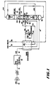
- FIGS 1 and 2 show flowsheets based on a liquid withdrawal from a high pressure column of a single column air separation unit.
- a feed air stream is fed to main air compressor (MAC) 12 via line 10.
- MAC main air compressor
- the feed air stream is after-cooled usually with either an air cooler or a water cooler, and then processed in unit 16 to remove any contaminants which would freeze at cryogenic temperatures, i.e., water and carbon dioxide.
- the processing to remove the water and carbon dioxide can be any known process such as an adsorption mole sieve bed.
- This compressed, water and carbon dioxide free, air is then fed to main heat exchanger 20 via line 18, wherein it is cooled to near its dew point.
- the cooled feed air stream is then fed to the bottom of rectifier 22 via line 21 for separation of the feed air into a nitrogen overhead stream and an oxygen-enriched bottoms liquid.
- the nitrogen overhead is removed from the top of rectifier 22 via line 24 and is then split into two substreams.
- the first substream is fed via line 26 to reboiler/condenser 28 wherein it Is liquefied and then returned to the top of rectifier 22 via line 30 to provide reflux for the rectifier.
- the second substream is removed from rectifier 22 via line 32, warmed in main heat exchanger 20 to provide refrigeration and removed from the process as a gaseous nitrogen product stream via line 34.
- An oxygen-enriched liquid side stream is removed, via line 100, from an intermediate location of rectifier 22.
- the intermediate location is chosen such that the oxygen-enriched side stream has an oxygen concentration less than 35% and is essentially free of heavier components such as hydrocarbons, carbon dioxide, krypton and xenon.
- the oxygen-enriched side stream is then reduced in pressure across a valve and fed to fractionator 102 to be stripped thereby producing a stripper overhead and an ultra-high purity oxygen bottoms liquid.
- the stripper overhead is removed, via line 104, as a waste stream and warmed in heat exchanger 20 to recover refrigeration.
- At least a portion of the ultra-high purity oxygen bottoms liquid is vaporized by indirect heat exchange in reboiler 106 thereby providing reboil to stripper 102.
- Heat duty for reboiler 106 is provided by condensing at least a portion, in line 108, of the nitrogen overhead from the top of rectifier 22 in line 26. After it has been condensed, it is recombined with the condensed nitrogen from condenser 28 and used as reflux for the high pressure column.
- An ultra-high purity oxygen product is removed from the bottom of stripper 102.
- the product can be removed as a gaseous product via line 112 and/or a liquid product via line 114.
- An oxygen-enriched bottoms liquid is removed from the bottom of rectifier 22 via line 38, reduced in pressure and fed to the sump surrounding reboilerlcondenser 28 wherein it is vaporized thereby condensing the nitrogen overhead in line 26.
- the vaporized oxygen-enriched or waste stream is removed from the overhead of the sump area surrounding reboiler/condenser 28 via line 40.
- stream 40 is split into two portions.
- the first portion is fed to main heat exchanger 20 via line 44 wherein it is warmed to recover refrigeration.
- the second portion is combined via line 42 with the warmed first portion in line 44 to form line 46.
- This recombined stream in line 46 is then split into two parts, again to balance the refrigeration requirements of the process.
- the first part in line 50 is expanded in expander 52 and then recombined with the second portion in line 48, after it has been let down in pressure across a valve, to form an expanded waste stream in line 54.
- This expanded waste stream is then fed to and warmed in main heat exchanger 20 to provide refrigeration and is then removed from the process as waste via line 56.
- the stripper waste stream in line 104 can be combined with the expanded waste stream from rectifier 22 in line 54.
- a small purge stream is removed via line 60 from the sump surrounding reboiler/condenser 28 to prevent the build up of hydrocarbons in the liquid in the sump. If needed, a liquid nitrogen product is also recoverable as a fraction of the condensed nitrogen stream.
- Figure 2 is the identical process shown in Figure 1 except that the heat duty for reboiling fractionator 102 is provided by subcooling a portion of the crude liquid oxygen from column 22 instead of condensing a portion of the nitrogen overhead from column 22.
- a portion of the crude liquid oxygen stream, in line 38 is fed, via line 288, to reboiler 286, located in the bottom of stripper 102.
- reboiler 286, the portion is subcooled thereby providing the heat duty required to reboil stripper 102, subsequently reduced in pressure and recombined, via line 290, with the remaining portion of the crude liquid oxygen in line 38.
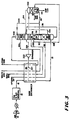
- Figure 3 is an extension of Figure 1 when a double column air separation unit is used.
- an oxygen-enriched liquid side stream is removed, via line 100, from an intermediate location of rectifier 22.
- the intermediate location is chosen such that the oxygen-enriched side stream has an oxygen concentration less than 35% and is essentially free of heavier components such as hydrocarbons.
- the oxygen-enriched side stream is then reduced in pressure across a valve and fed to fractionator 102 to be stripped thereby producing a stripper overhead and an ultra-high purity oxygen bottoms liquid.
- the stripper overhead is removed, via line 104, and fed to an intermediate location of the low pressure column 200.
- the stripper overhead is shown as being fed to the low pressure column at the same location as oxygen-enriched bottom liquid from the high pressure column, it can be fed at any suitable location in the low pressure column. Preferably, it should be fed at a location where the composition of the vapor in the low pressure column is similar to the stripper overhead.
- Heat duty for reboiler 106 is provided by condensing at least a portion, in line 108, of the nitrogen overhead from the top of rectifier 22. After it has been condensed, it is used as reflux for either the high or low pressure distillation columns; such as is shown by line 230.
- An ultra-high purity oxygen product is removed from the bottom of stripper 102.
- the product can be removed as a gaseous product via line 112 and/or a liquid product via line 114.
- heat duty could be provided by condensing a portion of the feed air stream in place of high pressure nitrogen stream.
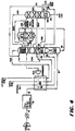
- Figure 4 illustrates the process of the present invention withdrawing a side stream from the low pressure column of a three-column air separation unit.
- a liquid stream is removed, via line 300, from the upper section of low pressure column 200 above the crude oxygen feed, lines 338 and 348, to low pressure column 200.
- This liquid stream in line 300 contains some oxygen, is lean on heavies, and is fed to the top of stripper 302.
- Column 302 can be reboiled by either high pressure gaseous nitrogen, via line 108, or a portion of the air feed from line 21.
- a small argon-rich side stream can be removed via line 350 fed to side arm column 275 producing crude argon via line 276. This cycle is useful for producing small quantities of ultra-high purity oxygen with no additional power requirements.
- a side stream of normal purity gaseous oxygen can be removed via line 360 from stripper 302 several stages from the bottom to decrease L/V in this section and improve recovery of ultra-high purity oxygen. Withdrawal of streams 350 and 360 from stripper 302 is optional. Also, in Figure 4, side arm column 275 is optional.
- FIGS 5-7 show flowsheets based on a vapor stream withdrawal from the high pressure or low pressure column. This vapor stream is extremely lean on heavies yet contains oxygen. A separation is performed on this vapor stream to produce ultra-high purity oxygen. These figures are discussed in further detail, as follows. As with Figures 1-4, common streams and equipment are identified by the same number.
- a vapor stream containing oxygen is withdrawn via line 401 from high pressure column 22 a few theoretical stages above the air feed to high pressure column 22.
- This vapor stream which is essentially free of heavies, is warmed in main heat exchanger 20 and expanded in turbine 403 to provide the refrigeration.
- the exhaust from turbine 403 is fed, via line 407, to auxiliary distillation column 402 to produce ultra-high purity oxygen.
- a pure liquid nitrogen stream, line 231 is used as reflux at the top of column 402.
- This reflux stream, line 231 is originally from the top of high pressure column 22 and is free of heavies; therefore, a pure nitrogen product is produced at the top of column 402.
- any suitable nitrogen rich but heavies-free liquid stream from the high pressure column or the low pressure column could be used as reflux to this column.
- vapor leaving at the top of the auxiliary column would contain quantities of oxygen and could be either fed to the low pressure column for further separation (as shown in Figure 3 or4) or recovered as a secondary product stream.
- the bottom of column 402 is reboiled by a gaseous nitrogen stream, line 108, from the top of the high pressure column.
- a portion of the feed air stream could be used for this purpose.
- an argon-rich stream is withdrawn, via line 460, from column 402 and fed to low pressure column 200.
- This step is optional and is used to reduce the content of argon in the ultra-high purity oxygen.
- either all of the expander exhaust (line 404) can be fed to column 402, via line 407, or a portion of it can be withdrawn and fed, via line 405, to low pressure column 200.
- Figure 6 is similar to Figure 5 with only one difference.
- the gaseous feed to column 402 is not an expanded stream but a vapor stream withdrawn from low pressure column 200, via line 500.
- This vapor stream is withdrawn a few trays above the point where the top-most feed containing heavies is fed to low pressure column 200.
- it is withdrawn a few trays above the point where crude liquid oxygen is fed, via line 38, from the bottom of high pressure column 22 to low pressure column 200.
- the vapor feed to column 402 is withdrawn a few trays above the expanded air feed to column 200. This position of withdrawal is chosen so that the heavies-free liquid reflux descending down low pressure column 200 would have sufficient trays to strip heavies contaminated vapor ascending low pressure column 200.
- Figure 7 is still another variation which can be specially useful when small quantities of ultra-high purity oxygen are required. Similar to Figure 5, a vapor stream containing oxygen but extremely lean on heavies is withdrawn via line 600 from high pressure column 22. Rather than expanding this stream in a turbine, it is used to provide reboil for column 102. The condensed feed stream, in line 602, is reduced in pressure and fed to the top of column 102. The vapor drawn from the top of column 102 via line 104 is fed to a suitable location in the low pressure column. If liquid ultra-high purity oxygen line 114 is to be produced, then an additional liquid feed stream is needed. This stream, which is heavies-free is withdrawn, via line 500, from low pressure column 200 and fed to the top of column 102.
- the concentration of oxygen in this vapor stream will be less than 20%.
- the most likely concentration of oxygen will be in the range of 3% to 15%.
- a concentration of oxygen less than 1% will be undesirable due to extremely low production rates of ultra-high purity oxygen.
- Embodiment #1 discussed the withdrawal of a heavies-free, oxygen-containing stream from the main column systems (high pressure and/or low pressure columns) and then feeding it to an auxiliary column to recover ultrahigh purity oxygen.
- Embodiment #2 is a method whereby a heavies-free but oxygen-containing stream is created from heavies containing crude liquid oxygen of the high pressure column and then fed to an auxiliary column for the production of ultra-high purity oxygen.
- This embodiment #2 decreases the amount of heavies-free but oxygen containing-stream withdrawn from the main column system and thereby decreases the impact of such withdrawal on the nitrogen recovery.
- This embodiment is specially useful for high pressure nitrogen plants.
- Figure 8 shows a modification of a double column dual reboiler high pressure nitrogen generator with waste expander.
- the crude liquid oxygen stream from the bottom of main column 22 (high pressure column) is fed, via line 38, to the top of column 702 operating at a lower pressure.
- Boilup at the bottom of low pressure column 702 is provided by condensing a portion of the nitrogen line 730 from main column 22.
- the vapor from the top of column 702 is recycled via lines 700 and 704 to an intermediate stage of main air compressor 12.
- the unboiled liquid line 720 from the bottom of column 702 is reduced in pressure and reboiled in second reboiler/condenser 28 against condensing nitrogen line 26 from main distillation column 22.
- the vapor line 40 from second reboiler/condenser 28 is warmed and expanded in a turbo-expander to provide the needed refrigeration.
- This process can be modified to produce ultra-high purity oxygen. In the modification, some trays are added as section 750 to column 702 above the crude liquid oxygen feed through line 38 and the top of column 702 is thermally linked with the bottom of the column 102 producing ultra-high purity oxygen through reboiler/condenser 742.
- a liquid stream which is extremely lean on heavies but contains sufficient quantity of oxygen can be withdrawn via line 100 from main nitrogen column 22 and fed to the top section of column 102. Crude liquid oxygen from the bottom of main nitrogen column 22 is fed via line 38 to an intermediate section of column 702. A vapor stream is withdrawn via line 700 from an Intermediate location of column 702 for recyde. The vapor at the top of column 702, line 740, is condensed in reboiler/condenser 742 by providing the heat duty for reboiling column 102. A portion of this condensed stream line 744 is returned via line 746 as reflux to column 702.
- This method of adding additional trays as a top section to column 702 and thermally linking its top with the bottom of column 102 allows one to create an additional heavies-free oxygen source from the crude liquid oxygen. Therefore, for a given quantity of ultra-high purity oxygen to be produced, this embodiment decreases the amount of heavies-free and oxygen containing liquid to be withdrawn via line 100 from main nitrogen column 22. This processing step reduces any detrimental effect on the nitrogen recovery because as the flow of stream 100 is decreased the liquid reflux in the bottom section of main column 22 is increased.
- the essence of this embodiment #2 is that if the crude liquid oxygen is boiled in a reboiler/condenser against a condensing nitrogen stream and the pressure of the nitrogen stream is sufficiently high, then the vaporized stream is at sufficient pressure so that a portion of it can be recondensed against ultra-high purity liquid oxygen at the bottom of the auxiliary column.
- This recondensed liquid is then split into two fractions. One fraction is used as reflux to the short column to provide heavies-free vapor stream to be recondensed against ultra-high purity liquid oxygen. The second fraction forms the feed to the auxiliary column to produce ultra-high purity oxygen.
- Figure 9 nitrogen line 26 from the top of main column 22 is condensed in single reboilerlcondenser 28 (usual single column waste expander nitrogen generator). A few trays 750 are added above reboiler/condenser 28, in essence creating column 702. A portion of the vaporized crude liquid oxygen ascends this column and is deaned of the heavies by the descending liquid. The heavies-free vapor line 740 is condensed in reboiler/condenser 742 by boiling the bottom of column 102.
- a portion of this condensed liquid is sent via line 746 as reflux to column 702 to dean the ascending vapor of the heavies.
- the remaining portion of the condensed liquid line 748 forms a part of the feed to column 102 and is fed at a suitable location in the top section of column 102.
- the vapor overhead is mixed via line 792 with the oxygen-rich waste in line 40 from the bottom of column 702.
- this vapor overhead, line 792 could be let down in pressure and fed to a suitable location in column 102. This will specially be beneficial if the liquid stream is withdrawn via line 100 from main nitrogen column 22 (high pressure column) can be fed to column 102 a few trays above the vapor feed location where 792 is fed so that it can provide the suitable reflux to recover some oxygen from vapor feed 792.
- the concentration of oxygen in stream 740 to be condensed in reboiler/condenser 742 located at the bottom of column 102 will be less than 35%.
- stream 748 recovered from the crude liquid oxygen and then fed as additional feed to column 102 will have oxygen concentration less than 35% and typically is in the range of 5% to 25% oxygen.
- the liquid feed stream 100 withdrawn from the main nitrogen column 22 can have extremely low concentrations of oxygen; so much so that it could be a liquid nitrogen stream withdrawn from the top of column 22. Therefore, stream 748 can be the only source of oxygen to column 102 and liquid feed 100 from main nitrogen column 22 (high pressure column) should be fed a couple of trays above this feed stream. This arrangement reduces the oxygen content in the vapor stream leaving from the top of column 102.
Landscapes
- Engineering & Computer Science (AREA)
- Physics & Mathematics (AREA)
- Mechanical Engineering (AREA)
- Thermal Sciences (AREA)
- General Engineering & Computer Science (AREA)
- Health & Medical Sciences (AREA)
- Emergency Medicine (AREA)
- Separation By Low-Temperature Treatments (AREA)
Claims (23)
- Verfahren zur Fraktionierung von Sauerstoff/Stickstoff-Gemischen durch kryogene Destillation unter Verwendung eines kryogenen Destillationskolonnensystems mit einer Hochdruck-Destillationskolonne und einer Niederdruck-Destillationskolonne, bei dem ein Speiseluftstrom komprimiert, bis nahe an seinen Taupunkt heran gekühlt und der Hochdruck-Destillationskolonne zur Rektifizierung zugeführt wird, wodurch ein Stickstoff enthaltendes Kopfprodukt und ein flüssiges Rohsauerstoff-Bodenprodukt hergestellt werden; wobei das Rohsauerstoff-Bodenprodukt im Druck vermindert und der Niederdruckkolonne zur weiteren Fraktionierung zugeführt wird, um ein Niederdruck-Stickstoff-Kopfprodukt herzustellen; ein Sauerstoff enthaltender Strom von entweder der Hoch- oder der Niederdruckkolonne an einer Stelle abgezogen wird, die über der Luftzufuhr oder der Rohsauerstoff-Bodenproduktzufuhr liegt, der Sauerstoff enthaltende Strom 1 bis 35 % Sauerstoff enthält und im wesentlichen frei von schwereren Verunreinigungen ist, die Kohlenwasserstoffe, Kohlendioxid, Xenon und Krypton umfassen; der Sauerstoff enthaltende Strom nachfolgend in einer kryogenen Stripp-/Destillationskolonne gestrippt wird; und ein ultrahochreines Sauerstoffprodukt vom Boden der kryogenen Stripp-/Destillationskolonne entnommen wird.
- Verfahren nach Anspruch 1, bei dem das Sauerstoff/Stickstoffgemisch Luft ist.
- Verfahren nach einem der vorhergehenden Ansprüche, bei dem der abgezogene, Sauerstoff enthaltende Strom, der gestrippt werden soll, als flüssiger Strom abgezogen wird.
- Verfahren nach Anspruch 3, bei dem die Sauerstoffkonzentration 5 bis 25 % beträgt.
- Verfahren nach Anspruch 1 oder Anspruch 2, bei dem der abgezogene, Sauerstoff enthaltende Strom, der gestrippt werden soll, als dampfförmiger Strom entnommen wird.
- Verfahren nach Anspruch 5, bei dem die Konzentration des abgezogenen Sauerstoffs im dampfförmigen Strom 1 bis 20 % beträgt.
- Verfahren gemäß Anspruch 6, bei dem die Konzentration des abgezogenen Sauerstoffs 3 bis 15 % beträgt.
- Verfahren nach einem der vorhergehenden Ansprüche, bei dem die erforderliche Wärme zur Bereitstellung von Aufkochung für die kryogene Stripp-/Destaillationskolonne durch das Unterkühlen mindestens eines Anteils des flüssigen Rohsauerstoff-Bodenproduktes aus der Destillationskolonne des kryogenen Destillationskolonnensystems zur Verfügung gestellt wird.
- Verfahren nach einem der vorhergehenden Ansprüche, bei dem ein stickstoffreicher, von schweren Bestandteilen freier flüssiger Strom als Rückfluß in die Stripp-/Destillationskolonne eingespeist wird.
- Verfahren gemäß einem der vorhergehenden Ansprüche, bei dem der abgezogene, Sauerstoff enthaltende Strom, der gestrippt werden soll, von der Niederdruckkolonne abgezogen wird.
- Verfahren gemäß einem der vorhergehenden Ansprüche, bei dem der abgezogene, Sauerstoff enthaltende Strom, der gestrippt werden soll, aus der Hochdruckkolonne abgezogen wird.
- Verfahren gemäß einem der vorhergehenden Ansprüche, bei dem das Stripp-Kopfprodukt in die Niederdruckkolonne eingespeist wird.
- Verfahren gemäß einem der vorhergehenden Ansprüche, bei dem der Wärmebedarf zum Bereitstellen von Aufkochung für die kryogene Stripp-/Destillationskolonne dadurch zur Verfügung gestellt wird, daß ein Anteil des Stickstoff-Kopfproduktes aus der Hochdruck-Destillationskolonne des kryogenen Destillationssystems zumindest teilweise kondensiert wird.
- Verfahren gemäß einem der vorhergehenden Ansprüche, bei dem ein Argon enthaltender Nebenstrom aus der Niederdruckkolonne entnommen und in einer Argon-Seitenkolonne des kryogenen Destillationskolonnensystems rektifiziert wird, wodurch ein Rohargon-Kopfprodukt und eine mit Sauerstoff angereicherte Flüssigkeit hergestellt werden.
- Verfahren gemäß Anspruch 14, bei dem die mit Sauerstoff angereicherte Flüssigkeit zur Niederdruckkolonne zurückgeführt wird.
- Verfahren gemäß Anspruch 14 oder Anspruch 15, bei dem ein argonreicher Nebenstrom von der Stripp-/Destillationskolonne in die Niederdruckkolonne oder die Argon-Nebenkolonne eingespeist wird.
- Verfahren gemäß einem der vorhergehenden Ansprüche, bei dem ein Nebenstrom aus normalreinem Sauerstoff aus der Stripp-/Destillationskolonne abgezogen wird.
- Verfahren zur Fraktionierung von Sauerstoff/Stickstoffgemischen durch kryogene Destillation unter Verwendung eines kryogenen Destillationskolonnensystems, das aus einer einzelnen Destillationskolonne besteht, bei dem ein Speiseluftstrom komprimiert, bis nahe an seinen Taupunkt heran gekühlt und zur Rektifizierung in das Destillationskolonnensystem eingespeist wird, wodurch ein Stickstoff enthaltendes Kopfprodukt und ein flüssiges Rohsauerstoff-Bodenprodukt erzeugt werden, wobei das Rohsauerstoff-Bodenprodukt rektifiziert wird, wodurch ein Sauerstoff enthaltender Strom hergestellt wird, der 1 bis 35 % Sauerstoff enthält und im wesentlichen frei von schwereren Verunreinigungen ist, die Kohlenwasserstoffe, Kohlendioxid, Xenon und Krypton umfassen; der Sauerstoff enthaltende Strom nachfolgend in einer kryogenen Stripp-/Destillationskolonne gestrippt wird, die mit einem flüssigen Strom aus der Destillationskolonne mit Rückfluß versorgt wird, welcher im wesentlichen frei von den schwereren Komponenten ist; und ein ultrahochreines Sauerstoffprodukt vom Boden der kryogenen Stripp-/Destillationskolonne abgezogen wird.
- Verfahren gemäß Anspruch 18, bei dem der Wärmebedarf zur Bereitstellung von Aufkochung für die kryogene Stripp-/Destillationskolonne dadurch zur Verfügung gestellt wird, daß mindestens ein Anteil des Sauerstoff enthaltenden Stromes vor der Rektifizierung kondensiert wird.
- Verfahren gemäß Anspruch 18 oder Anspruch 19, bei dem der Rückflußstrom ein flüssiger, Sauerstoff enthaltender Nebenstrom aus der Destillationskolonne ist.
- Verfahren gemäß Anspruch 18 oder Anspruch 19, bei dem der Rückflußstrom ein Flüssigstickstoffstrom von dem Oberteil der Destillationskolonne ist.
- Verfahren gemäß einem der Ansprüche 18 bis 21, bei dem das Sauerstoff/Stickstoffgemisch Luft ist.
- Verfahren gemäß einem der Ansprüche 18 bis 22, bei dem die Sauerstoffkonzentration im Sauerstoff enthaltenden Strom, der durch die Rektifizierung des Rohsauerstoff-Bodenprodukts erhalten wird, 5 bis 25 % beträgt.
Applications Claiming Priority (2)
| Application Number | Priority Date | Filing Date | Title |
|---|---|---|---|
| US490017 | 1990-03-06 | ||
| US07/490,017 US5049173A (en) | 1990-03-06 | 1990-03-06 | Production of ultra-high purity oxygen from cryogenic air separation plants |
Publications (3)
| Publication Number | Publication Date |
|---|---|
| EP0446004A1 EP0446004A1 (de) | 1991-09-11 |
| EP0446004B1 EP0446004B1 (de) | 1993-08-11 |
| EP0446004B2 true EP0446004B2 (de) | 1996-08-21 |
Family
ID=23946266
Family Applications (1)
| Application Number | Title | Priority Date | Filing Date |
|---|---|---|---|
| EP91301790A Expired - Lifetime EP0446004B2 (de) | 1990-03-06 | 1991-03-04 | Herstellung von ultrahochreinem Sauerstoff bei der Tieftemperatur-Luftzerlegung |
Country Status (5)
| Country | Link |
|---|---|
| US (1) | US5049173A (de) |
| EP (1) | EP0446004B2 (de) |
| CA (1) | CA2037255C (de) |
| DE (1) | DE69100239T2 (de) |
| ES (1) | ES2046013T5 (de) |
Families Citing this family (49)
| Publication number | Priority date | Publication date | Assignee | Title |
|---|---|---|---|---|
| US5161380A (en) * | 1991-08-12 | 1992-11-10 | Union Carbide Industrial Gases Technology Corporation | Cryogenic rectification system for enhanced argon production |
| US5231837A (en) * | 1991-10-15 | 1993-08-03 | Liquid Air Engineering Corporation | Cryogenic distillation process for the production of oxygen and nitrogen |
| US5218825A (en) * | 1991-11-15 | 1993-06-15 | Air Products And Chemicals, Inc. | Coproduction of a normal purity and ultra high purity volatile component from a multi-component stream |
| US5245832A (en) * | 1992-04-20 | 1993-09-21 | Praxair Technology, Inc. | Triple column cryogenic rectification system |
| US5251450A (en) * | 1992-08-28 | 1993-10-12 | Air Products And Chemicals, Inc. | Efficient single column air separation cycle and its integration with gas turbines |
| FR2697325B1 (fr) * | 1992-10-27 | 1994-12-23 | Air Liquide | Procédé et installation de production d'azote et d'oxygène. |
| DE69419675T2 (de) * | 1993-04-30 | 2000-04-06 | The Boc Group Plc | Lufttrennung |
| US5419137A (en) * | 1993-08-16 | 1995-05-30 | The Boc Group, Inc. | Air separation process and apparatus for the production of high purity nitrogen |
| CA2142317A1 (en) * | 1994-02-24 | 1995-08-25 | Anton Moll | Process and apparatus for the recovery of pure argon |
| US5425241A (en) * | 1994-05-10 | 1995-06-20 | Air Products And Chemicals, Inc. | Process for the cryogenic distillation of an air feed to produce an ultra-high purity oxygen product |
| DE4443190A1 (de) * | 1994-12-05 | 1996-06-13 | Linde Ag | Verfahren und Vorrichtung zur Tieftemperaturzerlegung von Luft |
| US5528906A (en) * | 1995-06-26 | 1996-06-25 | The Boc Group, Inc. | Method and apparatus for producing ultra-high purity oxygen |
| US5582032A (en) * | 1995-08-11 | 1996-12-10 | Liquid Air Engineering Corporation | Ultra-high purity oxygen production |
| US5590543A (en) | 1995-08-29 | 1997-01-07 | Air Products And Chemicals, Inc. | Production of ultra-high purity oxygen from cryogenic air separation plants |
| EP0793069A1 (de) * | 1996-03-01 | 1997-09-03 | Air Products And Chemicals, Inc. | Mit einem Aufkochkompressor versehener Generator für Sauerstoff von zwei Reinheitsgraden |
| GB9607200D0 (en) * | 1996-04-04 | 1996-06-12 | Boc Group Plc | Air separation |
| US5628207A (en) * | 1996-04-05 | 1997-05-13 | Praxair Technology, Inc. | Cryogenic Rectification system for producing lower purity gaseous oxygen and high purity oxygen |
| US5689973A (en) * | 1996-05-14 | 1997-11-25 | The Boc Group, Inc. | Air separation method and apparatus |
| US5669236A (en) * | 1996-08-05 | 1997-09-23 | Praxair Technology, Inc. | Cryogenic rectification system for producing low purity oxygen and high purity oxygen |
| US5697229A (en) * | 1996-08-07 | 1997-12-16 | Air Products And Chemicals, Inc. | Process to produce nitrogen using a double column plus an auxiliary low pressure separation zone |
| US5682763A (en) * | 1996-10-25 | 1997-11-04 | Air Products And Chemicals, Inc. | Ultra high purity oxygen distillation unit integrated with ultra high purity nitrogen purifier |
| US5761927A (en) * | 1997-04-29 | 1998-06-09 | Air Products And Chemicals, Inc. | Process to produce nitrogen using a double column and three reboiler/condensers |
| US5768914A (en) * | 1997-07-28 | 1998-06-23 | Air Products And Chemicals, Inc. | Process to produce oxygen and argon using divided argon column |
| US5918482A (en) * | 1998-02-17 | 1999-07-06 | Praxair Technology, Inc. | Cryogenic rectification system for producing ultra-high purity nitrogen and ultra-high purity oxygen |
| GB9807833D0 (en) * | 1998-04-09 | 1998-06-10 | Boc Group Plc | Separation of air |
| US5934104A (en) * | 1998-06-02 | 1999-08-10 | Air Products And Chemicals, Inc. | Multiple column nitrogen generators with oxygen coproduction |
| GB9902101D0 (en) | 1999-01-29 | 1999-03-24 | Boc Group Plc | Separation of air |
| DE19908451A1 (de) | 1999-02-26 | 2000-08-31 | Linde Tech Gase Gmbh | Zweisäulensystem zur Tieftemperaturzerlegung von Luft |
| EP1031804B1 (de) * | 1999-02-26 | 2004-02-04 | Linde AG | Tieftemperaturzerlegung von Luft mit Stickstoff Rückführung |
| DE60031256T2 (de) * | 1999-04-05 | 2007-05-24 | L'Air Liquide, S.A. a Directoire et Conseil de Surveillance pour l'Etude et l'Exploitation des Procédés Georges Claude | Vorrichtung mit variabler auslastung und entsprechendes verfahren zur trennung eines einsatzgemisches |
| US6276170B1 (en) * | 1999-05-25 | 2001-08-21 | Air Liquide Process And Construction | Cryogenic distillation system for air separation |
| US6347534B1 (en) * | 1999-05-25 | 2002-02-19 | Air Liquide Process And Construction | Cryogenic distillation system for air separation |
| US6173586B1 (en) | 1999-08-31 | 2001-01-16 | Praxair Technology, Inc. | Cryogenic rectification system for producing very high purity oxygen |
| US6263701B1 (en) | 1999-09-03 | 2001-07-24 | Air Products And Chemicals, Inc. | Process for the purification of a major component containing light and heavy impurities |
| US6327873B1 (en) | 2000-06-14 | 2001-12-11 | Praxair Technology Inc. | Cryogenic rectification system for producing ultra high purity oxygen |
| RU2166354C2 (ru) * | 2000-08-29 | 2001-05-10 | Савинов Михаил Юрьевич | Устройство получения первичного криптоно-ксенонового концентрата |
| DE10152356A1 (de) * | 2001-10-24 | 2002-12-12 | Linde Ag | Verfahren und Vorrichtung zur Gewinnung von Argon und hoch reinem Sauerstoff durch Tieftemperatur-Zerlegung |
| US6460373B1 (en) | 2001-12-04 | 2002-10-08 | Praxair Technology, Inc. | Cryogenic rectification system for producing high purity oxygen |
| DE10217091A1 (de) * | 2002-04-17 | 2003-11-06 | Linde Ag | Drei-Säulen-System zur Tieftemperatur-Luftzerlegung mit Argongewinnung |
| US20050256335A1 (en) * | 2004-05-12 | 2005-11-17 | Ovidiu Marin | Providing gases to aromatic carboxylic acid manufacturing processes |
| US8640496B2 (en) * | 2008-08-21 | 2014-02-04 | Praxair Technology, Inc. | Method and apparatus for separating air |
| WO2017164990A1 (en) * | 2016-03-21 | 2017-09-28 | Linde Aktiengesellschaft | Methods for coal drying and oxy-fuel combustion thereof |
| CN111630335A (zh) | 2018-01-26 | 2020-09-04 | 乔治洛德方法研究和开发液化空气有限公司 | 通过低温蒸馏的空气分离装置 |
| JP7355978B2 (ja) | 2019-04-08 | 2023-10-04 | レール・リキード-ソシエテ・アノニム・プール・レテュード・エ・レクスプロワタシオン・デ・プロセデ・ジョルジュ・クロード | 深冷空気分離装置 |
| JP2021055890A (ja) | 2019-09-30 | 2021-04-08 | レール・リキード−ソシエテ・アノニム・プール・レテュード・エ・レクスプロワタシオン・デ・プロセデ・ジョルジュ・クロード | 高純度酸素製造装置 |
| JP7379764B1 (ja) * | 2022-08-09 | 2023-11-15 | レール・リキード-ソシエテ・アノニム・プール・レテュード・エ・レクスプロワタシオン・デ・プロセデ・ジョルジュ・クロード | 空気分離装置および空気分離方法 |
| CN116242099A (zh) * | 2022-12-12 | 2023-06-09 | 广钢气体(深圳)有限公司 | 一种双塔制氮系统 |
| JP7355980B1 (ja) | 2023-04-24 | 2023-10-04 | レール・リキード-ソシエテ・アノニム・プール・レテュード・エ・レクスプロワタシオン・デ・プロセデ・ジョルジュ・クロード | 超高純度酸素製造方法及び超高純度酸素製造装置 |
| JP7505702B1 (ja) * | 2023-12-06 | 2024-06-25 | レール・リキード-ソシエテ・アノニム・プール・レテュード・エ・レクスプロワタシオン・デ・プロセデ・ジョルジュ・クロード | 高純度酸素製造方法及び高純度酸素を製造する空気分離装置 |
Family Cites Families (18)
| Publication number | Priority date | Publication date | Assignee | Title |
|---|---|---|---|---|
| DE1922956B1 (de) * | 1969-05-06 | 1970-11-26 | Hoechst Ag | Verfahren zur Erzeugung von argonfreiem Sauerstoff durch Rektifikation von Luft |
| US4137056A (en) * | 1974-04-26 | 1979-01-30 | Golovko Georgy A | Process for low-temperature separation of air |
| JPS59150286A (ja) * | 1983-02-15 | 1984-08-28 | 日本酸素株式会社 | アルゴンの製造方法 |
| US4568528A (en) * | 1984-08-16 | 1986-02-04 | Union Carbide Corporation | Process to produce a krypton-xenon concentrate and a gaseous oxygen product |
| US4781739A (en) * | 1984-08-20 | 1988-11-01 | Erickson Donald C | Low energy high purity oxygen increased delivery pressure |
| JPS61190277A (ja) * | 1985-02-16 | 1986-08-23 | 大同酸素株式会社 | 高純度窒素および酸素ガス製造装置 |
| GB8524598D0 (en) * | 1985-10-04 | 1985-11-06 | Boc Group Plc | Liquid-vapour contact |
| US4707994A (en) * | 1986-03-10 | 1987-11-24 | Air Products And Chemicals, Inc. | Gas separation process with single distillation column |
| GB8620754D0 (en) * | 1986-08-28 | 1986-10-08 | Boc Group Plc | Air separation |
| US4715874A (en) * | 1986-09-08 | 1987-12-29 | Erickson Donald C | Retrofittable argon recovery improvement to air separation |
| DE3770773D1 (de) * | 1986-11-24 | 1991-07-18 | Boc Group Plc | Luftverfluessigung. |
| DE3722746A1 (de) * | 1987-07-09 | 1989-01-19 | Linde Ag | Verfahren und vorrichtung zur luftzerlegung durch rektifikation |
| US4871382A (en) * | 1987-12-14 | 1989-10-03 | Air Products And Chemicals, Inc. | Air separation process using packed columns for oxygen and argon recovery |
| GB8806478D0 (en) * | 1988-03-18 | 1988-04-20 | Boc Group Plc | Air separation |
| US4854954A (en) * | 1988-05-17 | 1989-08-08 | Erickson Donald C | Rectifier liquid generated intermediate reflux for subambient cascades |
| US4869742A (en) * | 1988-10-06 | 1989-09-26 | Air Products And Chemicals, Inc. | Air separation process with waste recycle for nitrogen and oxygen production |
| US4867772A (en) * | 1988-11-29 | 1989-09-19 | Liquid Air Engineering Corporation | Cryogenic gas purification process and apparatus |
| JPH0672740B2 (ja) * | 1989-01-20 | 1994-09-14 | ル・エール・リクイツド・ソシエテ・アノニム・プール・ル・エチユド・エ・ル・エクスプルワテション・デ・プロセデ・ジエオルジエ・クロード | 空気分離及び超高純度酸素製造方法並びに装置 |
-
1990
- 1990-03-06 US US07/490,017 patent/US5049173A/en not_active Expired - Lifetime
-
1991
- 1991-02-27 CA CA002037255A patent/CA2037255C/en not_active Expired - Fee Related
- 1991-03-04 DE DE91301790T patent/DE69100239T2/de not_active Expired - Fee Related
- 1991-03-04 EP EP91301790A patent/EP0446004B2/de not_active Expired - Lifetime
- 1991-03-04 ES ES91301790T patent/ES2046013T5/es not_active Expired - Lifetime
Also Published As
| Publication number | Publication date |
|---|---|
| CA2037255A1 (en) | 1993-04-13 |
| US5049173A (en) | 1991-09-17 |
| ES2046013T3 (es) | 1994-01-16 |
| EP0446004A1 (de) | 1991-09-11 |
| EP0446004B1 (de) | 1993-08-11 |
| DE69100239D1 (de) | 1993-09-16 |
| CA2037255C (en) | 1993-04-13 |
| ES2046013T5 (es) | 1997-01-01 |
| DE69100239T2 (de) | 1994-03-31 |
Similar Documents
| Publication | Publication Date | Title |
|---|---|---|
| EP0446004B2 (de) | Herstellung von ultrahochreinem Sauerstoff bei der Tieftemperatur-Luftzerlegung | |
| EP0341854B1 (de) | Lufttrennungsverfahren unter Verwendung von gepackten Kolonnen für die Rückgewinnung von Sauerstoff und Argon | |
| US5122173A (en) | Cryogenic production of krypton and xenon from air | |
| EP0636845B1 (de) | Lufttrennung | |
| EP0589646B2 (de) | Destillationsprozess für die Herstellung von kohlenmonoxidfreiem Stickstoff | |
| EP0694745B2 (de) | Lufttrennung | |
| EP0577349B1 (de) | Lufttrennung | |
| EP0733869B1 (de) | Lufttrennung | |
| US5590543A (en) | Production of ultra-high purity oxygen from cryogenic air separation plants | |
| US5137559A (en) | Production of nitrogen free of light impurities | |
| EP0962732B1 (de) | Stickstoffgenerator mit mehreren Säulen und gleichzeitiger Sauerstofferzeugung | |
| US5230217A (en) | Inter-column heat integration for multi-column distillation system | |
| US5425241A (en) | Process for the cryogenic distillation of an air feed to produce an ultra-high purity oxygen product | |
| EP0376465B2 (de) | Verfahren und Vorrichtung zur Stickstoffreinigung | |
| US5123947A (en) | Cryogenic process for the separation of air to produce ultra high purity nitrogen | |
| EP0936429B1 (de) | Kryogenisches Rektifikationsystem zur Herstellung von ultrahochreinem Stickstoff und ultrahochreinem Sauerstoff | |
| CA2082291C (en) | Inter-column heat integration for multi-column distillation system | |
| CA2070498C (en) | Cryogenic process for producing ultra high purity nitrogen | |
| EP0542405B1 (de) | Coproduktion von reinem und ultrahochreinem flüchtigen Bestandteil eines Mehrkomponentenstroms | |
| EP0701099B1 (de) | Verfahren zur Herstellung von hochreinem Stickstoff | |
| EP0604102B1 (de) | Kryogenisches Lufttrennungsverfahren | |
| US5309719A (en) | Process to produce a krypton/xenon enriched stream from a cryogenic nitrogen generator | |
| US6662593B1 (en) | Process and apparatus for the cryogenic separation of air | |
| EP0218741B1 (de) | Verfahren zur Gewinnung eines Krypton-Xenonkonzentrats und ein gasförmiges Sauerstoffprodukt | |
| US6546748B1 (en) | Cryogenic rectification system for producing ultra high purity clean dry air |
Legal Events
| Date | Code | Title | Description |
|---|---|---|---|
| PUAI | Public reference made under article 153(3) epc to a published international application that has entered the european phase |
Free format text: ORIGINAL CODE: 0009012 |
|
| AK | Designated contracting states |
Kind code of ref document: A1 Designated state(s): BE DE ES FR GB IT NL |
|
| 17P | Request for examination filed |
Effective date: 19910921 |
|
| 17Q | First examination report despatched |
Effective date: 19920317 |
|
| GRAA | (expected) grant |
Free format text: ORIGINAL CODE: 0009210 |
|
| AK | Designated contracting states |
Kind code of ref document: B1 Designated state(s): BE DE ES FR GB IT NL |
|
| REF | Corresponds to: |
Ref document number: 69100239 Country of ref document: DE Date of ref document: 19930916 |
|
| ITF | It: translation for a ep patent filed | ||
| ET | Fr: translation filed | ||
| REG | Reference to a national code |
Ref country code: ES Ref legal event code: FG2A Ref document number: 2046013 Country of ref document: ES Kind code of ref document: T5 |
|
| PLBI | Opposition filed |
Free format text: ORIGINAL CODE: 0009260 |
|
| 26 | Opposition filed |
Opponent name: L'AIR LIQUIDE, S.A. POUR L'ETUDE ET L'EXPLOITATION Effective date: 19940509 |
|
| NLR1 | Nl: opposition has been filed with the epo |
Opponent name: L'AIR LIQUIDE S.A. |
|
| PLAW | Interlocutory decision in opposition |
Free format text: ORIGINAL CODE: EPIDOS IDOP |
|
| PLAW | Interlocutory decision in opposition |
Free format text: ORIGINAL CODE: EPIDOS IDOP |
|
| PUAH | Patent maintained in amended form |
Free format text: ORIGINAL CODE: 0009272 |
|
| STAA | Information on the status of an ep patent application or granted ep patent |
Free format text: STATUS: PATENT MAINTAINED AS AMENDED |
|
| 27A | Patent maintained in amended form |
Effective date: 19960821 |
|
| AK | Designated contracting states |
Kind code of ref document: B2 Designated state(s): BE DE ES FR GB IT NL |
|
| ITF | It: translation for a ep patent filed | ||
| NLR2 | Nl: decision of opposition | ||
| ET3 | Fr: translation filed ** decision concerning opposition |
Free format text: CORRECTIONS |
|
| REG | Reference to a national code |
Ref country code: ES Ref legal event code: DC2A Kind code of ref document: T5 Effective date: 19961121 |
|
| NLR3 | Nl: receipt of modified translations in the netherlands language after an opposition procedure | ||
| PGFP | Annual fee paid to national office [announced via postgrant information from national office to epo] |
Ref country code: ES Payment date: 20010314 Year of fee payment: 11 |
|
| PGFP | Annual fee paid to national office [announced via postgrant information from national office to epo] |
Ref country code: NL Payment date: 20011214 Year of fee payment: 12 |
|
| REG | Reference to a national code |
Ref country code: GB Ref legal event code: IF02 |
|
| PGFP | Annual fee paid to national office [announced via postgrant information from national office to epo] |
Ref country code: BE Payment date: 20020416 Year of fee payment: 12 |
|
| PG25 | Lapsed in a contracting state [announced via postgrant information from national office to epo] |
Ref country code: ES Free format text: LAPSE BECAUSE OF NON-PAYMENT OF DUE FEES Effective date: 20030305 |
|
| PG25 | Lapsed in a contracting state [announced via postgrant information from national office to epo] |
Ref country code: BE Free format text: LAPSE BECAUSE OF NON-PAYMENT OF DUE FEES Effective date: 20030331 |
|
| BERE | Be: lapsed |
Owner name: *AIR PRODUCTS AND CHEMICALS INC. Effective date: 20030331 |
|
| PG25 | Lapsed in a contracting state [announced via postgrant information from national office to epo] |
Ref country code: NL Free format text: LAPSE BECAUSE OF NON-PAYMENT OF DUE FEES Effective date: 20031001 |
|
| NLV4 | Nl: lapsed or anulled due to non-payment of the annual fee |
Effective date: 20031001 |
|
| REG | Reference to a national code |
Ref country code: ES Ref legal event code: FD2A Effective date: 20030305 |
|
| PGFP | Annual fee paid to national office [announced via postgrant information from national office to epo] |
Ref country code: FR Payment date: 20050302 Year of fee payment: 15 |
|
| PG25 | Lapsed in a contracting state [announced via postgrant information from national office to epo] |
Ref country code: IT Free format text: LAPSE BECAUSE OF NON-PAYMENT OF DUE FEES;WARNING: LAPSES OF ITALIAN PATENTS WITH EFFECTIVE DATE BEFORE 2007 MAY HAVE OCCURRED AT ANY TIME BEFORE 2007. THE CORRECT EFFECTIVE DATE MAY BE DIFFERENT FROM THE ONE RECORDED. Effective date: 20050304 |
|
| PGFP | Annual fee paid to national office [announced via postgrant information from national office to epo] |
Ref country code: GB Payment date: 20060206 Year of fee payment: 16 |
|
| PGFP | Annual fee paid to national office [announced via postgrant information from national office to epo] |
Ref country code: DE Payment date: 20060330 Year of fee payment: 16 |
|
| GBPC | Gb: european patent ceased through non-payment of renewal fee |
Effective date: 20070304 |
|
| REG | Reference to a national code |
Ref country code: FR Ref legal event code: ST Effective date: 20071130 |
|
| PG25 | Lapsed in a contracting state [announced via postgrant information from national office to epo] |
Ref country code: DE Free format text: LAPSE BECAUSE OF NON-PAYMENT OF DUE FEES Effective date: 20071002 |
|
| PG25 | Lapsed in a contracting state [announced via postgrant information from national office to epo] |
Ref country code: GB Free format text: LAPSE BECAUSE OF NON-PAYMENT OF DUE FEES Effective date: 20070304 |
|
| PG25 | Lapsed in a contracting state [announced via postgrant information from national office to epo] |
Ref country code: FR Free format text: LAPSE BECAUSE OF NON-PAYMENT OF DUE FEES Effective date: 20070402 |
|
| PG25 | Lapsed in a contracting state [announced via postgrant information from national office to epo] |
Ref country code: FR Free format text: LAPSE BECAUSE OF NON-PAYMENT OF DUE FEES Effective date: 20060331 |