EP1024292A2 - Kreiselpumpe mit Gasabscheidekammer - Google Patents
Kreiselpumpe mit Gasabscheidekammer Download PDFInfo
- Publication number
- EP1024292A2 EP1024292A2 EP00100942A EP00100942A EP1024292A2 EP 1024292 A2 EP1024292 A2 EP 1024292A2 EP 00100942 A EP00100942 A EP 00100942A EP 00100942 A EP00100942 A EP 00100942A EP 1024292 A2 EP1024292 A2 EP 1024292A2
- Authority
- EP
- European Patent Office
- Prior art keywords
- pump according
- tube
- gas separation
- chamber
- liquid
- Prior art date
- Legal status (The legal status is an assumption and is not a legal conclusion. Google has not performed a legal analysis and makes no representation as to the accuracy of the status listed.)
- Granted
Links
- 238000000926 separation method Methods 0.000 title claims abstract description 32
- 239000007788 liquid Substances 0.000 claims description 40
- 239000000463 material Substances 0.000 claims description 4
- 230000001427 coherent effect Effects 0.000 claims description 2
- 239000011148 porous material Substances 0.000 claims description 2
- 239000012530 fluid Substances 0.000 abstract 1
- 230000000694 effects Effects 0.000 description 4
- 230000002349 favourable effect Effects 0.000 description 3
- 238000009423 ventilation Methods 0.000 description 3
- XLYOFNOQVPJJNP-UHFFFAOYSA-N water Substances O XLYOFNOQVPJJNP-UHFFFAOYSA-N 0.000 description 3
- 238000010276 construction Methods 0.000 description 2
- 230000029142 excretion Effects 0.000 description 2
- 230000003746 surface roughness Effects 0.000 description 2
- 238000013022 venting Methods 0.000 description 2
- 206010010774 Constipation Diseases 0.000 description 1
- 244000089486 Phragmites australis subsp australis Species 0.000 description 1
- 230000007423 decrease Effects 0.000 description 1
- 238000007872 degassing Methods 0.000 description 1
- 238000013461 design Methods 0.000 description 1
- 238000010438 heat treatment Methods 0.000 description 1
- 239000008236 heating water Substances 0.000 description 1
- 125000001145 hydrido group Chemical group *[H] 0.000 description 1
- 238000012423 maintenance Methods 0.000 description 1
- 238000004519 manufacturing process Methods 0.000 description 1
- 238000000034 method Methods 0.000 description 1
- 238000005086 pumping Methods 0.000 description 1
- 230000008439 repair process Effects 0.000 description 1
- 238000012549 training Methods 0.000 description 1
- 239000013585 weight reducing agent Substances 0.000 description 1
Images




Classifications
-
- F—MECHANICAL ENGINEERING; LIGHTING; HEATING; WEAPONS; BLASTING
- F04—POSITIVE - DISPLACEMENT MACHINES FOR LIQUIDS; PUMPS FOR LIQUIDS OR ELASTIC FLUIDS
- F04D—NON-POSITIVE-DISPLACEMENT PUMPS
- F04D9/00—Priming; Preventing vapour lock
- F04D9/004—Priming of not self-priming pumps
- F04D9/005—Priming of not self-priming pumps by adducting or recycling liquid
Definitions
- the invention relates to a centrifugal pump, with one on the input side arranged gas separation chamber for separation of gas contained in the conveyed liquid, in particular Air, via one located at the top of the chamber Gas outlet, with the chamber outlet towards the center of the impeller is a leading pipe that extends into the gas separation chamber and at a distance from the free pipe end opposite chamber wall ends.
- Such a centrifugal pump is from the German patent DE 31 09 918 C3 known. Because of that in the chamber massive pipe reaching in is a relatively small one Flow speed prevails, remains in the pumped liquid contained gas bubbles sufficient Time in the upper part of the gas separation chamber too reach without being sucked through the pipe.
- the screen arranged around the tube with a variety of small openings on which there are additional gas bubbles can separate from the liquid serves to increase the gas separation effect.
- the object of the invention is a structurally simple and easy to handle pump of the type mentioned create with the least possible use of materials low weight is inexpensive to manufacture and large Security against constipation permanently increased Gas separation performance enables.
- the pump is permanently clogged works because foreign objects through the free Tube end can be sucked through and therefore not the many times smaller openings of the tube clog.
- the pipe is from a grid, Braid or sieve-shaped material is formed.
- the tube can also be made from a filter or from porous Material, in particular sintered material.
- the openings can be rectangular, diamond-shaped, oval or have a circular shape.
- Size of the openings with a diagonal or a Diameter from 0.3 to 5 millimeters, preferably from 0.5 up to 3 millimeters.
- the tube can be particularly simple and inexpensive Embodiment a circular cross section to have.
- the tube cross section can also be oval, angular, in particular square, star-shaped or bellows-shaped with a sinusoidal pipe wall, which leads to a larger surface area of the tube and thus to leads to an increased ventilation effect.
- Pipe wall can preferably be the wall of the pipe also two or more layers in several superimposed Walls each with a variety of small openings. It is special advantageous if between the individual pipe wall layers a distance is provided so that the liquid delivered flow through the openings of both pipe walls can and thereby gas bubbles at the openings is eliminated.
- openings an outer tube layer are larger than the openings of one inner tube layer. This will make the ascent of the inner tube layer excreted smaller gas bubbles favored. Larger gas bubbles attach themselves to the Open the outer tube layer.
- the distance between the free pipe end and the opposite chamber wall is dimensioned such that the lateral surface of the straight Extension of the pipe to the opposite chamber wall imaginary cylinders between 70% and 150%, preferably 100% of the cross-sectional area of the pipe.
- deflecting means for deflecting the liquid arranged which is at least for part of the liquid in the direct path between the liquid inlet and the pipe. This allows the gas separation performance can be further increased.
- Deflecting means is at least a part of the funded Liquid, preferably the entire liquid flow, redirected one or more times.
- the deflecting means act as obstacles against which the flow rate each is reduced so that in the liquid contained gas bubbles can be better excreted.
- the deflecting means Liquid towards one or more chamber walls redirect. This will further diversions and Speed reduction of the liquid caused, which leads to additional degassing.
- the Deflection means from the opposite end of the free pipe Chamber wall out into the gas separation chamber. In the area the deflecting means must first have the liquid or the free ends of the deflecting means around and then through the small openings in the pipe wall or through the large pipe opening at the free pipe end flow through.
- the deflection means can be carried up to the chamber wall be from which the pipe goes into the gas separation chamber extends, or they can be at a distance from this Chamber wall end.
- the deflecting means have a have circular cross-section and in one radial distance are arranged concentrically to the tube.
- the deflection means preferably extend over an angle between 10 ° and 90 °.
- the Deflection means through a coherent guide element educated. There are fewer redirection processes than in the case of several deflecting means which are separate from one another, however these deflections are larger and therefore particularly effective regarding the intended gas excretion.
- the guide element can preferably be a semicircular Have cross-section and at a radial distance be arranged concentrically to the pipe. Especially to the a special one takes place at both end edges of the guide element strong deflection of the liquid conveyed inwards to the Pipe out, so that a particularly large number of gas bubbles be eliminated.
- the deflecting means have a plurality of openings through which a part the liquid can pass through. Just like that Passage through the openings in the tube wall an excretion of contained in the liquid Gas bubbles reached, so that the gas separation performance can be increased overall again.
- the deflecting means not smooth, but with a surface roughness with small protrusions and / or Recesses are executed. This keeps the smallest Hang and connect gas bubbles in the rough surface each other to form larger gas bubbles that are lighter rise and can thus be eliminated better.
- the tube is through a lower continuously closed or with Apertured tube area formed on the one upper one with a multitude of openings Grid element, preferably a sieve or wire mesh is arranged. Due to the multitude of small openings of the Grid element can also gas bubbles from the Separate liquid so that the gas separation efficiency can be further increased.
- a particularly simple attachment and at the same time one exact positioning of the grid element can thereby be achieved that the lattice element form and / or is held non-positively on the lower tube area.
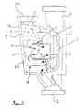
- the centrifugal pump shown in Figure 1 in particular for the Water circuit of a heating system has a pump housing 1 on, with a suction port 2 and one arranged coaxially on the opposite side Pressure port 3, between which the pump chamber 4th is arranged.
- An impeller 5 is located in the pump chamber 4 rotatably supported by a not shown Electric motor is driven on the pump housing is flanged.
- a coaxial impeller inlet 6 is arranged, which consists of a short pipe socket 12.
- This Pipe socket 12 extends into a gas separation chamber 7, the on the opposite side of the electric motor Pump housing 1 is flanged to rotate.
- the pipe socket 12 ends at a distance from the opposite Housing wall 20 of the gas separation chamber 7, which is approximately the half radius of the pipe socket 12 corresponds.
- the pipe socket 12 is smaller as a sieve with a large number Openings 13 executed that have an average diameter of 1 millimeter.
- a housing 9 forms the gas separation chamber 7, which on the has a gas outlet opening 10 at the top which is connected to a vent valve.
- the gas separation chamber 7 is via an annular connection opening 8 with the pump housing 1 or with the suction port 2 connected.
- the connection opening 8 surrounds the pipe socket 12 coaxial and forms the inlet of the chamber 7.
- the outlet of the chamber 7 is formed by the pipe socket 12.
- the suctioned by the pump flows Liquid at a slower speed through the Opening 8 and through the chamber 7 as within the Pipes of the water circuit and nozzles 2 and 3.
- FIG 2 is a preferred embodiment of the pipe socket 12, in which the tube wall in two tube layers 14 and 15 is formed. Between the outer tube layer 14 and the inner pipe layer 15 arranged coaxially thereto a radial distance A is provided so that the funded Liquid also between the two pipe layers 14 and 15 can flow.
- the openings 13a have the outer Pipe layer 14 has a larger diameter than the openings 13i of the inner tube layer 15.
- a guide element 18 as a deflecting means for deflecting the liquid arranged in the centrifugal pump shown in Figures 3 and 4 between the suction nozzle 2 as the liquid inlet Gas separation chamber 7 and the pipe socket 12 .
- the guide element 18 has a semicircular shape Cross section and is at least approximately coaxial to Pipe socket 12 arranged.
- the upper edges 19 of the Guide element 18 are located at least approximately on Height of the axis of the pipe socket 12 and the impeller 5.
- the guide element 18 extends from the free end of the pipe socket 12 opposite chamber wall 20 from in the gas separation chamber 7 into it. This leaves between the free end of the guide element 18 and the chamber wall 21, from which the pipe socket 12 extends, a gap 22, through which a part of the conveyed liquid passes is sucked.
- the remaining part of the liquid is in the channels 24 on both sides between the guide element 18 and the Housing wall 9 led upwards. Above the top edges 19, the partial liquid flows in the direction of Pipe socket 12 deflected. Kick with every turn more gas bubbles from the liquid and rise up to the gas outlet opening 10 or to the one there provided vent valve.
- the surfaces of the guide element 18 have a surface roughness with a multitude of small protrusions and Recesses carried out. This connects the smallest Gas bubbles that get stuck in the rough surface together to form larger gas bubbles that are lighter rise and can thus be eliminated better.
- Pump according to the invention is the tube 12 through a lower one continuously closed tube region 25 is formed on the an upper one with a plurality of small openings 13 provided grating element 26 is arranged.
- the lower Tube section 25 has the shape of a in cross section Semicircle on which is formed by a wire mesh Grid element 26 non-positively placed on it is attached.
- the grid element 26 consists essentially of two in at an angle of approximately 100 ° to each other Grid surfaces 27, the free ends of which are tabs 30 are bent inside and the top edges of the bottom Include pipe area 25 outside.
- the one between the two straight lattice surfaces 27 located edge 28 is oblique is bent inwards such that the chamber wall 21st the pump chamber 4 facing end of the edge 28 inwards is offset towards the axis of the impeller 5.
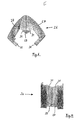
- Figures 6 and 7 is a through a wire mesh formed grid element 26 from different views shown, which is similar to that of Figure 5.
- top contour is the shape of the top Area of the chamber wall 21 formed accordingly on the it is present.
- FIG. 5 can of course also be used a grid element 26 also with the embodiment Figure 3 or 4 can be combined with a guide element 18.
Landscapes
- Engineering & Computer Science (AREA)
- Life Sciences & Earth Sciences (AREA)
- Sustainable Development (AREA)
- Mechanical Engineering (AREA)
- General Engineering & Computer Science (AREA)
- Structures Of Non-Positive Displacement Pumps (AREA)
Abstract
Description
- Figur 1:
- Teilweise aufgeschnittenen Ansicht einer erfindungsgemäßen Pumpe,
- Figur 2:
- Vergrößerte Darstellung einer bevorzugten Ausbildung des Rohres,
- Figur 3:
- Teilweise aufgeschnittene Ansicht einer bevorzugten Pumpe,
- Figur 4:
- Querschnitt durch die Pumpe aus Figur 3
- Figur 5:
- Dreidimensionale Ansicht einer aufgeschnittenen Gasabscheidekammer einer Ausführungsvariante
- Figur 6:
- Gitterelement der Variante aus Figur 5 aus einer ersten Richtung, und
- Figur 7:
- Gitterelement der Variante aus Figur 5 aus einer anderen Richtung.
Claims (16)
- Kreiselpumpe, mit einer eingangsseitig angeordneten Gasabscheidekammer zum Abscheiden von in der geförderten Flüssigkeit enthaltenem Gas, insbesondere Luft, über einen oben an der Gasabscheidekammer angeordneten Gasauslaß, wobei der Flüssigkeitsauslaß der Gasabscheidekammer ein zur Laufradmitte führendes Rohr ist, das in die Gasabscheidekammer hineinreicht und in einem Abstand von der dem freien Rohrende gegenüberliegenden Kammerwand endet,
dadurch gekennzeichnet,
daß das Rohr (12) mit einer Vielzahl von Öffnungen (13) ausgeführt ist. - Pumpe nach Anspruch 1, dadurch gekennzeichnet, daß das Rohr (12) von einem Gitter, Geflecht oder siebförmigen Material oder von einem Filter oder porigen Material gebildet ist.
- Pumpe nach Anspruch 1 oder 2, dadurch gekennzeichnet, daß das Rohr (12) mehrlagig, insbesondere zweilagig ausgeführt ist.
- Pumpe nach Anspruch 3, dadurch gekennzeichnet, daß zwischen den einzelnen Rohrlagen (14, 15) ein Abstand (A) vorgesehen ist.
- Pumpe nach Anspruch 3 oder 4, dadurch gekennzeichnet, daß die Öffnungen (13a) einer äußeren Rohrlage (14) größer sind, als die Öffnungen (13i) einer inneren Rohrlage (15).
- Pumpe nach einem der vorherigen Ansprüche, dadurch gekennzeichnet, daß zwischen dem Flüssigkeitseinlaß der Gasabscheidekammer und dem Rohr (12) Umlenkmittel (18) zum Umlenken der Flüssigkeit angeordnet sind, die sich zumindest für einen Teil der Flüssigkeit in dem direkten Weg zwischen dem Flüssigkeitseinlaß und dem Rohr (12) befinden.
- Pumpe nach Anspruch 6, dadurch gekennzeichnet, daß die Umlenkmittel (18) die Flüssigkeit zu einer oder mehreren Kammerwänden (20, 21) umlenken.
- Pumpe nach Anspruch 6 oder 7, dadurch gekennzeichnet, daß die Umlenkmittel (18) sich von der dem freien Rohrende gegenüberliegenden Kammerwand (20) aus in die Gasabscheidekammer (7) hinein erstrecken.
- Pumpe nach einem der Ansprüche 6 bis 8, dadurch gekennzeichnet, daß die Umlenkmittel (18) einen kreisabschnittförmigen Querschnitt aufweisen und in einem radialen Abstand konzentrisch zum Rohr (12) angeordnet sind.
- Pumpe nach einem der Ansprüche 6 bis 9, dadurch gekennzeichnet, daß die Umlenkmittel durch ein zusammenhängendes Leitelement (18) gebildet sind.
- Pumpe nach einem der Ansprüche 6 bis 10, dadurch gekennzeichnet, daß die Umlenkmittel (18) eine Vielzahl von Öffnungen aufweisen.
- Pumpe nach einem der vorherigen Ansprüche, dadurch gekennzeichnet, daß die Oberflächen der Umlenkmittel (18) und/oder der innenseitigen Kammerwände (20, 21) der Gasabscheidekammer (7) eine Rauhigkeit mit kleinen Vorsprüngen und/oder Vertiefungen aufweisen.
- Pumpe nach einem der vorherigen Ansprüche, dadurch gekennzeichnet, daß das Rohr (12) durch einen unteren durchgehend geschlossenen oder mit Öffnungen versehenen Rohrbereich (25) gebildet ist, auf dem ein oberes, mit einer Vielzahl von Öffnungen versehenes Gitterelement (26), insbesondere ein Sieb oder Drahtgeflecht angeordnet ist.
- Pumpe nach Anspruch 13, dadurch gekennzeichnet, daß der untere Rohrbereich kreisabschnittförmig ausgebildet ist und das Gitterelement (26) im wesentlichen zwei in einem Winkel zueinander angeordneten gerade Gitterflächen (27) aufweist.
- Pumpe nach Anspruch 14, dadurch gekennzeichnet, daß die zwischen den beiden geraden Gitterflächen (27) befindliche Kante (28) schräg nach innen geknickt ist, wobei das der Kammerwand (21) der Pumpenkammer (4) zugewandte Ende der Kante (28) in Richtung zur Laufradachse nach innen hin versetzt ist.
- Pumpe nach einem der Ansprüche 13 bis 15, dadurch gekennzeichnet, daß das Gitterelement (26) form- und/oder kraftschlüssig an dem unteren Rohrbereich (25) gehalten ist.
Applications Claiming Priority (4)
| Application Number | Priority Date | Filing Date | Title |
|---|---|---|---|
| DE19903047 | 1999-01-26 | ||
| DE19903047 | 1999-01-26 | ||
| DE19920780A DE19920780A1 (de) | 1999-01-26 | 1999-05-05 | Kreiselpumpe mit Gasabscheidekammer |
| DE19920780 | 1999-05-05 |
Publications (3)
| Publication Number | Publication Date |
|---|---|
| EP1024292A2 true EP1024292A2 (de) | 2000-08-02 |
| EP1024292A3 EP1024292A3 (de) | 2001-08-16 |
| EP1024292B1 EP1024292B1 (de) | 2004-08-04 |
Family
ID=26051495
Family Applications (1)
| Application Number | Title | Priority Date | Filing Date |
|---|---|---|---|
| EP00100942A Expired - Lifetime EP1024292B1 (de) | 1999-01-26 | 2000-01-19 | Kreiselpumpe mit Gasabscheidekammer |
Country Status (1)
| Country | Link |
|---|---|
| EP (1) | EP1024292B1 (de) |
Cited By (6)
| Publication number | Priority date | Publication date | Assignee | Title |
|---|---|---|---|---|
| EP1873399A1 (de) * | 2006-06-29 | 2008-01-02 | Grundfos Management A/S | Kreiselpumpenaggregat |
| EP2420609A3 (de) * | 2010-08-20 | 2017-08-30 | BSH Hausgeräte GmbH | Laugenpumpe für wasserführende Haushaltgeräte und wasserführendes Haushaltgerät |
| DE102021201337A1 (de) | 2020-02-17 | 2021-08-19 | Lg Electronics Inc. | Pumpe |
| KR20210109796A (ko) * | 2020-02-28 | 2021-09-07 | 엘지전자 주식회사 | 유체 순환 펌프용 가스 분리구 |
| KR20210110060A (ko) * | 2020-02-28 | 2021-09-07 | 엘지전자 주식회사 | 펌프 |
| CN119367820A (zh) * | 2024-12-27 | 2025-01-28 | 浙江乾辰智能科技有限公司 | 一种自吸式多级离心泵用排气分离机构 |
Citations (1)
| Publication number | Priority date | Publication date | Assignee | Title |
|---|---|---|---|---|
| DE3109918C2 (de) | 1981-03-14 | 1989-03-16 | Wilo-Werk Gmbh & Co Pumpen- Und Apparatebau, 4600 Dortmund | Flüssigkeitspumpe mit Gasabscheidekammer |
Family Cites Families (7)
| Publication number | Priority date | Publication date | Assignee | Title |
|---|---|---|---|---|
| US2370778A (en) * | 1943-05-24 | 1945-03-06 | Pesco Products Co | Booster pump |
| DE1653725A1 (de) * | 1967-09-29 | 1972-01-13 | Hanning Elektro Werke | Umwaelzpumpe fuer Heizungsanlagen |
| DE1937119A1 (de) * | 1969-07-22 | 1971-02-04 | Loewe Pumpenfabrik Gmbh | Zentrifugalpumpe mit Gasabscheidung |
| DE3637040A1 (de) * | 1986-10-31 | 1988-05-19 | Grundfos Int | Kreiselpumpe als umwaelzpumpe fuer heizungsanlagen |
| DE3724684A1 (de) * | 1987-07-25 | 1989-02-02 | Oplaender Wilo Werk Gmbh | Vorrichtung zum abscheiden von luft |
| DE3813654A1 (de) * | 1988-04-22 | 1989-11-02 | Licentia Gmbh | Umwaelzpumpe |
| DE29718285U1 (de) * | 1997-10-15 | 1997-12-11 | Grundfos A/S, Bjerringbro | Umwälzkreiselpumpe mit Entlüftungseinrichtung |
-
2000
- 2000-01-19 EP EP00100942A patent/EP1024292B1/de not_active Expired - Lifetime
Patent Citations (1)
| Publication number | Priority date | Publication date | Assignee | Title |
|---|---|---|---|---|
| DE3109918C2 (de) | 1981-03-14 | 1989-03-16 | Wilo-Werk Gmbh & Co Pumpen- Und Apparatebau, 4600 Dortmund | Flüssigkeitspumpe mit Gasabscheidekammer |
Cited By (12)
| Publication number | Priority date | Publication date | Assignee | Title |
|---|---|---|---|---|
| EP1873399A1 (de) * | 2006-06-29 | 2008-01-02 | Grundfos Management A/S | Kreiselpumpenaggregat |
| CN101096954B (zh) * | 2006-06-29 | 2011-09-14 | 格伦德福斯管理联合股份公司 | 离心泵装置 |
| US9028204B2 (en) | 2006-06-29 | 2015-05-12 | Grundfos Management A/S | Centrifugal pump assembly |
| EP2420609A3 (de) * | 2010-08-20 | 2017-08-30 | BSH Hausgeräte GmbH | Laugenpumpe für wasserführende Haushaltgeräte und wasserführendes Haushaltgerät |
| DE102021201337A1 (de) | 2020-02-17 | 2021-08-19 | Lg Electronics Inc. | Pumpe |
| US11661953B2 (en) | 2020-02-17 | 2023-05-30 | Lg Electronics Inc. | Pump |
| KR20210109796A (ko) * | 2020-02-28 | 2021-09-07 | 엘지전자 주식회사 | 유체 순환 펌프용 가스 분리구 |
| KR20210110060A (ko) * | 2020-02-28 | 2021-09-07 | 엘지전자 주식회사 | 펌프 |
| KR102798841B1 (ko) | 2020-02-28 | 2025-04-22 | 엘지전자 주식회사 | 유체 순환 펌프용 가스 분리구 |
| KR102828707B1 (ko) | 2020-02-28 | 2025-07-03 | 엘지전자 주식회사 | 펌프 |
| US12366254B2 (en) | 2020-02-28 | 2025-07-22 | Lg Electronics Inc. | Pump with suction chamber impact body |
| CN119367820A (zh) * | 2024-12-27 | 2025-01-28 | 浙江乾辰智能科技有限公司 | 一种自吸式多级离心泵用排气分离机构 |
Also Published As
| Publication number | Publication date |
|---|---|
| EP1024292A3 (de) | 2001-08-16 |
| EP1024292B1 (de) | 2004-08-04 |
Similar Documents
| Publication | Publication Date | Title |
|---|---|---|
| EP3525905B1 (de) | Filtervorrichtung | |
| DE102005031420B4 (de) | Kombinierte Tauch-/Flachabsaug-Rotationspumpe mit konzentrischer Laufradeintrittsöffnung | |
| DE102015107721A1 (de) | Ölgeschmierte Drehschieber-Vakuumpumpe | |
| EP0132801A2 (de) | Durchströmturbine | |
| CH625713A5 (de) | ||
| EP0416146B1 (de) | Vorrichtung zum Abtrennen von Feststoffteilchen und Fluiden höherer Dichte von Fluiden niederer Dichte | |
| DE202016008410U1 (de) | Filtereinrichtung | |
| DE102008044505B4 (de) | Radialverdichter | |
| EP1024292B1 (de) | Kreiselpumpe mit Gasabscheidekammer | |
| DE3109918C2 (de) | Flüssigkeitspumpe mit Gasabscheidekammer | |
| EP2433692A1 (de) | Vorrichtung zum Entfernen von Siebgut aus in einem Gerinne strömender Flüssigkeit | |
| EP1685784B1 (de) | Sauggerät | |
| EP2362101B1 (de) | Dosierpumpe | |
| DE1571759B2 (de) | Gaswaescher | |
| EP3519699B1 (de) | Pumpenanordnung | |
| DE2159963B2 (de) | Kavitationsmindernde Drosselvorrichtung | |
| DE69119765T2 (de) | Pumpe mit spiralförmigen schaufeln | |
| DE10393196T5 (de) | Zentrifugalabscheider | |
| DE19920780A1 (de) | Kreiselpumpe mit Gasabscheidekammer | |
| DE3537906A1 (de) | Zyklon-abscheider | |
| DE2157444C3 (de) | Dynamische Trennvorrichtung zum Abtrennen von in verunreinigten Flüssigkeiten suspendierten Teilchen | |
| DE3438480A1 (de) | Mehrstufige kreiselpumpe mit geschlossenem laufradgehaeuse | |
| DE8526836U1 (de) | Einrichtung zum Auffangen von Reinigungskörpern aus einem Kühlwasserstrom | |
| DE60303788T2 (de) | Selbstansaugende Kreiselpumpe | |
| EP0667455B1 (de) | Doppelpumpe |
Legal Events
| Date | Code | Title | Description |
|---|---|---|---|
| PUAI | Public reference made under article 153(3) epc to a published international application that has entered the european phase |
Free format text: ORIGINAL CODE: 0009012 |
|
| AK | Designated contracting states |
Kind code of ref document: A2 Designated state(s): DE FR GB IT |
|
| AX | Request for extension of the european patent |
Free format text: AL;LT;LV;MK;RO;SI |
|
| PUAL | Search report despatched |
Free format text: ORIGINAL CODE: 0009013 |
|
| AK | Designated contracting states |
Kind code of ref document: A3 Designated state(s): AT BE CH CY DE DK ES FI FR GB GR IE IT LI LU MC NL PT SE |
|
| AX | Request for extension of the european patent |
Free format text: AL;LT;LV;MK;RO;SI |
|
| 17P | Request for examination filed |
Effective date: 20011114 |
|
| AKX | Designation fees paid |
Free format text: DE FR GB IT |
|
| 17Q | First examination report despatched |
Effective date: 20030314 |
|
| GRAP | Despatch of communication of intention to grant a patent |
Free format text: ORIGINAL CODE: EPIDOSNIGR1 |
|
| GRAS | Grant fee paid |
Free format text: ORIGINAL CODE: EPIDOSNIGR3 |
|
| RAP1 | Party data changed (applicant data changed or rights of an application transferred) |
Owner name: WILO AG |
|
| GRAA | (expected) grant |
Free format text: ORIGINAL CODE: 0009210 |
|
| AK | Designated contracting states |
Kind code of ref document: B1 Designated state(s): DE FR GB IT |
|
| REG | Reference to a national code |
Ref country code: GB Ref legal event code: FG4D Free format text: NOT ENGLISH |
|
| REF | Corresponds to: |
Ref document number: 50007235 Country of ref document: DE Date of ref document: 20040909 Kind code of ref document: P |
|
| GBT | Gb: translation of ep patent filed (gb section 77(6)(a)/1977) | ||
| PLBE | No opposition filed within time limit |
Free format text: ORIGINAL CODE: 0009261 |
|
| STAA | Information on the status of an ep patent application or granted ep patent |
Free format text: STATUS: NO OPPOSITION FILED WITHIN TIME LIMIT |
|
| ET | Fr: translation filed | ||
| 26N | No opposition filed |
Effective date: 20050506 |
|
| PGFP | Annual fee paid to national office [announced via postgrant information from national office to epo] |
Ref country code: GB Payment date: 20150114 Year of fee payment: 16 |
|
| REG | Reference to a national code |
Ref country code: FR Ref legal event code: PLFP Year of fee payment: 17 |
|
| GBPC | Gb: european patent ceased through non-payment of renewal fee |
Effective date: 20160119 |
|
| PG25 | Lapsed in a contracting state [announced via postgrant information from national office to epo] |
Ref country code: GB Free format text: LAPSE BECAUSE OF NON-PAYMENT OF DUE FEES Effective date: 20160119 |
|
| REG | Reference to a national code |
Ref country code: FR Ref legal event code: PLFP Year of fee payment: 18 |
|
| PGFP | Annual fee paid to national office [announced via postgrant information from national office to epo] |
Ref country code: FR Payment date: 20161221 Year of fee payment: 18 |
|
| PGFP | Annual fee paid to national office [announced via postgrant information from national office to epo] |
Ref country code: DE Payment date: 20161219 Year of fee payment: 18 |
|
| PGFP | Annual fee paid to national office [announced via postgrant information from national office to epo] |
Ref country code: IT Payment date: 20170103 Year of fee payment: 18 |
|
| REG | Reference to a national code |
Ref country code: DE Ref legal event code: R119 Ref document number: 50007235 Country of ref document: DE |
|
| PG25 | Lapsed in a contracting state [announced via postgrant information from national office to epo] |
Ref country code: DE Free format text: LAPSE BECAUSE OF NON-PAYMENT OF DUE FEES Effective date: 20180801 Ref country code: FR Free format text: LAPSE BECAUSE OF NON-PAYMENT OF DUE FEES Effective date: 20180131 |
|
| REG | Reference to a national code |
Ref country code: FR Ref legal event code: ST Effective date: 20180928 |
|
| PG25 | Lapsed in a contracting state [announced via postgrant information from national office to epo] |
Ref country code: IT Free format text: LAPSE BECAUSE OF NON-PAYMENT OF DUE FEES Effective date: 20180119 |