EP1024276B1 - Internal combustion piston engine - Google Patents
Internal combustion piston engine Download PDFInfo
- Publication number
- EP1024276B1 EP1024276B1 EP99123317A EP99123317A EP1024276B1 EP 1024276 B1 EP1024276 B1 EP 1024276B1 EP 99123317 A EP99123317 A EP 99123317A EP 99123317 A EP99123317 A EP 99123317A EP 1024276 B1 EP1024276 B1 EP 1024276B1
- Authority
- EP
- European Patent Office
- Prior art keywords
- crankshaft
- lanchester
- bearing
- shaft
- accordance
- Prior art date
- Legal status (The legal status is an assumption and is not a legal conclusion. Google has not performed a legal analysis and makes no representation as to the accuracy of the status listed.)
- Expired - Lifetime
Links
Images


Classifications
-
- F—MECHANICAL ENGINEERING; LIGHTING; HEATING; WEAPONS; BLASTING
- F02—COMBUSTION ENGINES; HOT-GAS OR COMBUSTION-PRODUCT ENGINE PLANTS
- F02F—CYLINDERS, PISTONS OR CASINGS, FOR COMBUSTION ENGINES; ARRANGEMENTS OF SEALINGS IN COMBUSTION ENGINES
- F02F7/00—Casings, e.g. crankcases or frames
- F02F7/0002—Cylinder arrangements
- F02F7/0007—Crankcases of engines with cylinders in line
-
- F—MECHANICAL ENGINEERING; LIGHTING; HEATING; WEAPONS; BLASTING
- F16—ENGINEERING ELEMENTS AND UNITS; GENERAL MEASURES FOR PRODUCING AND MAINTAINING EFFECTIVE FUNCTIONING OF MACHINES OR INSTALLATIONS; THERMAL INSULATION IN GENERAL
- F16F—SPRINGS; SHOCK-ABSORBERS; MEANS FOR DAMPING VIBRATION
- F16F15/00—Suppression of vibrations in systems; Means or arrangements for avoiding or reducing out-of-balance forces, e.g. due to motion
- F16F15/22—Compensation of inertia forces
- F16F15/26—Compensation of inertia forces of crankshaft systems using solid masses, other than the ordinary pistons, moving with the system, i.e. masses connected through a kinematic mechanism or gear system
- F16F15/264—Rotating balancer shafts
- F16F15/265—Arrangement of two or more balancer shafts
Definitions
- the individual bearings 25 to 29 are thus each by one Bearing shell 7 and by a respective bearing base 13 for Recording the crankshaft 5 is formed.
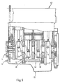
- FIG. 5 a four-cylinder engine is shown in section. From this drawing it can be seen that the crankshaft 5 and the five consecutive bearings 25 to 29 via tie bolts 23 (see FIG. 2) are detachably connected to a cylinder head 47 and in this embodiment, only the second and fourth bearing base 13 with the bearing upper part 12 and 12 'form a one-piece component 44. Further, according to this example, the shaft 43 may have the Lanchester compensation, while the first shaft 42 may be formed as a smooth shaft without mass balance.
- the drive wheel 14 as a sprocket is formed and a traction means 19 with one of Drive wheels of the shaft 42 is in drive connection.
Landscapes
- Engineering & Computer Science (AREA)
- General Engineering & Computer Science (AREA)
- Mechanical Engineering (AREA)
- Physics & Mathematics (AREA)
- Acoustics & Sound (AREA)
- Aviation & Aerospace Engineering (AREA)
- Chemical & Material Sciences (AREA)
- Combustion & Propulsion (AREA)
- Shafts, Cranks, Connecting Bars, And Related Bearings (AREA)
- Cylinder Crankcases Of Internal Combustion Engines (AREA)
Description
Die Erfindung bezieht sich auf eine Hubkolben-Brennkraftmaschine mit einer in Lagern aufgenommenen Kurbelwelle, einem Massenausgleich erster Ordnung und einem Lanchesterausgleich, zu dem zwei in Lagern aufgenommene Wellen gehören, die in einem Kurbelgehäuse aufgenommen sind.The invention relates to a reciprocating internal combustion engine with a recorded in camps Crankshaft, a first-order mass balancing and a Lanchester compensation, to which two recorded in camps waves belong, which are housed in a crankcase.
Die Druckschrift 1 (DE 38 24 553 C1) zeigt eine Hubkolben-Brennkraftmaschine mit einem Kurbelwellenlager und einem Massenausgleich (Lanchester) zweiter Ordnung, die in einem Kurbelgehäuse aufgenommen sind, wobei zumindest ein Lagerunterteil des Lagers der Kurbelwelle mit mindestens einem Lager der Lanchester-Welle verbunden ist. Das Lager ist hierzu an der Unterseite der Lagerbrücke angeformt. Das Lageroberteil der Ausgleichswellen zweiter Ordnung ist mit der Lagerbrücke und nicht einteilig mit dem Lagerunterteil verbunden. Gemäß Figur 5 ist keine Trennebene der Ausgleichslagerschalen und keine Verschraubung der Ausgleichslager offenbart. Zumindest die Trennebene wäre aber notwendig, um die Montage der Ausgleichswellen zu realisieren. Demnach ist aus dieser Druckschrift das erfindungsgemäße Lager bzw. die einteilige Ausbildung von Lagerunterteil der Kurbelwelle und Lageroberteil der Lanchester-Welle nicht zu entnehmen.The document 1 (DE 38 24 553 C1) shows a reciprocating internal combustion engine with a crankshaft bearing and a Mass balance (Lanchester) second order, which in one Crankcase are received, wherein at least one Bearing base of the bearing of the crankshaft with at least one Stock of the Lanchester shaft is connected. The camp is for this molded on the underside of the bearing bridge. The bearing shell the balance shafts second order is with the bearing bridge and not integrally connected to the bearing base. According to Figure 5 is not a parting plane of the balance bearing shells and no screw connection of the balance bearing disclosed. At least But the dividing plane would be necessary for the assembly of the Balance shafts to realize. Accordingly, from this Document the bearing of the invention or the one-piece Training of bearing base of the crankshaft and Bearing upper part of the Lanchester shaft can not be seen.
Die Druckschrift 2 (DE 41 34 399 A1)zeigt auch eine
Hubkolben-Brennkraftmaschine für ein Kraftfahrzeug, die eine
in Lagern aufgenommene Kurbelwelle und einen Massenausgleich
erster Ordnung sowie einen Massenausgleich zweiter Ordnung
zeigt, zu der mehrere in Lagern aufgenommene Wellen gehören,
die in einem Kurbelwellengehäuse aufgenommen sind. Das
Lagergehäuse des Massenausgleichs zweiter Ordnung (Lanchester-Ausgleich)
ist über eine Flanschverbindung lösbar mit dem
Kurbelgehäuse der Kurbelwelle verbunden. Die getrennte
Bauweise des untergehängten Lanchester-Gehäuses führt zu einem
erheblichen Arbeitsaufwand bei der Herstellung der Lager der
Kurbelwelle und der Lager des Lanchester-Massenausgleichs,
insbesondere deshalb, weil für die Bearbeitung der Lager ein
sehr häufiges Umspannen der einzelnen Bauteile erforderlich
ist. Ein erheblicher Arbeitsaufwand zur Bearbeitung der Lager
ist auch erforderlich, um ein exaktes Stichmaß zwischen den
Lagern der Kurbelwelle und den Lagern des Lanchesters zu
erreichen.The document 2 (
Aus der Druckschrift 3 (US 4,926,810) ist eine Hubkolben-Brennkraftmaschine mit einer in Lagern aufgenommenen Kurbelwelle bekannt, die einen desmodromischen Massenausgleich aufweist. Der Massenausgleich besteht aus Massenausgleichsgewichten, die jeweils mit einem Kurbelwellenlager verbunden sind.From document 3 (US 4,926,810) is a reciprocating internal combustion engine with a recorded in camps Crankshaft known that a desmodromic mass balance having. The mass balance consists of Mass balance weights, each with a Crankshaft bearings are connected.
Der Erfindung liegt die Aufgabe zugrunde, den Lagerdeckel bzw. das Lageroberteil des Massenausgleichs zweiter Ordnung in das Lager der Kurbelwelle zu integrieren.The invention is based on the object, the bearing cap or the upper part of the mass balance second order in the To integrate bearings of the crankshaft.
Gelöst wird die Aufgabe erfindungsgemäß dadurch, daß zumindest ein Lagerunterteil des Lagers der Kurbelwelle mit mindestens einem Lager der Lanchester-Welle zu einem einteiligen Bauteil verbunden ist, wobei das einteilige Bauteil einerseits an ein Lageroberteil der Kurbelwelle, andererseits an ein Lagerunterteil der Lanchester-Welle angeschlossen ist. Hierdurch wird erreicht, daß der Bearbeitungsaufwand der nun vermiedenen Trennfläche sowie die damit verbundenen Toleranzprobleme entfallen. Die Bearbeitung der Lager, der Kurbelwelle und der Lanchester-Welle sind auf einfache Weise möglich, ohne daß die Werkstücke mehrmals umgespannt werden müssen. Das führt auch dazu, daß das Stichmaß zwischen den Lagern der Kurbelwelle und den Lagern der Lanchester-Wellen exakt eingehalten werden kann und auf diese Weise das Zahnflankenspiel auf ein Minimum reduziert werden kann. Hierdurch werden die Laufgeräusche des Motors ebenfalls erheblich verringert. Durch die einteilige Bauweise von Lagerunterteil der Kurbelwelle und Lageroberteil der Lanchester-Welle wird neben der Bearbeitungszeit auch die Zeit zur Montage der einzelnen Wellen sowie das Zahnflankenspiel und somit der Einstellungsaufwand erheblich reduziert. Sollte eine nachträgliche Justierung der Lager erforderlich sein, so läßt sich dies durch die Verwendung unterschiedlich dimensionierter Lagerschalen bewerkstelligen. Die Lanchester-Welle läßt sich darüber hinaus in ihrem Längsaufbau und bezüglich der entsprechenden Durchmesser so optimieren, daß eine Positionierung der einzelnen Wellen bei Sicherstellung eines höchstmöglichen Freiheitsgrades bewerkstelligt werden kann.The object is achieved according to the invention in that at least a bearing base of the bearing of the crankshaft with at least a bearing of the Lanchester shaft to a one-piece component is connected, wherein the one-piece component on the one hand to a Bearing upper part of the crankshaft, on the other hand to a Lower part of the Lanchester shaft is connected. This ensures that the processing cost of now avoided separating surface as well as the associated Tolerance problems are eliminated. The processing of the bearings, the Crankshaft and the Lanchester shaft are simple possible, without the workpieces are re-clamped several times have to. This also causes the gauge between the Bearing the crankshaft and the bearings of the Lanchester waves can be maintained exactly and in this way the Backlash can be reduced to a minimum. As a result, the running noise of the engine are also significantly reduced. Due to the one-piece construction of Bearing base of the crankshaft and bearing shell of the Lanchester wave is next to the processing time and the time for mounting the individual shafts and the backlash and thus considerably reduces the setting effort. Should a subsequent adjustment of the bearings may be required, so This can be different by the use accomplish dimensioned bearing shells. The Lanchester wave can be in addition in their longitudinal structure and optimize with respect to the corresponding diameter so that a positioning of the individual waves when ensuring of the highest possible degree of freedom can.
Ferner ist es vorteilhaft, daß das einteilige Bauteil der Kurbelwelle neben den beiden Lageroberteilen für die beiden Lanchester-Wellen ein weiteres Lagerunterteil für eine dritte Welle des Lanchesters aufweist. Durch die einteilige Bauweise des Lagerunterteils der Kurbelwelle in Verbindung mit dem Lageroberteil der Lanchester-Wellen ist es ebenfalls möglich, in diesem Teil ein weiteres Lagerelement für eine dritte Welle zu integrieren, wodurch sich ebenfalls die Herstellungskosten und Montagezeiten wesentlich reduzieren und sich das Flankenspiel verringern läßt.Furthermore, it is advantageous that the one-piece component of Crankshaft next to the two upper bearing parts for the two Lanchester waves another bearing base for a third Has wave of Lanchester. Due to the one-piece construction the bearing base of the crankshaft in conjunction with the Bearing top of the Lanchester waves, it is also possible in this part, another bearing element for a third wave to integrate, which also reduces the cost of production and significantly reduce assembly times and the Reduce backlash.
Eine zusätzliche Möglichkeit ist gemäß einer Weiterbildung der erfindungsgemäßen Vorrichtung, daß das Lagerunterteil der Kurbelwelle und die beiden Lageroberteile der nebeneinander liegenden Lanchester Wellen sowie das Lagerunterteil für die dritte Welle des Lanchesters einteilig miteinander verbunden sind bzw. eine Baueinheit bzw. ein Bauteil bilden.An additional possibility is according to a development of Device according to the invention that the lower part of the bearing Crankshaft and the two bearing shells side by side lying Lanchester waves and the bearing base for the third wave of the Lanchester integrally connected are or form a structural unit or a component.
Gemäß einer bevorzugten Ausführungsform der erfindungsgemäßen Lösung ist schließlich vorgesehen, daß das einteilige Bauteil über Verbindungselemente mit dem Lageroberteil der Kurbelwelle und/oder mit Teilen des Kurbelgehäuses lösbar verbunden ist.According to a preferred embodiment of the invention Solution is finally provided that the one-piece component via connecting elements with the bearing upper part of the crankshaft and / or releasably connected to parts of the crankcase.
Von besonderer Bedeutung ist für die vorliegende Erfindung, daß das einteilige Bauteil über Zugankerschrauben mit dem Lageroberteil der Kurbelwelle und/oder dem Zylinderkopf verbunden ist und über Zugankerschrauben mit dem Lageroberteil der Kurbelwelle und zusätzlich über Querverschraubungselemente mit dem Kurbelgehäuse bzw. mit einem Lagerstuhl verbunden ist. Hierdurch wird eine sehr exakte und einwandfreie Integrierung von Lagerunterteil der Kurbelwelle und Lageroberteil der Lanchester-Wellen im Kurbelgehäuse sichergestellt und eine sitzende Befestigung geschaffen.Of particular importance for the present invention, that the one-piece component via tie bolts with the Bearing top of the crankshaft and / or the cylinder head is connected and via tie bolts with the bearing shell the crankshaft and in addition cross-bolting is connected to the crankcase or with a bearing block. This is a very accurate and perfect integration from bearing base of the crankshaft and bearing shell of the Lanchester shafts secured in the crankcase and one seated attachment created.
Vorteilhaft ist es ferner, daß auf der Kurbelwelle ein Abtriebsrad vorgesehen ist, das über ein erstes Antriebsrad mit der ersten Lanchester-Welle antriebsverbunden ist, das wiederum mit einem zweiten Antriebsrad der zweiten Lanchester-Welle in Antriebsverbindung steht. It is also advantageous that on the crankshaft Output gear is provided, which has a first drive wheel is drivingly connected to the first Lanchester wave, the in turn with a second drive wheel of the second Lanchester shaft is in drive connection.
Außerdem ist es vorteilhaft, daß das auf der Kurbelwelle angeordnete Abtriebsrad über das erste Antriebsrad mit der ersten Lanchester-Welle und mit einem dritten Antriebsrad der dritten Lanchester-Welle in Antriebsverbindung steht. Hierdurch wird auch gewährleistet, daß die Wellen der Lanchester-Anordnung möglichst nahe in dem Bereich der Kurbelwellen plaziert werden, so daß hier auch der Platzbedarf der einzelnen Wellen im Kurbelgehäuse klein gehalten werden kann.In addition, it is advantageous that on the crankshaft arranged output gear via the first drive wheel with the first Lanchester shaft and with a third drive wheel the third Lanchester shaft is drivingly connected. This will also ensure that the waves of Lanchester arrangement as close as possible in the area of Crankshafts are placed so that here also the space the individual shafts are kept small in the crankcase can.
Vorteilhaft ist es ferner, daß die Lager bzw. die Lagerschalen der Kurbelwelle und/oder Lager bzw. die Lagerschalen der Lanchester-Wellen aus dem gleichen oder annähernd gleichen Werkstoff mit gleichem oder ahnähernd gleichem Wärmeausdehnungskoeffizient wie die Kurbelwelle bestehen.It is also advantageous that the bearings or the bearing shells the crankshaft and / or bearings or the bearing shells of Lanchester waves from the same or approximately the same Material with the same or approximately the same Thermal expansion coefficient as the crankshaft exist.
Weitere Vorteile und Einzelheiten der Erfindung sind in den Patentansprüchen und in der Beschreibung erläutert und in den Figuren dargestellt.Further advantages and details of the invention are in the Claims and explained in the description and in the Figures shown.
Es zeigt:
Figur 1- einen Querschnitt durch eine Hubkolben-Brennkraftmaschine mit einer in Lagern aufgenommenen Kurbelwelle und einem Lanchesterausgleich,
- Figur 2
- ein zweites Ausführungsbeispiel der Hubkolben-Brennkraftmaschine mit Lanchesterausgleich, wobei der Lanchesterausgleich drei Wellen aufweist,
- Figur 3
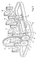
- eine perspektivische Darstellung der einzelnen Lagerunterteile zur Aufnahme der Kurbelwelle mit dem zwei Wellen aufweisenden Lanchesterausgleich,
- Figur 4
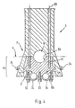
- eine Schnittdarstellung eines Teils des Kurbelgehäuses mit dem einteiligen Lageroberteil und Lagerunterteil,
- Figur 5
- einen Längsschnitt eines Vierzylindermotors mit einem Massenausgleich erster Ordnung und einem Lanchester-Ausgleich (Massenausgleich zweiter Ordnung).
- FIG. 1
- a cross section through a reciprocating internal combustion engine with a recorded in bearings crankshaft and a Lanchester balancing,
- FIG. 2
- a second embodiment of the reciprocating internal combustion engine with Lanchesterausgleich, wherein the Lanchesterausgleich has three waves,
- FIG. 3
- a perspective view of the individual bearing parts for receiving the crankshaft with the two-shaft Lanchesterausgleich,
- FIG. 4
- a sectional view of a portion of the crankcase with the one-piece bearing shell and bearing base,
- FIG. 5
- a longitudinal section of a four-cylinder engine with a first-order mass balance and a Lanchester compensation (second-order mass balance).
In der Zeichnung ist mit 50 eine Hubkolben-Brennkraftmaschine
bezeichnet, die beispielsweise als Viertaktzylindermotor
ausgebildet sein kann und ein Kurbelgehäuse 1 umfaßt, das in
Fig. 1 und 5 einen Zylinderblock 48 zeigt, auf dem ein
Zylinderkopf 47 mittels Zugankerschrauben 23 befestigt ist. In
dem Kurbelgehäuse 1 befindet sich eine Kurbelstange 49, die an
ihrem oberen Ende mit einem Kolben 51 verbunden ist und mit
ihrem anderen Ende an eine Kurbelwelle 5 angeschlossen ist.
In dem Kurbelgehäuse 1 befindet sich ein der Kurbelwelle 5
zugeordneter Massenausgleich 40 erster Ordnung und ein
Lanchesterausgleich 41 (Massenausgleich zweiter Ordnung), die
insbesondere in Fig. 3 veranschaulicht sind.In the drawing, 50 is a reciprocating internal combustion engine
referred to, for example, as a four-stroke cylinder engine
may be formed and comprises a
In Fig. 3 ist die Kurbelwelle 5 weggelassen und nur deren
Lager 25, 26, 27, 28 und 29 dargestellt. Die Lager 25 bis 29
sind über in Fig. 1, 2 dargestellte Schrauben bzw.
Zugankerschrauben 23 mit Lageroberteilen 7 und dem
Zylinderkopf 47 (vgl. Fig. 1) lösbar verbunden.In Fig. 3, the crankshaft 5 is omitted and only their
Die einzelnen Lager 25 bis 29 werden also durch je ein
Lageroberteil 7 und durch je ein Lagerunterteil 13 zur
Aufnahme der Kurbelwelle 5 gebildet.The
Die Lageroberteile 7 bzw. Lagerdeckel können aus einem
ähnlichen Werkstoff mit ähnlichem Wärmeausdehnungskoeffizenten
wie die Kurbelwelle 5 ausgebildet sein. Das Lagerunterteil 13
bzw. der Lagerstuhl der Kurbelwelle 5 kann ebenfalls aus einem
ähnlichen Werkstoff mit gleichem Wärmeausdehnungskoeffizienten
wie die Kurbelwelle 5 gebildet sein. Beispielsweise ist es
möglich, hierfür GGG, Sinter-Alu oder andere Verbundwerkstoffe
zu wählen. Die in Fig. 3 perspektivisch dargestellten
Lagerunterteile 26 und 28 sind einteilig mit einem
Lageroberteil 12 bzw. 12' des Lanchesterausgleichs verbunden.
Das Lagerunterteil 26 bzw. 28 und das Lageroberteil 12, 12'
bilden also eine Baueinheit bzw. ein einteiliges Bauteil 44.
Das aus den Teilen 26 und 12 gebildete Bauteil 44 ist
ebenfalls über die in Fig. 1 bzw. 2 dargestellten
Zugankerschrauben 23 mit dem Zylinderkopf 47 lösbar verbunden.The
Der Lanchesterausgleich 41 weist zwei parallel zueinander
verlaufende Wellen 42 und 43 auf, die in Lagerschalen 34 und
35 drehbar aufgenommen sind, die über die Schrauben 52, 53, 55
mit dem Lagerunterteil 13 lösbar verbunden sind.
Der Antrieb der Lanchester-Wellen 42 und 43 erfolgt gemäß
Fig. 3 über ein Zahnradgetriebe. Hierzu gehört ein auf der
Kurbelwelle 5 angeordnetes Antriebsrad 14, das in Eingriff mit
einem ersten Antriebsrad 17 und einem getriebenen Zahnrad 18
des Lanchesterausgleichs steht. Die Lanchester-Wellen 42 und
43 liegen etwas oberhalb einer Kurbelwanne 16. Das
Antriebsrad 14 ist auf der Kurbelwelle 5 drehfest angeordnet,
während das Antriebsrad 17 auf der Lanchester-Welle 42 und das
getriebene Zahnrad 18 auf der Lanchester-Welle 43 drehfest
vorgesehen ist. Die beiden Lanchester-Wellen 42 und 43
verlaufen parallel zueinander auf einer horizontal
verlaufenden Querebene 8.The
The drive of the
Nach einem weiteren Ausführungsbeispiel gemäß Fig. 2 kann der
Lanchesterausgleich auch aus mindestens drei Wellen 42, 43, 22
bestehen, wobei das Abtriebsrad 14 über ein auf der dritten
Welle 22 angeordnetes Zahnrad 54 direkt antreibt. Die dritte
Welle 22 liegt in etwa auf der gleichen Höhe wie die Lager 25
bis 29 der Kurbelwelle 5, also auf einer horizontalen
Querebene 4.According to a further embodiment of FIG. 2, the
Lanchester compensation also from at least three
Das Antriebsrad 14 steht ferner, wie bereits erwähnt, mit dem
Antriebsrad 17 der Welle 42 in Antriebsverbindung, die
wiederum die Welle 43 über das Antriebsrad 18 antreibt.The
Ein Lagerunterteil 21 der dritten Welle 22 bildet mit den
entsprechenden Lageroberteilen 12 der beiden parallel
zueinander verlaufenden Wellen 42 und 43 ebenfalls ein
einteiliges Bauteil 44, das über die Zugankerschrauben 23
gemäß Fig. 1, 2 mit dem Lageroberteil 7 und auch mit dem
Zylinderkopf 47 lösbar verbunden ist.A bearing
Das einteilige Bauteil 44 der Lanchester-Wellen 42, 43 und 22
kann gemäß Fig. 4 über Querverschraubungselemente 24 mit dem
Unterteil des Kurbelgehäuses 1 zusätzlich lösbar verbunden
werden.The one-
In Fig.5 ist ein Vierzylindermotor im Schnitt dargestellt. Aus
dieser Zeichnung ist ersichtlich, daß die Kurbelwelle 5 und
die fünf hintereinanderliegenden Lager 25 bis 29 über
Zugankerschrauben 23 (vergleiche Fig. 2) mit einem
Zylinderkopf 47 lösbar verbunden sind und bei diesem
Ausführungsbeispiel nur das zweite und
vierte Lagerunterteil 13 mit dem Lageroberteil 12 bzw. 12'
ein einteiliges Bauteil 44 bilden. Ferner kann nach diesem
Beispiel die Welle 43 den Lanchesterausgleich aufweisen,
während die erste Welle 42 als glatte Welle ohne
Massenausgleich ausgebildet sein kann. In Figure 5, a four-cylinder engine is shown in section. From this drawing it can be seen that the crankshaft 5 and the five
Ferner ist es möglich, daß das Antriebsrad 14 als Kettenrad
ausgebildet ist und über ein Zugmittel 19 mit einem der
Antriebsräder der Welle 42 in Antriebsverbindung steht.Further, it is possible that the
Bei der Vierzylinder- Motorversion gemäß Fig. 5 ist das
Lagerunterteil 13 der Kurbelwelle über kurze Schrauben 23'In the four-cylinder engine version of FIG. 5 is the
Die Trennlinie 8 zwischen der Kurbelwanne 16 und dem
Kurbelgehäuse 1 liegt in etwa auf der gleichen horizontalen
Querebene wie die durch die beiden Wellen 42, 43 verlaufende
Querebene bzw. Trennlinie zwischen den Lageroberteilen 12, 12'
des einteiligen Bauteils 44 und den Lagerunterteilen 34, 35
des Lanchesters.The
Claims (9)
- A reciprocating internal combustion engine (50) having a crankshaft (5) mounted in bearings (25 to 29) and a balancing mass (40) of the first order and a Lanchester mass (41) to which belong two shafts (42, 43) which are mounted in bearings (26 and 28) are accommodated in a crankcase (1), at least one lower bearing part (13) of the bearing (26, 28) of the crankshaft (5) being connected to at least one bearing (34, 35) of the Lanchester shaft (42, 43) to form a single-piece component (44), the single-piece component (44) being linked on one side to an upper bearing part (7) of the crankshaft (5) and on the other to a lower bearing part (12, 12') of the Lanchester shaft (42, 43).
- A device in accordance with claim 1,
characterised in that
in addition to the two upper bearing parts (12, 12') for the two Lanchester shafts (42, 43), the single-piece component (44) of the crankshaft (5) also has a further lower bearing part (21) for a third shaft (22) of the Lanchester. - A device in accordance with claim 1 or 2,
characterised in that
the lower bearing part (13) of the crankshaft (5) and the two upper bearing parts (12) of the Lanchester shafts (42, 43) which are positioned adjacent to one another and the lower bearing part (21) for the third shaft (22) of the Lanchester are connected together in one piece or form an assembly or component (44). - A device in accordance with claim 1 and 3,
characterised in that
the single-piece component (44) is connected by connecting elements to the upper bearing part (7) of the crankshaft (5) and/or to parts of the crankcase (1) in such a manner that it can be detached. - A device in accordance with one of the preceding claims,
characterised in that
the single-piece component (44) is connected by anchoring screws (23) to the upper bearing part (7) of the crankshaft (5) and/or to the cylinder head (47). - A device in accordance with one of the preceding claims,
characterised in that
the single-piece component (44) is connected by anchoring screws (23) to the upper bearing part (7) of the crankshaft (5) and in addition by transverse screw elements (24) to the crankcase (1) or a bearing block . - A device in accordance with one of the preceding claims,
characterised in that
provided on the crankshaft (5) is a driven gear (14) which is connected in a driving arrangement via a first driving gear (17) to the first Lanchester shaft (42) which is in turn linked in a driving connection to a second driving gear (18) on the second Lanchester shaft (43). - A device in accordance with one of the preceding claims,
characterised in that
the driving gear (14) positioned on the crankshaft (5) is connected in a driving arrangement via the first driving gear (17) to the first Lanchester shaft (42) and to a third driving gear (54) on the third Lanchester shaft (22). - A device in accordance with one of the preceding claims,
characterised in that
the bearings or the bearing shells (27 to 29) of the crankshaft (5) and/or bearings or bearing shells of the Lanchester shafts (42, 43) are made of an identical or similar material with an identical or similar coefficient of thermal expansion as the crankshaft (5).
Applications Claiming Priority (2)
| Application Number | Priority Date | Filing Date | Title |
|---|---|---|---|
| DE19902921 | 1999-01-26 | ||
| DE19902921A DE19902921C2 (en) | 1999-01-26 | 1999-01-26 | Reciprocating internal combustion engine |
Publications (3)
| Publication Number | Publication Date |
|---|---|
| EP1024276A2 EP1024276A2 (en) | 2000-08-02 |
| EP1024276A3 EP1024276A3 (en) | 2001-04-18 |
| EP1024276B1 true EP1024276B1 (en) | 2005-03-02 |
Family
ID=7895362
Family Applications (1)
| Application Number | Title | Priority Date | Filing Date |
|---|---|---|---|
| EP99123317A Expired - Lifetime EP1024276B1 (en) | 1999-01-26 | 1999-11-23 | Internal combustion piston engine |
Country Status (2)
| Country | Link |
|---|---|
| EP (1) | EP1024276B1 (en) |
| DE (2) | DE19902921C2 (en) |
Cited By (1)
| Publication number | Priority date | Publication date | Assignee | Title |
|---|---|---|---|---|
| DE102009050628A1 (en) | 2009-10-24 | 2011-04-28 | Daimler Ag | Device for lanchester compensation of second order mass-forces for reciprocating piston internal combustion engine of vehicle, has compensation shaft housing directly fastened to flange surface, which is arranged in area of center axis |
Families Citing this family (7)
| Publication number | Priority date | Publication date | Assignee | Title |
|---|---|---|---|---|
| DE10139045B4 (en) * | 2001-08-08 | 2014-06-18 | Bayerische Motoren Werke Aktiengesellschaft | Crankcase for an internal combustion engine, in particular with mutually inclined cylinder rows, especially V-engine |
| DE10240713B4 (en) * | 2002-09-04 | 2013-06-06 | Deutz Ag | Mass-balancing device |
| DE10257562A1 (en) * | 2002-12-10 | 2004-07-01 | Adam Opel Ag | Mass compensator for a vehicle combustion engine, has compensating shaft below crankshaft with through screws mounting bearing block onto engine block |
| WO2007005998A2 (en) * | 2005-07-06 | 2007-01-11 | Metaldyne Company, Llc | Bearing cap assembly |
| US8468995B2 (en) * | 2010-05-17 | 2013-06-25 | GM Global Technology Operations LLC | Compact second order balance shaft arrangement with low inertia driven shaft |
| DE102012001043A1 (en) | 2012-01-20 | 2012-08-16 | Daimler Ag | Method for producing crankshaft of gear train for reciprocating piston internal combustion engine of motor vehicle e.g. passenger car, involves mounting drive wheels on bearing element, for driving the balancer shafts |
| DE102016002754A1 (en) | 2016-03-05 | 2016-08-18 | Daimler Ag | Gear engagement device and method for aligning the angular position of a gear |
Family Cites Families (4)
| Publication number | Priority date | Publication date | Assignee | Title |
|---|---|---|---|---|
| US4509378A (en) * | 1983-02-22 | 1985-04-09 | Brown Arthur E | Reciprocating machines with both primary and secondary counter rotating balancers |
| DE3824553C1 (en) * | 1988-07-20 | 1989-02-02 | Daimler-Benz Ag, 7000 Stuttgart, De | Crankshaft bearing for an internal combustion engine |
| US4926810A (en) * | 1988-10-05 | 1990-05-22 | Ford Motor Company | Engine vibration balancer |
| JP3071815B2 (en) * | 1990-10-18 | 2000-07-31 | 本田技研工業株式会社 | Engine balancer device |
-
1999
- 1999-01-26 DE DE19902921A patent/DE19902921C2/en not_active Expired - Fee Related
- 1999-11-23 DE DE59911695T patent/DE59911695D1/en not_active Expired - Fee Related
- 1999-11-23 EP EP99123317A patent/EP1024276B1/en not_active Expired - Lifetime
Cited By (2)
| Publication number | Priority date | Publication date | Assignee | Title |
|---|---|---|---|---|
| DE102009050628A1 (en) | 2009-10-24 | 2011-04-28 | Daimler Ag | Device for lanchester compensation of second order mass-forces for reciprocating piston internal combustion engine of vehicle, has compensation shaft housing directly fastened to flange surface, which is arranged in area of center axis |
| DE102009050628B4 (en) | 2009-10-24 | 2022-02-03 | Daimler Ag | Device for compensating for the second-order inertial forces for an in-line piston internal combustion engine |
Also Published As
| Publication number | Publication date |
|---|---|
| DE59911695D1 (en) | 2005-04-07 |
| DE19902921A1 (en) | 2000-08-17 |
| EP1024276A2 (en) | 2000-08-02 |
| DE19902921C2 (en) | 2000-11-30 |
| EP1024276A3 (en) | 2001-04-18 |
Similar Documents
| Publication | Publication Date | Title |
|---|---|---|
| DE3641201C2 (en) | ||
| EP1024312B1 (en) | Piston combustion engine | |
| EP0809041B1 (en) | Means for equilibration of inertial torque in internal combustion engines | |
| EP1024276B1 (en) | Internal combustion piston engine | |
| DE2920081C2 (en) | Internal combustion engine, the engine carrier of which is supported on the crankcase by means of force-transmitting and structure-borne noise insulating elements | |
| EP0075659A2 (en) | Four-cylinder internal-combustion engine | |
| DE69202605T2 (en) | Reciprocating machine. | |
| DE8517900U1 (en) | Multi-part control shaft for heat engines | |
| DE19936103C2 (en) | Internal combustion engine | |
| DE19846387C2 (en) | Crankshaft bearings for an internal combustion engine | |
| EP0668440B1 (en) | Internal combustion engine | |
| DE10257562A1 (en) | Mass compensator for a vehicle combustion engine, has compensating shaft below crankshaft with through screws mounting bearing block onto engine block | |
| EP0044313B1 (en) | Piston machine | |
| DE3119362C2 (en) | Four-cylinder internal combustion engine with a second-order mass balance | |
| DE3933103A1 (en) | Connecting rod especially made of lightweight metal - has a detachable bearing cover on the outside of which is an equalising mass | |
| DE4206899C1 (en) | Four-cylinder piston IC engine - has intermediate gear, meshing with one on crankshaft, mounted laterally below crankshaft | |
| DE19610872C1 (en) | Crank case for internal combustion engine | |
| DE3520176C1 (en) | Reciprocating piston internal combustion engine | |
| DE3225975C1 (en) | Compound crankshaft | |
| EP0280774B1 (en) | Camshaft drive for an internal-combustion piston engine | |
| DE102004013558B4 (en) | Device for supporting an internal combustion engine | |
| DE102007046459A1 (en) | Bearing block for use as cylinder bar of crankcase in internal-combustion engine i.e. high speed diesel-inline engine of vehicle, has bearing block upper part and bearing block lower part formed as thrust bearing for bearing part | |
| DE10150717A1 (en) | Mounting device for an internal combustion engine and assembly method for this purpose | |
| DE10161908A1 (en) | Hand-held implement | |
| DE19641792A1 (en) | Internal combustion engine with crankshaft and balancing shafts |
Legal Events
| Date | Code | Title | Description |
|---|---|---|---|
| PUAI | Public reference made under article 153(3) epc to a published international application that has entered the european phase |
Free format text: ORIGINAL CODE: 0009012 |
|
| AK | Designated contracting states |
Kind code of ref document: A2 Designated state(s): DE FR GB IT |
|
| AX | Request for extension of the european patent |
Free format text: AL;LT;LV;MK;RO;SI |
|
| PUAL | Search report despatched |
Free format text: ORIGINAL CODE: 0009013 |
|
| AK | Designated contracting states |
Kind code of ref document: A3 Designated state(s): AT BE CH CY DE DK ES FI FR GB GR IE IT LI LU MC NL PT SE |
|
| AX | Request for extension of the european patent |
Free format text: AL;LT;LV;MK;RO;SI |
|
| RIC1 | Information provided on ipc code assigned before grant |
Free format text: 7F 02F 7/00 A, 7F 16F 15/26 B, 7F 02B 75/06 B |
|
| 17P | Request for examination filed |
Effective date: 20010320 |
|
| AKX | Designation fees paid |
Free format text: DE FR GB IT |
|
| 17Q | First examination report despatched |
Effective date: 20040616 |
|
| GRAP | Despatch of communication of intention to grant a patent |
Free format text: ORIGINAL CODE: EPIDOSNIGR1 |
|
| GRAS | Grant fee paid |
Free format text: ORIGINAL CODE: EPIDOSNIGR3 |
|
| GRAA | (expected) grant |
Free format text: ORIGINAL CODE: 0009210 |
|
| AK | Designated contracting states |
Kind code of ref document: B1 Designated state(s): DE FR GB IT |
|
| REG | Reference to a national code |
Ref country code: GB Ref legal event code: FG4D Free format text: NOT ENGLISH |
|
| GBT | Gb: translation of ep patent filed (gb section 77(6)(a)/1977) |
Effective date: 20050303 |
|
| REF | Corresponds to: |
Ref document number: 59911695 Country of ref document: DE Date of ref document: 20050407 Kind code of ref document: P |
|
| PG25 | Lapsed in a contracting state [announced via postgrant information from national office to epo] |
Ref country code: IT Free format text: LAPSE BECAUSE OF NON-PAYMENT OF DUE FEES Effective date: 20051123 Ref country code: GB Free format text: LAPSE BECAUSE OF NON-PAYMENT OF DUE FEES Effective date: 20051123 |
|
| PLBE | No opposition filed within time limit |
Free format text: ORIGINAL CODE: 0009261 |
|
| STAA | Information on the status of an ep patent application or granted ep patent |
Free format text: STATUS: NO OPPOSITION FILED WITHIN TIME LIMIT |
|
| ET | Fr: translation filed | ||
| 26N | No opposition filed |
Effective date: 20051205 |
|
| PG25 | Lapsed in a contracting state [announced via postgrant information from national office to epo] |
Ref country code: DE Free format text: LAPSE BECAUSE OF NON-PAYMENT OF DUE FEES Effective date: 20060601 |
|
| GBPC | Gb: european patent ceased through non-payment of renewal fee |
Effective date: 20051123 |
|
| PG25 | Lapsed in a contracting state [announced via postgrant information from national office to epo] |
Ref country code: FR Free format text: LAPSE BECAUSE OF NON-PAYMENT OF DUE FEES Effective date: 20060731 |
|
| REG | Reference to a national code |
Ref country code: FR Ref legal event code: ST Effective date: 20060731 |