EP1024264A1 - Steuerungsverfahren für einen turboaufgeladenen Dieselmotor mit Abgasrückführung - Google Patents
Steuerungsverfahren für einen turboaufgeladenen Dieselmotor mit Abgasrückführung Download PDFInfo
- Publication number
- EP1024264A1 EP1024264A1 EP00300289A EP00300289A EP1024264A1 EP 1024264 A1 EP1024264 A1 EP 1024264A1 EP 00300289 A EP00300289 A EP 00300289A EP 00300289 A EP00300289 A EP 00300289A EP 1024264 A1 EP1024264 A1 EP 1024264A1
- Authority
- EP
- European Patent Office
- Prior art keywords
- egr
- vgt
- intake manifold
- sub
- values
- Prior art date
- Legal status (The legal status is an assumption and is not a legal conclusion. Google has not performed a legal analysis and makes no representation as to the accuracy of the status listed.)
- Granted
Links
- 238000000034 method Methods 0.000 title claims abstract description 17
- 239000000446 fuel Substances 0.000 claims abstract description 26
- 230000006835 compression Effects 0.000 claims abstract description 13
- 238000007906 compression Methods 0.000 claims abstract description 13
- 230000006870 function Effects 0.000 claims description 7
- 230000001105 regulatory effect Effects 0.000 claims 5
- 230000001276 controlling effect Effects 0.000 claims 1
- 238000011144 upstream manufacturing Methods 0.000 claims 1
- 238000011217 control strategy Methods 0.000 abstract description 5
- 239000007789 gas Substances 0.000 description 20
- 239000003570 air Substances 0.000 description 13
- 239000011159 matrix material Substances 0.000 description 8
- 238000005259 measurement Methods 0.000 description 7
- 238000002485 combustion reaction Methods 0.000 description 6
- 238000010586 diagram Methods 0.000 description 5
- 239000000779 smoke Substances 0.000 description 4
- 238000004519 manufacturing process Methods 0.000 description 3
- 239000012080 ambient air Substances 0.000 description 2
- 230000015572 biosynthetic process Effects 0.000 description 2
- 230000003247 decreasing effect Effects 0.000 description 2
- 239000002283 diesel fuel Substances 0.000 description 2
- 238000010790 dilution Methods 0.000 description 2
- 239000012895 dilution Substances 0.000 description 2
- 239000011261 inert gas Substances 0.000 description 2
- 238000013507 mapping Methods 0.000 description 2
- 239000000203 mixture Substances 0.000 description 2
- 230000004044 response Effects 0.000 description 2
- 230000033228 biological regulation Effects 0.000 description 1
- 239000000567 combustion gas Substances 0.000 description 1
- 239000002826 coolant Substances 0.000 description 1
- 230000007423 decrease Effects 0.000 description 1
- 230000001419 dependent effect Effects 0.000 description 1
- 230000000694 effects Effects 0.000 description 1
- 238000002347 injection Methods 0.000 description 1
- 239000007924 injection Substances 0.000 description 1
- 238000011084 recovery Methods 0.000 description 1
- 230000001953 sensory effect Effects 0.000 description 1
- 230000001052 transient effect Effects 0.000 description 1
Images

Classifications
-
- F—MECHANICAL ENGINEERING; LIGHTING; HEATING; WEAPONS; BLASTING
- F02—COMBUSTION ENGINES; HOT-GAS OR COMBUSTION-PRODUCT ENGINE PLANTS
- F02D—CONTROLLING COMBUSTION ENGINES
- F02D41/00—Electrical control of supply of combustible mixture or its constituents
- F02D41/0025—Controlling engines characterised by use of non-liquid fuels, pluralities of fuels, or non-fuel substances added to the combustible mixtures
- F02D41/0047—Controlling exhaust gas recirculation [EGR]
- F02D41/005—Controlling exhaust gas recirculation [EGR] according to engine operating conditions
- F02D41/0052—Feedback control of engine parameters, e.g. for control of air/fuel ratio or intake air amount
-
- F—MECHANICAL ENGINEERING; LIGHTING; HEATING; WEAPONS; BLASTING
- F02—COMBUSTION ENGINES; HOT-GAS OR COMBUSTION-PRODUCT ENGINE PLANTS
- F02B—INTERNAL-COMBUSTION PISTON ENGINES; COMBUSTION ENGINES IN GENERAL
- F02B37/00—Engines characterised by provision of pumps driven at least for part of the time by exhaust
- F02B37/12—Control of the pumps
- F02B37/24—Control of the pumps by using pumps or turbines with adjustable guide vanes
-
- F—MECHANICAL ENGINEERING; LIGHTING; HEATING; WEAPONS; BLASTING
- F02—COMBUSTION ENGINES; HOT-GAS OR COMBUSTION-PRODUCT ENGINE PLANTS
- F02D—CONTROLLING COMBUSTION ENGINES
- F02D41/00—Electrical control of supply of combustible mixture or its constituents
- F02D41/0002—Controlling intake air
- F02D41/0007—Controlling intake air for control of turbo-charged or super-charged engines
-
- F—MECHANICAL ENGINEERING; LIGHTING; HEATING; WEAPONS; BLASTING
- F02—COMBUSTION ENGINES; HOT-GAS OR COMBUSTION-PRODUCT ENGINE PLANTS
- F02D—CONTROLLING COMBUSTION ENGINES
- F02D41/00—Electrical control of supply of combustible mixture or its constituents
- F02D41/02—Circuit arrangements for generating control signals
- F02D41/14—Introducing closed-loop corrections
- F02D41/1438—Introducing closed-loop corrections using means for determining characteristics of the combustion gases; Sensors therefor
- F02D41/1444—Introducing closed-loop corrections using means for determining characteristics of the combustion gases; Sensors therefor characterised by the characteristics of the combustion gases
- F02D41/1448—Introducing closed-loop corrections using means for determining characteristics of the combustion gases; Sensors therefor characterised by the characteristics of the combustion gases the characteristics being an exhaust gas pressure
-
- F—MECHANICAL ENGINEERING; LIGHTING; HEATING; WEAPONS; BLASTING
- F02—COMBUSTION ENGINES; HOT-GAS OR COMBUSTION-PRODUCT ENGINE PLANTS
- F02D—CONTROLLING COMBUSTION ENGINES
- F02D41/00—Electrical control of supply of combustible mixture or its constituents
- F02D41/02—Circuit arrangements for generating control signals
- F02D41/14—Introducing closed-loop corrections
- F02D41/1401—Introducing closed-loop corrections characterised by the control or regulation method
- F02D2041/1413—Controller structures or design
- F02D2041/1427—Decoupling, i.e. using a feedback such that one output is controlled by only one input
-
- F—MECHANICAL ENGINEERING; LIGHTING; HEATING; WEAPONS; BLASTING
- F02—COMBUSTION ENGINES; HOT-GAS OR COMBUSTION-PRODUCT ENGINE PLANTS
- F02D—CONTROLLING COMBUSTION ENGINES
- F02D41/00—Electrical control of supply of combustible mixture or its constituents
- F02D41/02—Circuit arrangements for generating control signals
- F02D41/18—Circuit arrangements for generating control signals by measuring intake air flow
-
- F—MECHANICAL ENGINEERING; LIGHTING; HEATING; WEAPONS; BLASTING
- F02—COMBUSTION ENGINES; HOT-GAS OR COMBUSTION-PRODUCT ENGINE PLANTS
- F02M—SUPPLYING COMBUSTION ENGINES IN GENERAL WITH COMBUSTIBLE MIXTURES OR CONSTITUENTS THEREOF
- F02M26/00—Engine-pertinent apparatus for adding exhaust gases to combustion-air, main fuel or fuel-air mixture, e.g. by exhaust gas recirculation [EGR] systems
- F02M26/02—EGR systems specially adapted for supercharged engines
- F02M26/04—EGR systems specially adapted for supercharged engines with a single turbocharger
- F02M26/05—High pressure loops, i.e. wherein recirculated exhaust gas is taken out from the exhaust system upstream of the turbine and reintroduced into the intake system downstream of the compressor
-
- F—MECHANICAL ENGINEERING; LIGHTING; HEATING; WEAPONS; BLASTING
- F02—COMBUSTION ENGINES; HOT-GAS OR COMBUSTION-PRODUCT ENGINE PLANTS
- F02M—SUPPLYING COMBUSTION ENGINES IN GENERAL WITH COMBUSTIBLE MIXTURES OR CONSTITUENTS THEREOF
- F02M26/00—Engine-pertinent apparatus for adding exhaust gases to combustion-air, main fuel or fuel-air mixture, e.g. by exhaust gas recirculation [EGR] systems
- F02M26/02—EGR systems specially adapted for supercharged engines
- F02M26/09—Constructional details, e.g. structural combinations of EGR systems and supercharger systems; Arrangement of the EGR and supercharger systems with respect to the engine
- F02M26/10—Constructional details, e.g. structural combinations of EGR systems and supercharger systems; Arrangement of the EGR and supercharger systems with respect to the engine having means to increase the pressure difference between the exhaust and intake system, e.g. venturis, variable geometry turbines, check valves using pressure pulsations or throttles in the air intake or exhaust system
-
- Y—GENERAL TAGGING OF NEW TECHNOLOGICAL DEVELOPMENTS; GENERAL TAGGING OF CROSS-SECTIONAL TECHNOLOGIES SPANNING OVER SEVERAL SECTIONS OF THE IPC; TECHNICAL SUBJECTS COVERED BY FORMER USPC CROSS-REFERENCE ART COLLECTIONS [XRACs] AND DIGESTS
- Y02—TECHNOLOGIES OR APPLICATIONS FOR MITIGATION OR ADAPTATION AGAINST CLIMATE CHANGE
- Y02T—CLIMATE CHANGE MITIGATION TECHNOLOGIES RELATED TO TRANSPORTATION
- Y02T10/00—Road transport of goods or passengers
- Y02T10/10—Internal combustion engine [ICE] based vehicles
- Y02T10/12—Improving ICE efficiencies
-
- Y—GENERAL TAGGING OF NEW TECHNOLOGICAL DEVELOPMENTS; GENERAL TAGGING OF CROSS-SECTIONAL TECHNOLOGIES SPANNING OVER SEVERAL SECTIONS OF THE IPC; TECHNICAL SUBJECTS COVERED BY FORMER USPC CROSS-REFERENCE ART COLLECTIONS [XRACs] AND DIGESTS
- Y02—TECHNOLOGIES OR APPLICATIONS FOR MITIGATION OR ADAPTATION AGAINST CLIMATE CHANGE
- Y02T—CLIMATE CHANGE MITIGATION TECHNOLOGIES RELATED TO TRANSPORTATION
- Y02T10/00—Road transport of goods or passengers
- Y02T10/10—Internal combustion engine [ICE] based vehicles
- Y02T10/40—Engine management systems
Definitions
- This invention relates to turbocharged compression ignition engines having exhaust gas recirculation systems and, more particularly, to methods of controlling the air/fuel ratio and amount of exhaust gas recirculation in diesel engines equipped with variable geometry turbochargers (VGT) and exhaust gas recirculation (EGR) systems.
- VVT variable geometry turbochargers
- EGR exhaust gas recirculation
- High performance, high speed diesel engines are often equipped with turbochargers to increase power density over a wider engine operating range, and EGR systems to reduce the production of NOx emissions.
- Turbochargers use a portion of the exhaust gas energy to increase the mass of the air charge delivered to the engine combustion chambers.
- the larger mass of air can be burned with a larger quantity of fuel, thereby resulting in increased power and torque as compared to naturally aspirated engines.
- a typical turbocharger consists of a compressor and turbine coupled by a common shaft.
- the exhaust gas drives the turbine which drives the compressor which, in turn, compresses ambient air and directs it into the intake manifold.
- VVT Variable geometry turbochargers
- VVT allow the intake airflow to be optimised over a range of engine speeds. This is accomplished by changing the angle of the inlet guide vanes on the turbine stator. An optimal position for the inlet guide vanes is determined from a combination of desired torque response, fuel economy, and emissions requirements.
- EGR systems are used to reduce NOx emissions by increasing the dilution fraction (F 1 ) in the intake manifold.
- EGR is typically accomplished with an EGR valve that connects the intake manifold and the exhaust manifold.
- the recirculated exhaust gas acts as an inert gas, thus lowering the flame and in-cylinder gas temperature and, hence, decreasing the formation of NOx.
- the recirculated exhaust gas displaces fresh air and reduces the air-to-fuel ratio (AFR) of the in-cylinder mixture.
- AFR air-to-fuel ratio
- a method of controlling the airflow into a compression ignition engine having an EGR and a VGT includes the steps of determining the engine speed ( N ( t )) and fuelling rate (W f ( t )) and, based on these values, retrieving desired values for the intake manifold pressure (P 1 * ) and compressor mass flow rate (W a * ).
- An embodiment of the present invention provides an improved compression ignition engine control strategy. It generates set points for the EGR valve and VGT position which correspond to a desired AFR and F 1 . It furthermore provides a multivariable control scheme which co-ordinates the VGT and EGR actuators to achieve the desired set points.
- the present control method is advantageous in that, by co-ordinating EGR and VGT control, it achieves VGT and EGR actuator command signals which are smaller that those observed in conventional independent control schemes.
- actuator wear is reduced, and actuator saturation is less frequent than in conventional control schemes, reducing the necessity for complex saturation-recovery logic.
- the present controller is also simple to calibrate and tune, and results in reduced turbo-lag compared to conventional controllers.
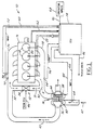
- FIG. 1 there is shown a simplified schematic diagram of a compression ignition engine system 10 equipped with an exhaust gas recirculation (EGR) system 12 and a variable geometry turbocharger (VGT) 14.
- EGR exhaust gas recirculation
- VVT variable geometry turbocharger
- a representative engine block 16 is shown having four combustion chambers 18.
- Each of the combustion chambers 18 includes a direct-injection fuel injector 20.
- the duty cycle of the fuel injectors 20 is determined by the engine control unit (ECU) 24 and transmitted along signal line 22. Air enters the combustion chambers 18 through the intake manifold 26, and combustion gases are exhausted through the exhaust manifold 28 in the direction of arrow 30.
- ECU engine control unit
- the engine is equipped with an EGR system 12.
- the EGR system 12 comprises a conduit 32 connecting the exhaust manifold 28 to the intake manifold 26. This allows a portion of the exhaust gases to be circulated from the exhaust manifold 28 to the intake manifold 26 in the direction of arrow 31.
- An EGR valve 34 regulates the amount of exhaust gas recirculated from the exhaust manifold 28.
- the recirculated exhaust gas acts as an inert gas, thus lowering the flame and in-cylinder gas temperature and decreasing the formation of NOx.
- the recirculated exhaust gas displaces fresh air and reduces the air-to-fuel ratio of the in-cylinder mixture.
- the turbocharger 14 uses exhaust gas energy to increase the mass of the air charge delivered to the engine combustion chambers 18.
- the exhaust gas flowing in the direction of arrow 30 drives the turbocharger 14. This larger mass of air can be burned with a larger quantity of fuel, resulting in more torque and power as compared to naturally aspirated, non-turbocharged engines.
- the turbocharger 14 consists of a compressor 36 and a turbine 38 coupled by a common shaft 40.
- the exhaust gas 30 drives the turbine 38 which drives the compressor 36 which, in turn, compresses ambient air 42 and directs it (arrow 43) into the intake manifold 26.
- the VGT 14 can be modified during engine operation by varying the turbine flow area and the angle at which the exhaust gas 30 is directed at the turbine blades. This is accomplished by changing the angle of the inlet guide vanes 44 on the turbine 38.
- the optimal position for the inlet guide vanes 44 is determined from the desired engine operating characteristics at various engine speeds.
- All of the engine systems, including the EGR 12, VGT 14 and fuel injectors 20 are controlled by the ECU.
- signal 46 from the ECU 24 regulates the EGR valve position
- signal 48 regulates the position of the VGT guide vanes 44.
- the command signals 46, 48 to the EGR 12 and VGT 14 actuators are calculated from measured variables and engine operating parameters by means of a control algorithm.
- Sensors and calibratable lookup tables residing in ECU memory provide the ECU 24 with engine operating information.
- MAP intake manifold pressure
- EXMP exhaust manifold pressure
- P 2 exhaust manifold pressure
- an intake manifold temperature sensor 58 provides a signal (T m ) 60 to the ECU 24 indicative of the intake manifold temperature.
- a mass airflow (MAF) sensor 64 also provides a signal (W a ) 66 indicative of the compressor mass airflow to the ECU 24.
- Additional sensory inputs can also be received by the ECU along signal line 62 such as engine coolant temperature, engine speed, and throttle position. Additional operator inputs 68 are received along signal 70 such as the accelerator pedal position or other fuelling request input.
- control block 200 generates desired set points for the compressor mass flow rate (W a *) and intake manifold pressure (P 1 * );
- control block 202 is the feedback controller to achieve the desired set points for W a and P 1 ;
- the plant or engine is represented by block 204;
- block 206 represents conventional fuel limiting schemes which may include an air density limiter and slew rate limiter.
- This invention relates primarily to the set point generator 200 and the controller 202, and their implementation in an engine control strategy.
- Control block 200 receives as inputs the engine speed ( N ), requested fuelling rate (W f ) and generates set points for the compressor flow rate (W a * ) and intake manifold pressure (P 1 * ) in order to achieve the desired AFR (AFR * ) and dilution fraction (F 1 * ).
- desired values are obtained by optimising the steady-state fuel consumption and emissions based on the engine mapping data.
- a two-dimensional grid of engine speed values and fuelling rate values is created. For each grid point, an optimal EGR valve position (X egr ) and VGT actuator position (X vgt ) is developed with reference to F 1 , smoke production, and P 1 .
- W a is measured by MAF sensor 64 of Figure 1
- W egr can be calculated from measurements of the intake manifold CO 2 concentration, exhaust manifold CO 2 concentration, and W a . Measurements for W f , W a , smoke, and CO 2 concentrations are typically recorded during engine dynamometer testing and mapping, and can be gathered by any known method.
- F 1 is preferably maximised for NOx reduction, smoke is preferably kept below an acceptable level, and the intake manifold pressure, P 1 , is preferably limited to a maximum value for overboost protection and fuel economy.
- X egr and X vgt can be developed based on the maximised weighted sum of engine brake torque and F 1 at each engine operating point.
- the weights of the summing function are experimentally selected to achieve the desired performance trade-off between NOx production and fuel consumption.
- optimised values for the performance variables F 1 and APR can be expressed as:
- optimised values for the EGR position and VGT position can be expressed as: and the corresponding values of the measured outputs can be expressed as:
- two-dimensional lookup tables are obtained for z * , u * , and y * at each engine operating point based on the engine speed and fuelling rate. If the values of the engine speed or fuelling rate do not coincide with one of the grid values, linear interpolation between grid values can be used to obtain the corresponding values for z *, u *, and y * .
- the feedback controller 202 calculates desired values for the EGR valve position and VGT actuator position to achieve the desired compressor flow rate and intake pressure.
- a compressor flow error term is established which is equal to the difference between the actual (measured) and desired compressor mass flow rates (W a -W a * ).
- an intake pressure error term is generated which is equal to the difference between the actual and desired intake manifold pressures (P 1 -P 1 * ).
- the control signals for EGR valve position and VGT actuator position are scheduled based on the optimal combinations of the deviation from the desired compressor mass air flow and intake manifold pressure in box 316. These combinations are optimised based on the performance variables, F 1 and AFR, not the measured variables.
- VGT actuator and EGR valve commands are coordinated by identifying the steady-state gains of each actuator at the optimal set points, X egr and X vgt . These gains are arranged in a 2x2 DC-gain matrix P y , shown by block 318.
- ⁇ W a , ⁇ P 1 , ⁇ X egr , ⁇ X vgt , ⁇ y , and ⁇ u correspond to deviations of the respective variables from the nominal values.
- Figure 4 shows the DC-gain matrix P z 400 which is developed to define the steady-state gains from the actuator positions for the EGR and VGT to the performance variables F 1 and AFR.
- ⁇ F 1 , ⁇ AFR, ⁇ X egr , ⁇ X vgt , ⁇ z , and ⁇ u correspond to the deviations of the respective variables from the nominal values.
- the EGR and VGT are coupled through the gains g 1 and g 2 , and the controller 516 enforces tracking of a weighted sum of the measurement errors through the gains h 1 and h 2 .
- g 1 , g 2 , h 1 and h 2 are selected to maximise the effect of the actuators on AFR and F 1 along a given direction. This is done because, in this embodiment, the actuators do not have the authority to manipulate AFR and F 1 independently.
- the gains g 1 and g 2 are calculated as follows:
- the gains h 1 and h 2 are calculated as follows:
- the gains g 1 , g 2 , h 1 , and h 2 are stored in lookup tables in ECU memory and are used to gain-schedule the controller across the entire engine operating range.
- the controller box 502 in Figure 5 is implemented using a proportional ( k p ) plus integral ( k i ) controller and is adjusted to meet the desired transient characteristics of the engine response based on the EGR valve and VGT actuator characteristics.
- k p and k i are constant values for all engine operating states whereas g 1 , g 2 , h 1 , and h 2 vary based on the engine operating state because of P z and P y .
- k p and k i could be replaced by any dynamic controller which provides a zero steady-state error.
- X c ( t +1) X c ( t )+ ⁇ t[ h 1 (W a -W a *)+ h 2 (P 1 +P 1 *)]
- X egr ( t ) X egr *( t )+ g 1 ( k i X c ( t )+ k p h 1 ((W a -W a *)+ h 2 (P 1 -P 1 * )))
- X vgt ( t ) X vgt * ( t )+ g 2 ( k i X c ( t )+ k p h 1 ((W a -W a * )+ h 2 (P 1 -P 1 * )))
- X vgt ( t ) X vgt * ( t )+ g 2 ( k i X c ( t )+ k
- X c ( t ) is the integrator state of the proportional plus integral controller. These commanded values are then applied to the actuator drivers of the EGR and VGT along signal lines 46 and 48, respectively of Figure 1.
Landscapes
- Engineering & Computer Science (AREA)
- Chemical & Material Sciences (AREA)
- Combustion & Propulsion (AREA)
- Mechanical Engineering (AREA)
- General Engineering & Computer Science (AREA)
- Combined Controls Of Internal Combustion Engines (AREA)
- Output Control And Ontrol Of Special Type Engine (AREA)
- Exhaust-Gas Circulating Devices (AREA)
Applications Claiming Priority (2)
| Application Number | Priority Date | Filing Date | Title |
|---|---|---|---|
| US09/237,418 US6076353A (en) | 1999-01-26 | 1999-01-26 | Coordinated control method for turbocharged diesel engines having exhaust gas recirculation |
| US237418 | 1999-01-26 |
Publications (2)
| Publication Number | Publication Date |
|---|---|
| EP1024264A1 true EP1024264A1 (de) | 2000-08-02 |
| EP1024264B1 EP1024264B1 (de) | 2001-10-17 |
Family
ID=22893629
Family Applications (1)
| Application Number | Title | Priority Date | Filing Date |
|---|---|---|---|
| EP00300289A Expired - Lifetime EP1024264B1 (de) | 1999-01-26 | 2000-01-17 | Steuerungsverfahren für einen turboaufgeladenen Dieselmotor mit Abgasrückführung |
Country Status (3)
| Country | Link |
|---|---|
| US (1) | US6076353A (de) |
| EP (1) | EP1024264B1 (de) |
| DE (1) | DE60000016T2 (de) |
Cited By (5)
| Publication number | Priority date | Publication date | Assignee | Title |
|---|---|---|---|---|
| EP1280990A4 (de) * | 2000-03-31 | 2004-08-11 | Detroit Diesel Corp | Verfahren zum regeln eines motors mit abgasrückführung |
| EP1519023A1 (de) * | 2003-09-25 | 2005-03-30 | Renault s.a.s. | Prozess und Einrichtung zur Steuerung eines aufgeladenen, selbstzündenden Verbrennungsmotors für ein Fahrzeug |
| FR2868126A1 (fr) * | 2004-03-29 | 2005-09-30 | Renault Sas | Procede et systeme de commande du fonctionnement d'un moteur a combustion interne de vehicule automobile equipe d'un ensemble turbocompresseur de suralimentation |
| FR2868127A1 (fr) * | 2004-03-29 | 2005-09-30 | Renault Sas | Procede et systeme de commande du fonctionnement d'un moteur a combustion interne de vehicule automobile equipe d'un ensemble turbocompresseur de suralimentation |
| DE112009005459B4 (de) * | 2009-12-21 | 2017-06-14 | Fujitsu Limited | Motorsteuerprogramm, Verfahren und Vorrichtung |
Families Citing this family (85)
| Publication number | Priority date | Publication date | Assignee | Title |
|---|---|---|---|---|
| US6951211B2 (en) | 1996-07-17 | 2005-10-04 | Bryant Clyde C | Cold air super-charged internal combustion engine, working cycle and method |
| US7222614B2 (en) | 1996-07-17 | 2007-05-29 | Bryant Clyde C | Internal combustion engine and working cycle |
| US7281527B1 (en) * | 1996-07-17 | 2007-10-16 | Bryant Clyde C | Internal combustion engine and working cycle |
| US8215292B2 (en) | 1996-07-17 | 2012-07-10 | Bryant Clyde C | Internal combustion engine and working cycle |
| JP3430923B2 (ja) * | 1998-06-15 | 2003-07-28 | 日産自動車株式会社 | 内燃機関の過給制御装置 |
| CA2393714C (en) | 1999-12-09 | 2007-01-09 | International Engine Intellectual Property Company, Llc | Closed loop diesel engine egr control including event monitoring |
| US6360541B2 (en) * | 2000-03-03 | 2002-03-26 | Honeywell International, Inc. | Intelligent electric actuator for control of a turbocharger with an integrated exhaust gas recirculation valve |
| US6305167B1 (en) * | 2000-03-31 | 2001-10-23 | Detroit Diesel Corporation | Method of controlling an engine with an EGR system |
| JP3733281B2 (ja) * | 2000-07-31 | 2006-01-11 | 株式会社豊田自動織機 | 内燃機関の過給圧制御装置および過給圧制御方法 |
| EP1195506B1 (de) * | 2000-10-05 | 2006-05-24 | Nissan Motor Co., Ltd. | Regelung eines Turboladers |
| US6363922B1 (en) | 2000-10-11 | 2002-04-02 | Detroit Diesel Corp | Exhaust gas recirculation pressure differential sensor error compensation |
| US6422219B1 (en) | 2000-11-28 | 2002-07-23 | Detroit Diesel Corporation | Electronic controlled engine exhaust treatment system to reduce NOx emissions |
| US6837227B2 (en) * | 2001-01-31 | 2005-01-04 | Cummins, Inc. | System and method for estimating EGR mass flow and EGR fraction |
| US6467469B2 (en) | 2001-01-31 | 2002-10-22 | Cummins, Inc. | EGR valve position control system |
| US6408834B1 (en) * | 2001-01-31 | 2002-06-25 | Cummins, Inc. | System for decoupling EGR flow and turbocharger swallowing capacity/efficiency control mechanisms |
| US6604361B2 (en) | 2001-11-26 | 2003-08-12 | Ford Global Technologies, Llc | Method and system for operating an engine having a turbocharger with at least two discrete positions and exhaust gas recirculation (EGR) |
| US6705301B2 (en) * | 2002-01-29 | 2004-03-16 | Cummins, Inc. | System for producing charge flow and EGR fraction commands based on engine operating conditions |
| GB2388922B (en) * | 2002-01-31 | 2005-06-08 | Cambridge Consultants | Control system |
| US6688280B2 (en) | 2002-05-14 | 2004-02-10 | Caterpillar Inc | Air and fuel supply system for combustion engine |
| US6722349B2 (en) | 2002-02-04 | 2004-04-20 | Caterpillar Inc | Efficient internal combustion engine valve actuator |
| US6732685B2 (en) | 2002-02-04 | 2004-05-11 | Caterpillar Inc | Engine valve actuator |
| US7201121B2 (en) | 2002-02-04 | 2007-04-10 | Caterpillar Inc | Combustion engine including fluidically-driven engine valve actuator |
| US7347171B2 (en) * | 2002-02-04 | 2008-03-25 | Caterpillar Inc. | Engine valve actuator providing Miller cycle benefits |
| US7178492B2 (en) | 2002-05-14 | 2007-02-20 | Caterpillar Inc | Air and fuel supply system for combustion engine |
| US7004122B2 (en) * | 2002-05-14 | 2006-02-28 | Caterpillar Inc | Engine valve actuation system |
| US7191743B2 (en) | 2002-05-14 | 2007-03-20 | Caterpillar Inc | Air and fuel supply system for a combustion engine |
| US7252054B2 (en) | 2002-05-14 | 2007-08-07 | Caterpillar Inc | Combustion engine including cam phase-shifting |
| US7069887B2 (en) | 2002-05-14 | 2006-07-04 | Caterpillar Inc. | Engine valve actuation system |
| US6941909B2 (en) * | 2003-06-10 | 2005-09-13 | Caterpillar Inc | System and method for actuating an engine valve |
| DE50211459D1 (de) * | 2002-06-26 | 2008-02-14 | Borgwarner Inc | Motorbremseinrichtung für eine turboaufgeladene Brennkraftmaschine |
| US6672060B1 (en) | 2002-07-30 | 2004-01-06 | Ford Global Technologies, Llc | Coordinated control of electronic throttle and variable geometry turbocharger in boosted stoichiometric spark ignition engines |
| US6716136B2 (en) | 2002-08-29 | 2004-04-06 | Ford Global Technologies, Llc | Powertrain control method for minimizing effects of engine torque disturbances |
| US6716137B1 (en) | 2002-08-29 | 2004-04-06 | Ford Global Technologies, Llc | Method for controlling camless engine having an automatically controlled transmission |
| US6738702B2 (en) | 2002-08-29 | 2004-05-18 | Ford Global Technologies, Llc | Method for particulate filter regeneration in vehicles having an automatically controlled transmission |
| US6912458B2 (en) * | 2003-06-25 | 2005-06-28 | Caterpillar Inc | Variable valve actuation control for operation at altitude |
| US6929582B2 (en) * | 2003-10-01 | 2005-08-16 | Ford Global Technologies, Llc | Method for controlling variable compression ratio of an engine having an automatically controlled transmission |
| US6850834B1 (en) * | 2003-11-17 | 2005-02-01 | Ford Global Technologies, Llc | Method and system for detecting degradation of EGR flow delivery |
| US7031824B2 (en) * | 2004-04-07 | 2006-04-18 | General Motors Corporation | Multivariable actuator control for an internal combustion engine |
| JP2006029247A (ja) * | 2004-07-20 | 2006-02-02 | Denso Corp | エンジンの停止始動制御装置 |
| US7743606B2 (en) * | 2004-11-18 | 2010-06-29 | Honeywell International Inc. | Exhaust catalyst system |
| US7182075B2 (en) * | 2004-12-07 | 2007-02-27 | Honeywell International Inc. | EGR system |
| US7467614B2 (en) | 2004-12-29 | 2008-12-23 | Honeywell International Inc. | Pedal position and/or pedal change rate for use in control of an engine |
| US7591135B2 (en) * | 2004-12-29 | 2009-09-22 | Honeywell International Inc. | Method and system for using a measure of fueling rate in the air side control of an engine |
| US7275374B2 (en) * | 2004-12-29 | 2007-10-02 | Honeywell International Inc. | Coordinated multivariable control of fuel and air in engines |
| US7328577B2 (en) | 2004-12-29 | 2008-02-12 | Honeywell International Inc. | Multivariable control for an engine |
| US7165399B2 (en) * | 2004-12-29 | 2007-01-23 | Honeywell International Inc. | Method and system for using a measure of fueling rate in the air side control of an engine |
| US7752840B2 (en) * | 2005-03-24 | 2010-07-13 | Honeywell International Inc. | Engine exhaust heat exchanger |
| DE102005015609B4 (de) * | 2005-04-05 | 2008-01-17 | Siemens Ag | Vorrichtung zum Steuern einer Brennkraftmaschine |
| US7469177B2 (en) * | 2005-06-17 | 2008-12-23 | Honeywell International Inc. | Distributed control architecture for powertrains |
| DE102006023575A1 (de) * | 2005-07-18 | 2007-02-01 | Daimlerchrysler Ag | Vorrichtung zur Verbrennungsmotor-/Antriebsstrangsteuerung für ein Kraftfahrzeug |
| US7389773B2 (en) | 2005-08-18 | 2008-06-24 | Honeywell International Inc. | Emissions sensors for fuel control in engines |
| US7155334B1 (en) | 2005-09-29 | 2006-12-26 | Honeywell International Inc. | Use of sensors in a state observer for a diesel engine |
| US7765792B2 (en) * | 2005-10-21 | 2010-08-03 | Honeywell International Inc. | System for particulate matter sensor signal processing |
| US7357125B2 (en) * | 2005-10-26 | 2008-04-15 | Honeywell International Inc. | Exhaust gas recirculation system |
| US20070144149A1 (en) * | 2005-12-28 | 2007-06-28 | Honeywell International Inc. | Controlled regeneration system |
| US7415389B2 (en) * | 2005-12-29 | 2008-08-19 | Honeywell International Inc. | Calibration of engine control systems |
| US7958730B2 (en) * | 2005-12-30 | 2011-06-14 | Honeywell International Inc. | Control of dual stage turbocharging |
| US7320219B2 (en) * | 2006-03-10 | 2008-01-22 | Detroit Diesel Corporation | Method for controlling an internal combustion engine using model based VGT/EGR control |
| US7296562B2 (en) * | 2006-03-30 | 2007-11-20 | Caterpiller Inc. | Control system and method for estimating turbocharger performance |
| FR2909132B1 (fr) * | 2006-11-27 | 2009-02-27 | Renault Sas | Procede de regulation de pression dans un collecteur d'admission d'un moteur a combustion interne dote de turbocompresseurs |
| US7614231B2 (en) * | 2007-04-09 | 2009-11-10 | Detroit Diesel Corporation | Method and system to operate diesel engine using real time six dimensional empirical diesel exhaust pressure model |
| GB0713951D0 (en) * | 2007-07-18 | 2007-08-29 | Cummins Turbo Tech Ltd | Calibration of an actuator for a variable geometry turbine |
| US8060290B2 (en) | 2008-07-17 | 2011-11-15 | Honeywell International Inc. | Configurable automotive controller |
| US8620461B2 (en) | 2009-09-24 | 2013-12-31 | Honeywell International, Inc. | Method and system for updating tuning parameters of a controller |
| JP5333120B2 (ja) * | 2009-09-25 | 2013-11-06 | 富士通株式会社 | エンジン制御プログラム、方法及び装置 |
| JP5249898B2 (ja) * | 2009-09-29 | 2013-07-31 | 富士通株式会社 | エンジン制御プログラム、方法及び装置 |
| US8504175B2 (en) | 2010-06-02 | 2013-08-06 | Honeywell International Inc. | Using model predictive control to optimize variable trajectories and system control |
| JP5310954B2 (ja) * | 2010-09-08 | 2013-10-09 | トヨタ自動車株式会社 | 内燃機関の制御装置 |
| DE102010060992A1 (de) * | 2010-12-02 | 2012-06-06 | Fev Gmbh | Ladedruckgeführtes Regelverfahren für eine Brennkraftmaschine |
| JP5854662B2 (ja) * | 2011-06-28 | 2016-02-09 | 三菱重工業株式会社 | 内燃機関の制御装置および方法 |
| US9677493B2 (en) | 2011-09-19 | 2017-06-13 | Honeywell Spol, S.R.O. | Coordinated engine and emissions control system |
| US9650934B2 (en) | 2011-11-04 | 2017-05-16 | Honeywell spol.s.r.o. | Engine and aftertreatment optimization system |
| US20130111905A1 (en) | 2011-11-04 | 2013-05-09 | Honeywell Spol. S.R.O. | Integrated optimization and control of an engine and aftertreatment system |
| US9574489B2 (en) | 2012-06-07 | 2017-02-21 | Boise State University | Multi-stage turbo with continuous feedback control |
| EP3051367B1 (de) | 2015-01-28 | 2020-11-25 | Honeywell spol s.r.o. | Ansatz und system zur handhabung von einschränkungen für gemessene störungen mit unsicherer vorschau |
| EP3056706A1 (de) | 2015-02-16 | 2016-08-17 | Honeywell International Inc. | Ansatz zur nachbehandlungssystemmodellierung und modellidentifizierung |
| EP3091212A1 (de) | 2015-05-06 | 2016-11-09 | Honeywell International Inc. | Identifikationsansatz für verbrennungsmotor-mittelwertmodelle |
| EP3125052B1 (de) | 2015-07-31 | 2020-09-02 | Garrett Transportation I Inc. | Quadratischer programmlöser für mpc mit variabler anordnung |
| US10272779B2 (en) | 2015-08-05 | 2019-04-30 | Garrett Transportation I Inc. | System and approach for dynamic vehicle speed optimization |
| IL241683B (en) | 2015-09-17 | 2020-09-30 | Israel Aerospace Ind Ltd | Multi-serial charger |
| US10415492B2 (en) | 2016-01-29 | 2019-09-17 | Garrett Transportation I Inc. | Engine system with inferential sensor |
| US10124750B2 (en) | 2016-04-26 | 2018-11-13 | Honeywell International Inc. | Vehicle security module system |
| US10036338B2 (en) | 2016-04-26 | 2018-07-31 | Honeywell International Inc. | Condition-based powertrain control system |
| EP3548729B1 (de) | 2016-11-29 | 2023-02-22 | Garrett Transportation I Inc. | Inferenzflusssensor |
| US11057213B2 (en) | 2017-10-13 | 2021-07-06 | Garrett Transportation I, Inc. | Authentication system for electronic control unit on a bus |
Citations (5)
| Publication number | Priority date | Publication date | Assignee | Title |
|---|---|---|---|---|
| US4622816A (en) * | 1983-02-03 | 1986-11-18 | Office National D'etudes Et De Recherches Aerospatiales (Par Abreviation O.N.E.R.A.) | Internal combustion engine supercharged by turbocompressor |
| US5187935A (en) * | 1988-12-26 | 1993-02-23 | Honda Giken Kogyo Kabushiki Kaisha | Engine control device |
| US5520161A (en) * | 1995-07-17 | 1996-05-28 | Alternative Fuel Sytems Inc. | Exhaust gas recirculation system for a compression ignition engine and a method of controlling exhaust gas recirculation in a compression ignition engine |
| DE19728352C1 (de) * | 1997-07-03 | 1998-08-20 | Daimler Benz Ag | Verfahren zur Regelung der Aufladung einer Brennkraftmaschine mit einem Abgasturbolader mit verstellbarer Turbinengeometrie |
| EP0965740A2 (de) * | 1998-06-15 | 1999-12-22 | Nissan Motor Co., Ltd. | Turboladersteuersystem für aufgeladene Verbrennungsmotoren, die mit einem geregelten Abgasrückführungssystem ausgerüstet sind |
Family Cites Families (11)
| Publication number | Priority date | Publication date | Assignee | Title |
|---|---|---|---|---|
| CH610987A5 (de) * | 1975-08-29 | 1979-05-15 | Bbc Brown Boveri & Cie | |
| DE2706696C2 (de) * | 1977-02-17 | 1982-04-29 | Mtu Motoren- Und Turbinen-Union Friedrichshafen Gmbh, 7990 Friedrichshafen | Verfahren zum Anlassen der Brennkammer einer Brennkraftmaschine |
| US4249382A (en) * | 1978-05-22 | 1981-02-10 | Caterpillar Tractor Co. | Exhaust gas recirculation system for turbo charged engines |
| US5228292A (en) * | 1990-08-16 | 1993-07-20 | Mercedes-Benz Ag | Arrangement for controlling the boost pressure in an internal-combustion engine supercharged by an exhaust-gas turbocharger of adjustable turbine geometry |
| US5273019A (en) * | 1990-11-26 | 1993-12-28 | General Motors Corporation | Apparatus with dynamic prediction of EGR in the intake manifold |
| US5123246A (en) * | 1991-01-25 | 1992-06-23 | Mack Trucks, Inc. | Continuously proportional variable geometry turbocharger system and method of control |
| DE69530721T2 (de) * | 1994-04-14 | 2004-03-18 | Honda Giken Kogyo K.K. | System zur Schätzung der Abgasrückführungsrate für einen Verbrennungsmotor |
| NL1000119C2 (nl) * | 1995-04-11 | 1996-10-14 | Tno | Uitlaatgasrecirculatiesysteem voor een inwendige verbrandingsmotor. |
| JP3298358B2 (ja) * | 1995-04-25 | 2002-07-02 | 日産自動車株式会社 | ディーゼルエンジンにおける圧縮端温度制御方法および制御装置 |
| EP0774574B1 (de) * | 1995-06-02 | 2006-11-08 | Mitsubishi Jidosha Kogyo Kabushiki Kaisha | Vorrichtung zum erfassen und steurern des luftüberschussfaktors einer brennkraftmaschine |
| US5771867A (en) * | 1997-07-03 | 1998-06-30 | Caterpillar Inc. | Control system for exhaust gas recovery system in an internal combustion engine |
-
1999
- 1999-01-26 US US09/237,418 patent/US6076353A/en not_active Expired - Fee Related
-
2000
- 2000-01-17 DE DE60000016T patent/DE60000016T2/de not_active Expired - Fee Related
- 2000-01-17 EP EP00300289A patent/EP1024264B1/de not_active Expired - Lifetime
Patent Citations (5)
| Publication number | Priority date | Publication date | Assignee | Title |
|---|---|---|---|---|
| US4622816A (en) * | 1983-02-03 | 1986-11-18 | Office National D'etudes Et De Recherches Aerospatiales (Par Abreviation O.N.E.R.A.) | Internal combustion engine supercharged by turbocompressor |
| US5187935A (en) * | 1988-12-26 | 1993-02-23 | Honda Giken Kogyo Kabushiki Kaisha | Engine control device |
| US5520161A (en) * | 1995-07-17 | 1996-05-28 | Alternative Fuel Sytems Inc. | Exhaust gas recirculation system for a compression ignition engine and a method of controlling exhaust gas recirculation in a compression ignition engine |
| DE19728352C1 (de) * | 1997-07-03 | 1998-08-20 | Daimler Benz Ag | Verfahren zur Regelung der Aufladung einer Brennkraftmaschine mit einem Abgasturbolader mit verstellbarer Turbinengeometrie |
| EP0965740A2 (de) * | 1998-06-15 | 1999-12-22 | Nissan Motor Co., Ltd. | Turboladersteuersystem für aufgeladene Verbrennungsmotoren, die mit einem geregelten Abgasrückführungssystem ausgerüstet sind |
Cited By (7)
| Publication number | Priority date | Publication date | Assignee | Title |
|---|---|---|---|---|
| EP1280990A4 (de) * | 2000-03-31 | 2004-08-11 | Detroit Diesel Corp | Verfahren zum regeln eines motors mit abgasrückführung |
| EP1519023A1 (de) * | 2003-09-25 | 2005-03-30 | Renault s.a.s. | Prozess und Einrichtung zur Steuerung eines aufgeladenen, selbstzündenden Verbrennungsmotors für ein Fahrzeug |
| FR2860268A1 (fr) * | 2003-09-25 | 2005-04-01 | Renault Sa | Procede et dispositif de controle du fonctionnement d'un moteur a allumage par compression de vehicule automobile, suralimente en air |
| FR2868126A1 (fr) * | 2004-03-29 | 2005-09-30 | Renault Sas | Procede et systeme de commande du fonctionnement d'un moteur a combustion interne de vehicule automobile equipe d'un ensemble turbocompresseur de suralimentation |
| FR2868127A1 (fr) * | 2004-03-29 | 2005-09-30 | Renault Sas | Procede et systeme de commande du fonctionnement d'un moteur a combustion interne de vehicule automobile equipe d'un ensemble turbocompresseur de suralimentation |
| EP1582718A1 (de) * | 2004-03-29 | 2005-10-05 | Renault s.a.s. | Verfahren und Vorrichtung zur Steuerung einer Brennkraftmaschine in einem Kraftfahrzeug |
| DE112009005459B4 (de) * | 2009-12-21 | 2017-06-14 | Fujitsu Limited | Motorsteuerprogramm, Verfahren und Vorrichtung |
Also Published As
| Publication number | Publication date |
|---|---|
| EP1024264B1 (de) | 2001-10-17 |
| US6076353A (en) | 2000-06-20 |
| DE60000016T2 (de) | 2003-11-20 |
| DE60000016D1 (de) | 2001-11-22 |
Similar Documents
| Publication | Publication Date | Title |
|---|---|---|
| EP1024264B1 (de) | Steuerungsverfahren für einen turboaufgeladenen Dieselmotor mit Abgasrückführung | |
| EP1024272B1 (de) | Steuerungsverfahren für einen turboaufgeladenen Dieselmotor mit Abgasrückführung | |
| EP1024263B1 (de) | Steuerungsverfahren für einen turboaufgeladenen Dieselmotor mit Abgasrückführung | |
| EP1024275B1 (de) | Kraftstoffbegrenzungsmethode für eine Dieselbrennkraftmaschine mit Abgasrückführung | |
| EP1024260B1 (de) | Steuerungsverfahren für einen Turbolader variabler Geometrie in einem Dieselmotor mit Abgasrückführung | |
| US6035639A (en) | Method of estimating mass airflow in turbocharged engines having exhaust gas recirculation | |
| US8630787B2 (en) | Controlling exhaust gas recirculation in a turbocharged engine system | |
| US7150264B2 (en) | Control device for internal combustion engine | |
| US7380400B2 (en) | System and method for high pressure and low pressure exhaust gas recirculation control and estimation | |
| EP2292915B1 (de) | Steuerung zur Abgasrückführung in turboaufgeladenen Brennkraftmaschinen | |
| US7878178B2 (en) | Emissions sensors for fuel control in engines | |
| US8601813B2 (en) | Controlling exhaust gas recirculation in a turbocharged engine system | |
| US6178749B1 (en) | Method of reducing turbo lag in diesel engines having exhaust gas recirculation | |
| US7275374B2 (en) | Coordinated multivariable control of fuel and air in engines | |
| US20050228573A1 (en) | Multivariable actuator control for an internal combustion engine | |
| GB2434406A (en) | I.c. engine exhaust gas recirculation (EGR) system with dual high pressure and low pressure EGR loops | |
| CN101307717A (zh) | 涡轮增压器轴超速补偿 | |
| CN102003296A (zh) | 进气集管氧控制 | |
| JP2008261300A (ja) | 内燃機関の排気還流装置 | |
| US7140360B2 (en) | System for controlling exhaust emissions produced by an internal combustion engine | |
| EP1245818B1 (de) | Vorrichtung und Verfahren zur Steuerung des Luft-Kraftstoff-Verhältnises einer Brennkraftmaschine | |
| JP4228953B2 (ja) | 内燃機関の制御装置 |
Legal Events
| Date | Code | Title | Description |
|---|---|---|---|
| PUAI | Public reference made under article 153(3) epc to a published international application that has entered the european phase |
Free format text: ORIGINAL CODE: 0009012 |
|
| AK | Designated contracting states |
Kind code of ref document: A1 Designated state(s): DE FR GB |
|
| AX | Request for extension of the european patent |
Free format text: AL;LT;LV;MK;RO;SI |
|
| 17P | Request for examination filed |
Effective date: 20010116 |
|
| GRAG | Despatch of communication of intention to grant |
Free format text: ORIGINAL CODE: EPIDOS AGRA |
|
| AKX | Designation fees paid |
Free format text: DE FR GB |
|
| 17Q | First examination report despatched |
Effective date: 20010329 |
|
| GRAG | Despatch of communication of intention to grant |
Free format text: ORIGINAL CODE: EPIDOS AGRA |
|
| GRAH | Despatch of communication of intention to grant a patent |
Free format text: ORIGINAL CODE: EPIDOS IGRA |
|
| GRAH | Despatch of communication of intention to grant a patent |
Free format text: ORIGINAL CODE: EPIDOS IGRA |
|
| GRAA | (expected) grant |
Free format text: ORIGINAL CODE: 0009210 |
|
| AK | Designated contracting states |
Kind code of ref document: B1 Designated state(s): DE FR GB |
|
| REF | Corresponds to: |
Ref document number: 60000016 Country of ref document: DE Date of ref document: 20011122 |
|
| REG | Reference to a national code |
Ref country code: GB Ref legal event code: IF02 |
|
| ET | Fr: translation filed | ||
| PLBE | No opposition filed within time limit |
Free format text: ORIGINAL CODE: 0009261 |
|
| STAA | Information on the status of an ep patent application or granted ep patent |
Free format text: STATUS: NO OPPOSITION FILED WITHIN TIME LIMIT |
|
| 26N | No opposition filed | ||
| REG | Reference to a national code |
Ref country code: GB Ref legal event code: 732E |
|
| PGFP | Annual fee paid to national office [announced via postgrant information from national office to epo] |
Ref country code: GB Payment date: 20031211 Year of fee payment: 5 |
|
| PGFP | Annual fee paid to national office [announced via postgrant information from national office to epo] |
Ref country code: FR Payment date: 20040102 Year of fee payment: 5 |
|
| PGFP | Annual fee paid to national office [announced via postgrant information from national office to epo] |
Ref country code: DE Payment date: 20040130 Year of fee payment: 5 |
|
| PG25 | Lapsed in a contracting state [announced via postgrant information from national office to epo] |
Ref country code: GB Free format text: LAPSE BECAUSE OF NON-PAYMENT OF DUE FEES Effective date: 20050117 |
|
| REG | Reference to a national code |
Ref country code: FR Ref legal event code: TP |
|
| PG25 | Lapsed in a contracting state [announced via postgrant information from national office to epo] |
Ref country code: DE Free format text: LAPSE BECAUSE OF NON-PAYMENT OF DUE FEES Effective date: 20050802 |
|
| GBPC | Gb: european patent ceased through non-payment of renewal fee |
Effective date: 20050117 |
|
| PG25 | Lapsed in a contracting state [announced via postgrant information from national office to epo] |
Ref country code: FR Free format text: LAPSE BECAUSE OF NON-PAYMENT OF DUE FEES Effective date: 20050930 |
|
| REG | Reference to a national code |
Ref country code: FR Ref legal event code: ST |