EP1024042B1 - Faltverdeck für ein Cabriolet-Fahrzeug - Google Patents
Faltverdeck für ein Cabriolet-Fahrzeug Download PDFInfo
- Publication number
- EP1024042B1 EP1024042B1 EP99125467A EP99125467A EP1024042B1 EP 1024042 B1 EP1024042 B1 EP 1024042B1 EP 99125467 A EP99125467 A EP 99125467A EP 99125467 A EP99125467 A EP 99125467A EP 1024042 B1 EP1024042 B1 EP 1024042B1
- Authority
- EP
- European Patent Office
- Prior art keywords
- strut
- foldable top
- bar
- top according
- foldable
- Prior art date
- Legal status (The legal status is an assumption and is not a legal conclusion. Google has not performed a legal analysis and makes no representation as to the accuracy of the status listed.)
- Expired - Lifetime
Links
- 230000001747 exhibiting effect Effects 0.000 claims 2
- 239000004744 fabric Substances 0.000 description 10
- 238000006073 displacement reaction Methods 0.000 description 3
- 230000000712 assembly Effects 0.000 description 2
- 238000000429 assembly Methods 0.000 description 2
- 238000000034 method Methods 0.000 description 2
- 239000013641 positive control Substances 0.000 description 2
- 230000006735 deficit Effects 0.000 description 1
- 238000010586 diagram Methods 0.000 description 1
- 230000000694 effects Effects 0.000 description 1
- 239000011521 glass Substances 0.000 description 1
- 230000010354 integration Effects 0.000 description 1
- 239000000463 material Substances 0.000 description 1
- 239000012528 membrane Substances 0.000 description 1
- 230000000007 visual effect Effects 0.000 description 1
Images

Classifications
-
- B—PERFORMING OPERATIONS; TRANSPORTING
- B60—VEHICLES IN GENERAL
- B60J—WINDOWS, WINDSCREENS, NON-FIXED ROOFS, DOORS, OR SIMILAR DEVICES FOR VEHICLES; REMOVABLE EXTERNAL PROTECTIVE COVERINGS SPECIALLY ADAPTED FOR VEHICLES
- B60J7/00—Non-fixed roofs; Roofs with movable panels, e.g. rotary sunroofs
- B60J7/08—Non-fixed roofs; Roofs with movable panels, e.g. rotary sunroofs of non-sliding type, i.e. movable or removable roofs or panels, e.g. let-down tops or roofs capable of being easily detached or of assuming a collapsed or inoperative position
- B60J7/12—Non-fixed roofs; Roofs with movable panels, e.g. rotary sunroofs of non-sliding type, i.e. movable or removable roofs or panels, e.g. let-down tops or roofs capable of being easily detached or of assuming a collapsed or inoperative position foldable; Tensioning mechanisms therefor, e.g. struts
- B60J7/1226—Soft tops for convertible vehicles
- B60J7/1265—Soft tops for convertible vehicles characterised by kinematic movements, e.g. using parallelogram linkages
Definitions
- the invention relates to a folding top for a convertible vehicle in training according to the preamble disclosed in US 5816644 of claim 1.
- the invention addresses the problem of a convertible vehicle with a folding top by Jerner according to DE 295 13 595.6 to create known type, the top kinematics with little technical effort in the opening or closing movement a reduced impairment of the hood enabled by vehicle occupants and a total of one has improved ease of use.
- the folding top according to the invention has in the rear area of its two folding link assemblies on the edge one each from the main pillar known per se and one existing on this externally articulated strut, two-part linkage group as connection unit to the roof skin.
- This strut is on the longitudinal edge connected to an area of the roof skin so that one of the main pillar is connected independently and the rear area of the roof skin is also independent of be tensioned or relaxed during the movement of the main column can.
- the one integrated into the roof membrane in the rear area Rear window can with this convertible top kinematics shift an enlarged adjustment range so that the support components come to a high position and one above the rear area of the vehicle as headroom effective trajectory is traversed.
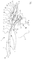
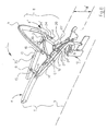
- Fig. 1 is a partially sectioned side view a folding top designated as 1 for a illustrates a convertible vehicle, not shown, whose roof skin 2 is between both sides of the vehicle longitudinal median plane 3 (Fig. 5) symmetrically opposite Linkage legs 4 each in the closed position in the area of the windshield frame (not shown) definable folding linkage assembly 5 extends.
- the roof skin 3 is in the rear area of the Folding top 1 between a top clamp 6 and one rear corner bow 7 with a preferably Fixed glass existing rear window 8 provided.
- the two folding linkage assemblies 5 (of which in the Drawings shown only one or below described) have in a known convertible top kinematics towards the rear of the vehicle, one with a Drive member 9 connected and body side in one Main pivot bearing 10 supported main column 11, in their near range to the vehicle longitudinal median plane 3 inner guide rod pivotable in synchronism with the main column 11 12 is provided (Fig. 5).
- the convertible top kinematics designed according to the invention has a main column 11 with an outside on this Articulated strut 13 is provided on the the roof skin 2 attacks at least in places along the longitudinal edge (not shown). 1 illustrates that the expansion strut 13 in the closed position of the folding top 1 on the outside in front of the main pillar 11 a cover position with a substantially parallel orientation to the main pillar 11.
- FIG. 1 and Fig. 2 illustrates the Sequence of movements in a first phase during the opening movement of the folding linkage 5, the expansion strut 13 in this movement phase pivoted independently of the main column 11 is and against the direction of travel in the illustrated Spread position (Fig. 2) is shifted. If continued the opening movement of the folding top 1 (Fig. 3, Fig. 4) the expansion strut 13 from its spread position in the parallel cover position on the outside in front of the main column 11 returned (Fig. 3) and then the Spreader strut 13 and the main pillar 11 at the same time Swiveling movement with the parts of the folding linkage 5 in the The convertible top compartment 14 of the vehicle is folded in (FIG. 4).
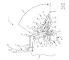
- the expansion strut 13 is in the movement phase according to FIG. 2 in its spreading position over the main column 11 directional links held up as one way the integration of the expansion strut 13 in the top kinematics in a perspective rear view according to Fig. 6 are shown in more detail. It becomes clear that between the main column 11 and the strut 13 with a front link lever 15 and a rear link lever 16 provided linkage is provided, the total a four-link chain A, B, C, D in the manner of a parallelogram control forms.
- FIG. 2 clarified.
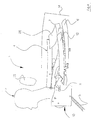
- the essentially true-to-scale representation shows with the trajectory R (dash-dot line) and the movement arrow R 'the possible pivot positions the rear window 8 during the opening process, while by means of the top kinematics according to the invention with the Spreader strut 13 of the front window edge 17 of the rear window 8 no longer forward into the field of vision of the passenger P is shifted, and this throughout Opening or. Closing cycle (Fig. 1 to Fig. 4) unaffected from the movement of the top 1 in the vehicle can remain.
- the expansion strut 13 For a positively controlled movement of the expansion strut 13 by means of the top kinematics, the expansion strut 13 in Area of the articulation parts 15, 16 in the folding linkage 5 integrated that one in the area of the main drive member 9 generated movement of the folding top 1 via constructive selectable connecting components, for example via one of the rod legs 4, one of the corner bow 7 and / or the rear-side convertible top clamp 6 on which Spreader strut 13 can be transmitted.
- positive control is the Spreader strut 13 by means of the convertible top tensioning bracket acting on this 6 provided. It is also conceivable that the Spreader strut 13 for displacement in the above Relaxation position of the roof skin 2 (Fig. 2) with a separate Drive member (not shown) is provided.
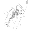
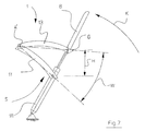
- Fig. 7 is a constructive principle simple implementation of the convertible top kinematics with the expanding strut 13 and the convertible top tensioning bracket 6.
- the Convertible top tensioning bracket 6 engages on an overall designated S Swivel-stroke assembly in a swivel joint G to that together with the convertible top clamp 6 in one vertical distance H to the main pivot bearing 10 (or to the bodywork not shown) Superscript is shiftable.
- the convertible top clamp 6 during the height shift (distance H) against the Direction of travel swiveled up (arrow K), with the convertible top clamp 6 in the area of the swivel-stroke assembly S with a lifting element formed by a hydraulic cylinder 18 interacts.
- the swivel joint G is an end connection between the convertible top tensioning bracket 6 and the expansion strut 13 provided so that this in the first opening phase of Folding top 1 positively controlled under pivoting around as Fixed pivot point shown hinge A '(in Fig. 6 as a movable Legs 15 with articulation points A and B) in the spreading position defining an angle W. is shifted to the main pillar 11.
- Fixed pivot point shown hinge A '(in Fig. 6 as a movable Legs 15 with articulation points A and B) in the spreading position defining an angle W. is shifted to the main pillar 11.
- About a corresponding one Dimensioning the distance H using a vehicle-specific Dimensioning of the parts of the swivel-stroke assembly S can meet these different demands on the trajectory the rear window 8 and / or the required headroom above the passenger compartment.
- Folding top 1 with the expansion strut 13 is at the back end of a multi-part Link chain E with the rear area of the Roof tension clamp 6 capturing roof skin 2 (FIG. 5, FIG. 6) connected.
- the convertible top tensioning bracket 6 has one angled and in the closed position (Fig. 1) directed upwards
- Support leg 20 on the main bearing 10 out in the area of the main column 11 with an oscillating strut 21 forms respective hinge points L, L 'and on the body side is articulated via a support strut 21 '(FIG. 6).
- the convertible top tensioning bracket 6 thus has one in the articulation point L. at a distance H 'above the fulcrum with which the distance H according to FIG. 7 at Opening movement corresponding height shift as a fixed Dimension is included in the design, being for relocation of the convertible top clamp 6 in the swung open Position of the pivot point L at its height in the Body is arranged so that one over the parapet support area is reached and with this inevitably the increased trajectory R results.
- the roof skin 2 has in its rear area between the corner bow 7 and the convertible top clamp 6 the Rear window 8 on the opening or closing movement of the folding top 1 on that of the expansion strut 13 and the respective swivel assembly (S in Fig. 7; E in Fig. 6) of the convertible top clamp 6 defined trajectory R is guided so that the interior of the vehicle with the Passenger P is largely unaffected.
- the rear window 8 is over to the rear tensioning strut 23 an angle lever 26 articulated so that the rear window 8th positively guided with the movement of the tension strut 23 in the 2 comes up here and over here the angle part 26 'a stable support of the substantially vertically aligned rear window 8 reached is.
- the convertible top kinematics in Area of the expansion strut 13 or of the convertible top tensioning bracket 6 a gas pressure spring 27 supported on the main pivot bearing 10 so that the rear components of the folding linkage 5 in the open position (Fig. 2) against an unwanted downward movement are secured, the convertible top compartment lid (not shown) can be opened freely and then the shift of the folding top 2 to the storage position (Fig. 4) in the convertible top compartment 14 is possible.
- the convertible top fabric tensioning bracket opens 6 to the almost vertical position (Fig. 2) on the Area of the headrest 29 on, with a pivoting movement around the pivot point L.
- the rear window 8 is about the above described and shown convertible top kinematics in a to the level of the top fabric tensioning bracket 6 spent essentially parallel position and this is located behind the head area of a rear passenger P.
- the expansion strut 13 is in this movement their connecting parts to the convertible top fabric clamp 6 positively controlled raised and this will cause the rear fabric to be covered (not shown) of the roof skin 2 by means of Spreader strut adjusted so that no additional tension occur in the roof skin 2.
- the one in the area Connection lugs 30, 30 '(Fig. 6) on the expansion strut 13 articulated corner bows 7, 7 'and 7 "follow the movement described above, with a discharge the roof skin 2 takes place.
Landscapes
- Engineering & Computer Science (AREA)
- Mechanical Engineering (AREA)
- Body Structure For Vehicles (AREA)
- Rear-View Mirror Devices That Are Mounted On The Exterior Of The Vehicle (AREA)
- Tents Or Canopies (AREA)
Description
- Fig.1
- eine Seitenansicht des ohne Dachhaut dargestellten Faltverdecks in Schließstellung,
- Fig. 2
- eine Seitenansicht ähnlich Fig. 1 in einer ersten Öffnungsphase bei Verstellung eines Verdeckstoff- Spannbügels und einer Spreizstrebe,
- Fig. 3
- eine zweite Öffnungsphase bei Bewegung des Klappgestänges zu einem heckseitigen Verdeckkasten hin,
- Fig. 4
- eine Seitenansicht mit im Verdeckkasten befindlichen Faltverdeck,
- Fig. 5
- eine perspektivische Ausschnittsdarstellung des Klappgestänges im Bereich der Hauptsäule in Schließstellung,
- Fig. 6
- eine Perspektivdarstellung ähnlich Fig. 5 während der Öffnungsphase gemäß Fig. 2 mit hochgeschwenktem Verdeckstoff-Spannbügel, und
- Fig. 7
- eine Prinzipdarstellung einer zweiten Ausführung der Spreizstrebe mit direkt an dieser angelenktem Verdeckstoff-Spannbügel.
Claims (16)
- Faltverdeck für ein Cabriolet-Fahrzeug, dessen eine Heckscheibe (8), einen heckseitigen Verdeckspannbügel (6) und zumindest einen Eckspriegel (7) aufweisende Dachhaut (2) längsrandseitig zwischen zwei spielgelbildlich zur Fahrzeuglängsmittelebene (3) verlaufenden, mehrgliedrigen Klappgestänge-Baugruppen (5) aufgenommen ist, die zum Fahrzeugheckbereich hin jeweils eine mit einem Haupt-Antriebsorgan (9) verbundene und karosserieseitig in einem Hauptschwenklager (10) abgestützte Hauptsäule (11) aufweisen, und in deren Nahbereich zur Fahrzeuglängsmittelebene (3) hin jeweils eine synchron mit der Hauptsäule (11) schwenkbare innere Führungsstange (12) vorgesehen ist, dadurch gekennzeichnet, daß an der Hauptsäule (11) eine äußere Spreizstrebe (13) angelenkt und diese längsrandseitig zumindest bereichsweise mit der Dachhaut (2) verbunden ist, derart, daß die Spreizstrebe (13) in der Schließstellung des Faltverdecks (1) außenseitig vor der Hauptsäule (11) eine Abdeckstellung einnimmt.
- Faltverdeck nach Anspruch 1, dadurch gekennzeichnet, daß die Spreizstrebe (13) eine Abdeckstellung mit im wesentlichen paralleler Ausrichtung zur Hauptsäule (11) aufweist.
- Faltverdeck nach Anspruch 1 oder 2, dadurch gekennzeichnet, daß die Spreizstrebe (13) bei der Öffnungsbewegung der Klappgestänge-Baugrappe (5) zumindest phasenweise unabhängig von der Hauptsäule (11) verstellbar, dabei entgegen der Fahrtrichtung in eine Spreizstellung (Winkel W) hochschwenkbar und aus dieser in die parallele Abdeckstellung außenseitig vor der Hauptsäule (11) rückführbar ist.
- Faltverdeck nach einem der Ansprüche 1 bis 3, dadurch gekennzeichnet, daß die Spreizstrebe (13) und die Hauptsäule (11) gleichzeitig verschwenkbar sind.
- Faltverdeck nach einem der Ansprüche 1 bis 4, dadurch gekennzeichnet, daß zwischen der Hauptsäule (11) und der Spreizstrebe (13) eine mit einem vorderen (15) und einem hinteren Gelenkhebel (16) eine Viergelenkkette (A, B, C, D) bildende Anlenkung vorgesehen ist.
- Faltverdeck nach einem der Ansprüche 1 bis 5, dadurch gekennzeichnet, daß die Spreizstrebe (13) über eine Verbindung zur Klappgestänge-Baugruppe (5), zum Eckspriegel (7) und/oder zum Verdeckspannbügel (6) zwangsgesteuert ist.
- Faltverdeck nach einem der Ansprüche 1 bis 5, dadurch gekennzeichnet, daß die Spreizstrebe (13) mit einem separaten Antriebsorgan versehen ist.
- Faltverdeck nach einem der Ansprüche 1 bis 7, dadurch gekennzeichnet, daß der mit der Spreizstrebe (13) zusammenwirkende Verdeckspannbügel (6) an einer karosserieseitig abgestützten Schwenk-Hub-Baugruppe (S; E) in einem Schwenkgelenk (G; L, L') angreift, das einen vertikalen Abstand (H, H') zum Hauptschwenklager (10) aufweisst.
- Faltverdeck nach einem der Ansprüche 1 bis 8, dadurch gekennzeichnet, daß die Spreizstrebe (13) und der Verdeckspannbügel (6) im Bereich der Schwenk-Hub-Baugruppe (S) mit einem Huborgan (18) zusammenwirken.
- Faltverdeck nach einem der Ansprüche 1 bis 9, dadurch gekennzeichnet, daß der Verdeckspannbügel (6) im Bereich der Schwenk-Hub-Baugruppe (S; E) mit der Spreizstrebe (13) verbunden ist.
- Faltverdeck nach einem der Ansprüche 1 bis 10, dadurch gekennzeichnet, daß die Spreizstrebe (13) an ihrem rückseitigen Ende über eine Gelenkkette (E') mit dem den heckseitigen Bereich der Dachhaut (2) erfassenden Verdeckspannbügel (6) verbunden ist, und an diesem ein abgewinkelter Stützschenkel (20) mit zumindest einer Schwingstrebe (21, 21') vorgesehen ist.
- Faltverdeck nach einem der Ansprüche 8 bis 11, dadurch gekennzeichnet, daß die Dachhaut (2), in ihrem heckseitigen Bereich zwischen dem Eckspiegel (7) und dem Verdeckspannbügel (6), die Heckscheibe (8) aufweist, und diese bei der Öffnungs- bzw. Schließbewegung des Faltverdecks (2) auf einer von der Spreizstrebe (13) und der Schwenk-Hub-Baugruppe (S; E) des Verdeckspannbügels (6) definierten Bahnkurve (R) geführt ist.
- Faltverdeck nach einem der Ansprüche 11 oder 12, dadurch gekennzeichnet, daß der Verdeckspannbügel (6) im Abstand zu seinem Stützschenkel (20) zumindest zwei in Fahrzeuglängsrichtung verlaufende Spannstreben (23, 25) aufweist, wobei die in Schließstellung vordere Spannstrebe (25) mit der Klappgestänge-Baugruppe (5) verbunden ist.
- Faltverdeck nach Anspruch 13, dadurch gekennzeichnet, daß die Heckscheibe (8) an der hinteren der beiden Spannstreben (23) über einen Winkelhebel (26) angelenkt ist.
- Faltverdeck nach einem der Ansprüche 13 oder 14, dadurch gekennzeichnet, daß zwischen den beiden Spannstreben (23, 25) ein vom Haupt-Antriebsorgan (9) unabhängiger Hydraulikzylinder als Antriebsorgan (22) vorgesehen ist.
- Faltverdeck nach einem der Ansprüche 1 bis 14, dadurch gekennzeichnet, daß die Spreizstrebe (13) und/oder der Verdeckspannbügel (6) über eine Gasdruckfeder (27) am Hauptschwenklager (10) abgestützt ist/sind.
Applications Claiming Priority (2)
| Application Number | Priority Date | Filing Date | Title |
|---|---|---|---|
| DE29901589U DE29901589U1 (de) | 1999-01-30 | 1999-01-30 | Faltverdeck für ein Cabriolet-Fahrzeug |
| DE29901589U | 1999-01-30 |
Publications (3)
| Publication Number | Publication Date |
|---|---|
| EP1024042A2 EP1024042A2 (de) | 2000-08-02 |
| EP1024042A3 EP1024042A3 (de) | 2001-11-14 |
| EP1024042B1 true EP1024042B1 (de) | 2003-05-07 |
Family
ID=8068682
Family Applications (1)
| Application Number | Title | Priority Date | Filing Date |
|---|---|---|---|
| EP99125467A Expired - Lifetime EP1024042B1 (de) | 1999-01-30 | 1999-12-21 | Faltverdeck für ein Cabriolet-Fahrzeug |
Country Status (2)
| Country | Link |
|---|---|
| EP (1) | EP1024042B1 (de) |
| DE (2) | DE29901589U1 (de) |
Cited By (1)
| Publication number | Priority date | Publication date | Assignee | Title |
|---|---|---|---|---|
| US6902223B2 (en) | 2002-07-17 | 2005-06-07 | Wilhelm Karmann Gmbh | Foldable convertible vehicle tops |
Families Citing this family (14)
| Publication number | Priority date | Publication date | Assignee | Title |
|---|---|---|---|---|
| DE10029472B4 (de) * | 2000-06-15 | 2004-11-11 | Wilhelm Karmann Gmbh | Cabriolet-Fahrzeug |
| DE10032378C2 (de) * | 2000-07-06 | 2002-10-24 | Webasto Vehicle Sys Int Gmbh | Umwandelbares Fahrzeugdach |
| DE10144583B4 (de) | 2001-09-11 | 2005-03-17 | Edscha Cabrio-Dachsysteme Gmbh | Verdeck für ein Cabrioletfahrzeug |
| DE10157819B4 (de) | 2001-11-27 | 2005-03-10 | Cts Fahrzeug Dachsysteme Gmbh | Verstellbares Fahrzeugdach mit einem Faltverdeck |
| DE10160240B4 (de) * | 2001-12-07 | 2005-04-07 | Webasto Ag | Faltverdeck für ein Kraftfahrzeug |
| DE10242045B4 (de) * | 2002-09-11 | 2014-03-20 | Valmet Automotive Oy | Cabriolet-Fahrzeug |
| DE10349820A1 (de) | 2003-10-24 | 2005-06-02 | Wilhelm Karmann Gmbh | Cabriolet-Fahrzeug |
| DE102004015666A1 (de) | 2004-03-31 | 2005-10-27 | Wilhelm Karmann Gmbh | Faltverdeck für ein Cabriolet-Fahrzeug sowie Cabriolet-Fahrzeug mit einem Faltverdeck |
| DE102004044029A1 (de) * | 2004-09-09 | 2006-03-16 | Wilhelm Karmann Gmbh | Cabriolet-Fahrzeug |
| DE102005038703B4 (de) * | 2005-08-15 | 2007-09-06 | Webasto Ag | Faltverdeck eines Cabriolet-Fahrzeugs |
| DE102006006686A1 (de) * | 2006-02-14 | 2007-08-23 | Bayerische Motoren Werke Ag | Kompakt ablegbares Faltverdeck eines Kraftfahrzeugs |
| DE102007041296B4 (de) * | 2007-08-31 | 2010-11-18 | Webasto Ag | Faltverdeck für ein Cabriolet-Fahrzeug |
| DE102007059036B4 (de) * | 2007-12-06 | 2010-10-07 | Webasto Ag | Fahrzeug mit einem Softtopdach |
| DE102012025397B4 (de) * | 2012-12-24 | 2021-02-11 | Audi Ag | Faltverdeck für ein Cabriolet-Fahrzeug |
Family Cites Families (7)
| Publication number | Priority date | Publication date | Assignee | Title |
|---|---|---|---|---|
| DE3901051A1 (de) * | 1988-03-31 | 1989-10-19 | Daimler Benz Ag | Schwenkunterstuetzung eines den unteren abschluss eines klappverdecks bildenden dachhauthaltebuegels |
| DE4441668C1 (de) * | 1994-11-23 | 1995-11-23 | Porsche Ag | Faltverdeck für Fahrzeuge |
| DE29510118U1 (de) * | 1995-06-22 | 1995-08-31 | Wilhelm Karmann GmbH, 49084 Osnabrück | Faltverdeck für ein Cabriolet-Fahrzeug |
| DE59604731D1 (de) * | 1995-06-22 | 2000-04-27 | Karmann Gmbh W | Faltverdeck für ein Cabriolet-Fahrzeug |
| DE29513595U1 (de) | 1995-08-24 | 1995-10-19 | Wilhelm Karmann GmbH, 49084 Osnabrück | Faltverdeck für ein Cabriolet-Fahrzeug |
| DE29516415U1 (de) * | 1995-10-17 | 1995-12-07 | Wilhelm Karmann GmbH, 49084 Osnabrück | Cabriolet-Fahrzeug |
| DE29713555U1 (de) * | 1997-07-30 | 1998-12-17 | Ed. Scharwächter GmbH & Co. Fahrzeugtechnik, 94491 Hengersberg | Faltverdeck für ein Cabrio-Fahrzeug |
-
1999
- 1999-01-30 DE DE29901589U patent/DE29901589U1/de not_active Expired - Lifetime
- 1999-12-21 DE DE59905439T patent/DE59905439D1/de not_active Expired - Lifetime
- 1999-12-21 EP EP99125467A patent/EP1024042B1/de not_active Expired - Lifetime
Cited By (1)
| Publication number | Priority date | Publication date | Assignee | Title |
|---|---|---|---|---|
| US6902223B2 (en) | 2002-07-17 | 2005-06-07 | Wilhelm Karmann Gmbh | Foldable convertible vehicle tops |
Also Published As
| Publication number | Publication date |
|---|---|
| DE29901589U1 (de) | 2000-05-25 |
| DE59905439D1 (de) | 2003-06-12 |
| EP1024042A3 (de) | 2001-11-14 |
| EP1024042A2 (de) | 2000-08-02 |
Similar Documents
| Publication | Publication Date | Title |
|---|---|---|
| EP0749859B1 (de) | Faltverdeck für ein Cabriolet-Fahrzeug | |
| EP1164041B1 (de) | Cabriolet-Fahrzeug | |
| EP0521307B2 (de) | Faltverdeck für einen Personenkraftwagen mit aufklappbarem Dach | |
| EP1101642B1 (de) | Faltverdeck für ein Cabriolet-Fahrzeug | |
| EP1128973B1 (de) | Faltverdeck für einen kraftwagen | |
| EP1024042B1 (de) | Faltverdeck für ein Cabriolet-Fahrzeug | |
| EP0760301B1 (de) | Faltverdeck für ein Cabriolet-Fahrzeug | |
| DE10050286A1 (de) | Mehrteilige Abdeckung für Fahrzeuge | |
| EP0494366A2 (de) | Fahrzeugdach | |
| EP1164040A2 (de) | Cabriolet-Fahrzeug | |
| DE19963149A1 (de) | Cabriolet-Fahrzeug mit einem auffaltbaren Dach | |
| DE19939954B4 (de) | Faltschiebedachanordnung | |
| DE19911541B4 (de) | Faltverdeck für einen Kraftwagen | |
| DE10029471B4 (de) | Cabriolet-Fahrzeug | |
| DE10213548B4 (de) | Cabriolet-Fahrzeug mit Beladeerleichterung | |
| EP0678411B1 (de) | Einklappbares Fahrzeugdach | |
| EP1067000B1 (de) | Verstellbares Verdeck für ein Kraftfahrzeug | |
| DE10247725B4 (de) | Cabriolet-Fahrzeug mit versenkbarem Verdeck | |
| EP0885760B1 (de) | Verdeck für ein Cabriolet-Fahrzeug | |
| DE10242502B4 (de) | Verstellbares Fahrzeugdach | |
| DE4307158C1 (de) | Klappverdeck für Fahrzeuge | |
| DE10242501B4 (de) | Fahrzeugdach für ein Cabriolet-Fahrzeug | |
| DE10308230B4 (de) | Faltverdeck für ein Cabriolet-Fahrzeug | |
| DE19749552C2 (de) | Cabriolet-Fahrzeug | |
| DE19962995A1 (de) | Cabriolet-Fahrzeug mit einem zumindest bereichsweise flexiblen Dach |
Legal Events
| Date | Code | Title | Description |
|---|---|---|---|
| PUAI | Public reference made under article 153(3) epc to a published international application that has entered the european phase |
Free format text: ORIGINAL CODE: 0009012 |
|
| AK | Designated contracting states |
Kind code of ref document: A2 Designated state(s): AT BE CH CY DE DK ES FI FR GB GR IE IT LI LU MC NL PT SE Kind code of ref document: A2 Designated state(s): DE FR GB IT |
|
| AX | Request for extension of the european patent |
Free format text: AL;LT;LV;MK;RO;SI |
|
| PUAL | Search report despatched |
Free format text: ORIGINAL CODE: 0009013 |
|
| AK | Designated contracting states |
Kind code of ref document: A3 Designated state(s): AT BE CH CY DE DK ES FI FR GB GR IE IT LI LU MC NL PT SE |
|
| AX | Request for extension of the european patent |
Free format text: AL;LT;LV;MK;RO;SI |
|
| 17P | Request for examination filed |
Effective date: 20011220 |
|
| 17Q | First examination report despatched |
Effective date: 20020226 |
|
| AKX | Designation fees paid |
Free format text: DE FR GB IT |
|
| GRAH | Despatch of communication of intention to grant a patent |
Free format text: ORIGINAL CODE: EPIDOS IGRA |
|
| GRAH | Despatch of communication of intention to grant a patent |
Free format text: ORIGINAL CODE: EPIDOS IGRA |
|
| GRAA | (expected) grant |
Free format text: ORIGINAL CODE: 0009210 |
|
| AK | Designated contracting states |
Designated state(s): DE FR GB IT |
|
| REG | Reference to a national code |
Ref country code: GB Ref legal event code: FG4D Free format text: NOT ENGLISH |
|
| REF | Corresponds to: |
Ref document number: 59905439 Country of ref document: DE Date of ref document: 20030612 Kind code of ref document: P |
|
| GBT | Gb: translation of ep patent filed (gb section 77(6)(a)/1977) | ||
| ET | Fr: translation filed | ||
| PLBE | No opposition filed within time limit |
Free format text: ORIGINAL CODE: 0009261 |
|
| STAA | Information on the status of an ep patent application or granted ep patent |
Free format text: STATUS: NO OPPOSITION FILED WITHIN TIME LIMIT |
|
| 26N | No opposition filed |
Effective date: 20040210 |
|
| PGFP | Annual fee paid to national office [announced via postgrant information from national office to epo] |
Ref country code: IT Payment date: 20110219 Year of fee payment: 12 |
|
| PG25 | Lapsed in a contracting state [announced via postgrant information from national office to epo] |
Ref country code: IT Free format text: LAPSE BECAUSE OF NON-PAYMENT OF DUE FEES Effective date: 20111221 |
|
| PGFP | Annual fee paid to national office [announced via postgrant information from national office to epo] |
Ref country code: GB Payment date: 20121218 Year of fee payment: 14 |
|
| PGFP | Annual fee paid to national office [announced via postgrant information from national office to epo] |
Ref country code: FR Payment date: 20130123 Year of fee payment: 14 |
|
| REG | Reference to a national code |
Ref country code: GB Ref legal event code: 732E Free format text: REGISTERED BETWEEN 20131114 AND 20131120 |
|
| REG | Reference to a national code |
Ref country code: FR Ref legal event code: TP Owner name: VALMET AUTOMOTIVE OY, FI Effective date: 20131209 |
|
| REG | Reference to a national code |
Ref country code: DE Ref legal event code: R082 Ref document number: 59905439 Country of ref document: DE Representative=s name: KRONTHALER, SCHMIDT & COLL. PATENTANWALTSKANZL, DE Effective date: 20131128 Ref country code: DE Ref legal event code: R081 Ref document number: 59905439 Country of ref document: DE Owner name: VALMET AUTOMOTIVE OY, FI Free format text: FORMER OWNER: WILHELM KARMANN GMBH, 49084 OSNABRUECK, DE Effective date: 20131128 |
|
| PGFP | Annual fee paid to national office [announced via postgrant information from national office to epo] |
Ref country code: DE Payment date: 20131217 Year of fee payment: 15 |
|
| GBPC | Gb: european patent ceased through non-payment of renewal fee |
Effective date: 20131221 |
|
| REG | Reference to a national code |
Ref country code: FR Ref legal event code: ST Effective date: 20140829 |
|
| PG25 | Lapsed in a contracting state [announced via postgrant information from national office to epo] |
Ref country code: GB Free format text: LAPSE BECAUSE OF NON-PAYMENT OF DUE FEES Effective date: 20131221 Ref country code: FR Free format text: LAPSE BECAUSE OF NON-PAYMENT OF DUE FEES Effective date: 20131231 |
|
| REG | Reference to a national code |
Ref country code: DE Ref legal event code: R119 Ref document number: 59905439 Country of ref document: DE |
|
| PG25 | Lapsed in a contracting state [announced via postgrant information from national office to epo] |
Ref country code: DE Free format text: LAPSE BECAUSE OF NON-PAYMENT OF DUE FEES Effective date: 20150701 |