EP1023869A2 - Dispositif pour sécher la vaisselle et lave-vaisselle comportant un tel dispositif - Google Patents
Dispositif pour sécher la vaisselle et lave-vaisselle comportant un tel dispositif Download PDFInfo
- Publication number
- EP1023869A2 EP1023869A2 EP00200295A EP00200295A EP1023869A2 EP 1023869 A2 EP1023869 A2 EP 1023869A2 EP 00200295 A EP00200295 A EP 00200295A EP 00200295 A EP00200295 A EP 00200295A EP 1023869 A2 EP1023869 A2 EP 1023869A2
- Authority
- EP
- European Patent Office
- Prior art keywords
- tub
- wall
- liquid
- crockery
- drying
- Prior art date
- Legal status (The legal status is an assumption and is not a legal conclusion. Google has not performed a legal analysis and makes no representation as to the accuracy of the status listed.)
- Withdrawn
Links
Images


Classifications
-
- A—HUMAN NECESSITIES
- A47—FURNITURE; DOMESTIC ARTICLES OR APPLIANCES; COFFEE MILLS; SPICE MILLS; SUCTION CLEANERS IN GENERAL
- A47L—DOMESTIC WASHING OR CLEANING; SUCTION CLEANERS IN GENERAL
- A47L15/00—Washing or rinsing machines for crockery or tableware
- A47L15/42—Details
- A47L15/48—Drying arrangements
- A47L15/483—Drying arrangements by using condensers
-
- A—HUMAN NECESSITIES
- A47—FURNITURE; DOMESTIC ARTICLES OR APPLIANCES; COFFEE MILLS; SPICE MILLS; SUCTION CLEANERS IN GENERAL
- A47L—DOMESTIC WASHING OR CLEANING; SUCTION CLEANERS IN GENERAL
- A47L15/00—Washing or rinsing machines for crockery or tableware
- A47L15/42—Details
- A47L15/4229—Water softening arrangements
Definitions
- the present invention relates to a device for the drying of dishes and to a dishwashing machine using such a device.
- the removal of the steam from the tub and of the dampness from the crockery is obtained by leaving the latter inside the machine, for a lapse of given time, during which the steam is substantially eliminated through a "condensation effect" exerted by the walls of the tub, and partially by letting a portion of the steam to enter a multifunction device wherein it may condense.
- Some dishwashing machines are provided with an appropriate fan for generating air circulation inside the wash tub, so as to achieve a final forced drying cycle of the crockery.
- this method which allows for achieving improved drying results with respect to the conventional technique, has the drawback of requiring expensive components, such as a suitable fan with a relevant motor; another drawback of this solution is further due to the overall dimensions of the fan with its complete scroll and relevant motor, which is difficult to house in the tiny spaces available inside the cabinet or on the door of the dishwashing machine.
- a tank or multifunction device having a large surface is applied adjacent to the external side of at least one wall of the wash tub of the machine; during the crockery drying phase provided by a wash program, the control system of the machine let fresh water from the water mains to flow within said device.
- the water flow gradually filling the tank determines a certain cooling of the wall of the tub, so favouring the condensation of the steam contained in the tub; the water contained in the tank may then be used during a wash program to be performed later.
- the method described above which allows for ensuring improved drying results with respect to the more conventional technique previously mentioned, has the drawback of requiring a tank or a multifunction device, which should have a large size, i.e. about the same size of the wall of the tub, in order to warrant a sufficient cooling of the wall.
- a tank or a multifunction device which should have a large size, i.e. about the same size of the wall of the tub, in order to warrant a sufficient cooling of the wall.
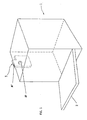
- Fig. 1 representing schematically a portion of a dishwashing machine comprising the device for the drying of crockery according to the present invention
- reference 1 indicates the wash tub of the machine as a whole, which is manufactured according to known procedures and has a front loading door 2.
- Reference 3 indicates schematically a multifunction device, which is apt for metering the water required for the regeneration of the decalcifying resins, for avoiding the back-flow of water to the mains and for condensing at least a portion of the steam produced inside the tub 1 during washing.
- This device 3 has a body of reduced overall dimensions, whose structure is conveniently obtained from plastic material, such as moulding it in two parts, which are then welded together according to known procedures (for example, through a hot blade method).
- the device 3 is fastened on the external surface of a side wall of the tub 1, and therefore it is housed in a gap available between such a wall of the tub and a wall of the cabinet of the dishwasher, or of the built-in cabinet wherein the dishwasher is housed (said elements are not represented in Fig. 1).
- the device 3 has an opening AP in correspondence with a suitable opening being present on the wall of the tub 1; the opening on the wall of the tub usually has a round shape.
- the device 3 On its top portion, the device 3 also has an opening AP' facing the external environment, i.e. in the gap previously mentioned between the tub and the cabinet.
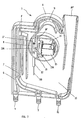
- Fig. 2 and 3 represent the multifunction device 3 comprising a device for the drying of crockery according to the present invention, which is schematically shown through a vertical section and a prospective view, respectively; it should be noticed that the view of Fig. 3 does not show a wall of the multifunction device 3, for better clarity.
- the multifunction device 3 has a hollow body, equipped with a set of inlet and outlet connectors for the water supplied from the water mains and destined to the devices contained within the machine; within the device 3, conduits and chambers are defined, through a plurality of septa or bulkheads, for the water passage and metering.
- reference 4 indicates an inlet connector for the water coming from the water mains and reference 5 an outlet connector for the same water towards a water softener of the dishwasher, not represented in the figures.
- the entry and the exit of water, through the connector 4 and connector 5 respectively, is controlled by means of solenoid valves actuated according to known procedures and appropriate times by the machine control system.
- a conduit 6 and a conduit 7 are present within the device 3.
- a so-called "air-break” or air gap device indicated as a whole with reference 8 is located between the two conduits 6 and 7.
- the air-break device 8 is of a current type and operation; it will be enough to point out, here, that its function is to hinder the water contained in the hydraulic system of the dishwasher from being sucked into the water mains, should a depression occur in the latter.
- the air-break device has an interruption 9, which can be overcome by the water supplied from the conduit 6 before entering the conduit 7, by virtue of the acquired kinetic energy.
- the remaining internal part of the device 3 practically forms a container for metering and containing the water required for the regeneration of the softening resins.
- Such a container has a chamber 10, which collects both the water supplied through a calibrated hole F being present the vertical side wall of the conduit 7 and the water which is unable to overcome the air-break 9.
- the bottom of the chamber 10 has a second outlet connector 11. Also in this instance, water flowing out from the connector 11 is controlled by a solenoid valve, not represented in the figures, which is controlled in a usual way at the appropriate time by the machine control system.
- water collected in the chamber 10 is periodically discharged through the connector 11 into a salt container of the softener device, forming a brine to be used for regeneration of the water softening resins; as said above, the procedure for water softening and regeneration of the above resins are currently known and do not need to be described in detail herein.
- the opening AP' On the upper portion of the device 3 there is the opening AP' previously mentioned; if no water is contained inside the device 3, the opening AP' puts the inside of the wash tub 1 in communication with the external environment, by means of the opening AP.
- Reference 14 indicates a closed recess, being defined next to the opening AP.
- An electromagnetic actuator 15 is located within the recess 14, where it is fastened in a known manner, e.g. with screws or clamping teeth.
- the actuator 15 has a coil provided with a movable core inside it; a pin 15A, which protrudes from the body of the actuator 15, is associated to the movable core.
- the position of the pin 15A is determined by means of a spring laying within the coil, which spring pushes the movable core to which the pin 15A is associated towards the outside of the actuator body, when the actuator is not electrically supplied.
- the pin 15A is represented by an unbroken or continuos line in the position where it will be when the actuator 15 is electrically supplied, and by a dotted line when the actuator is not powered.
- Electric supply of the electromagnetic actuator 15 is obtained through the mechanical or electronic programmer of the dishwasher, in a known manner.
- the wall 16 of the recess 14 has a through-hole for the pin 15A of the actuator 15.
- Reference 18 indicates a spraying or nebulizer device being located laterally to the wall 16 of the recess 14.
- This spraying or nebulizer device 18 comprises a nozzle 17 and a main conduit 19 hermetically connected to the nozzle 17.
- the conduit 19 consists of two tubular parts connected to each other, and precisely an upper part 19A made from elastic material, such as rubber or plastic, and a lower part 19B made from semirigid plastic material.
- the two parts 19A and 19B are hermetically connected to each other.
- the upper part 19A has a larger diameter with respect to the lower part 19B and its bottom end is substantially flared; within such a flared portion of the upper part 19A a sphere or ball is hosed, whose diameter is larger than the diameter of the lower part 19B.
- the nozzle 17 of the spraying or nebulizer device 18 and the upper part 19A of the conduit 19 are substantially located in the opening AP, sideways to the wall 16 of the recess 14, the upper part 19A extending in correspondence of the pin 15A of the actuator 15.
- the pin 15A When the pin 15A is in its rest position, i.e. with the electromagnetic actuator 15 not electrically supplied, it will cause a squashing of the upper part 19A.
- the lower part 19B is so positioned to have its bottom end within the chamber 10 of the device 3, immersed in the water contained therein during the dishwasher operation; in other words, the bottom end of the lower part 19B is located at a height being lower than the level normally reached by the regeneration water within the chamber 10.
- Reference 12 indicates a hollow sleeve integral to the body of the device 3, wherein the lower part 19B is inserted for a correct position of the spraying or nebulizer device 18.
- reference 14 A indicates the external part of the recess 14 containing the actuator 15, which protrudes over the surface of the multifunction device 3 and has such dimensions to be inserted in the opening of the wall of the tub 1 (see Fig. 1).
- Reference 17 indicates the cited nozzle of the spraying or nebulizer 18, which has a first vertical portion 17A and a second horizontal portion 17B, perpendicular to the first one and directed towards the inside of the tub 1.
- the horizontal portion 17B has sideways a hole 20 for the outlet and nebulization of a jet of liquid; the position of this hole 20 is such to have the nebulized jet of liquid directed to the inner side of the tub wall on which the multifunction device 3 is located.
- the diameter of such a hole has a clearly smaller section with respect to the section of the part 19A of the device 18; of course, the hole 20 is appropriately oriented, to hinder the liquid sprinkling coming out of it from reaching the crockery contained in the usual baskets in the tub 1.
- the device 18 is substantially obtained according to the same known technique used for manufacturing common manual sprayers or atomizers of liquid materials for house cleaning purposes (such as the washing of glass windows).
- the part 19A by virtue of its own elasticity, will go back to its initial configuration.
- a depression or vacuum is produced within the part 19A, causing the ball to move upwards, with a consequent opening of the passage between the upper part 19A and the lower part 19B, and a suction from part 19B into part 19A of a certain volume of liquid coming from the chamber 10.
- the movement upwards of the ball due to the depression produced within the part 19A is limited by means of a teeth obtained inside the upper section 19A. These teeth also have the function of maintaining the ball within the part 19A, during manufacturing the spraying or nebulizing device.
- the device 3 has appropriate means for maintaining the nozzle 17 in its correct position for avoiding that, during the actuation of the device, the part 19A is displaced sideways from the pin 15A, instead of being squashed; said means may consist for example of an appropriate striker integral to an inner surface of the device 3, as schematically indicated with R in Fig. 2.
- the set of components described above behaves like a spraying and nebulizing small pump.
- Operation of the device for drying the crockery comprising the spraying or nebulizing device 18 is also very simple and is as follows.
- the dishwasher programmer transmits electric pulses to the electromagnetic actuator 15; for each electric pulse a horizontal movement is performed by the movable core of the actuator, towards the inside of the actuator itself, with a consequent displacement of the pin 15A.
- the pin 15A releasing the upper part 19A of the conduit 19, causes this upper part to take its original configuration again, by virtue of its own elasticity.
- the spring inside the coil pushes the pin 15A against the upper part 19A of the conduit 19 of the spraying or nebulizing device 18.
- the squashing exerted by the pin 15A on the elastic material of the part 19A causes the ejection through the hole 20 of the nozzle 17 of an nebulized jet or spray of water drawn from the chamber 10 of the multifunction device 3, through the part 19B.
- the jet or spray from the hole 20 is directed onto the inner side of the wall of the tub 1 on which the multifunction device 3 is positioned; water will then be able to deposit on the wall, and flow down from the top to the bottom of the wall itself, so causing a certain cooling of the latter; obviously, repeating of the water jets or sprays will increase the cooling degree of the wall.
- the device for the drying of crockery of the type apt to induce a condensation of the steam being present within the wash tub of a dishwasher by means of the cooling of at least a tub wall, provides means for directing a liquid jet or spray on the inner surface of the wall, which are apt to cause a substantial cooling of the wall and, as a result, favour condensation on it of at least a portion of the steam contained in the tub.
- Such means for directing a liquid jet of spray to the inner surface of the wall are housed in a container for metering and/or collecting liquid being required for the operation of the dishwasher; such a container is apt to contain the liquid used by the dishwasher also for purposes other than drying the crockery.
- the liquid contained in the container is used for regenerating the resins of a water softening system and/or used for the washing of crockery.
- the means for directing a liquid jet or spray on the inner surface of the wall comprise a liquid sprayer and/or nebulizer, and an actuator for activating the sprayer and/or nebulizer.
- the sprayer and/or nebulizer comprises a nozzle connected to a conduit for the taking of the liquid to be sprayed and/or nebulized.
- the actuator in particular an electromagnetic actuator, is apt to stress an elastic portion of the conduit, so as to cause a liquid ejection from the nozzle.
- the duct has an upper part and a lower part, in particular made from elastic material and semirigid material respectively, having a tubular shape.
- the nozzle has a vertical portion, and a horizontal portion perpendicular to the vertical portion, with the horizontal portion being directed towards the inside of said tub, and being provided with a hole for the outlet and/or nebulization of a liquid jet.
- the hole is so positioned to have the nebulized jet of liquid directed on the inner side of the tub wall on which the sprayer or nebulizer is located.
- a recess is delimited for housing the actuator.
- the metering container has an opening communicating with the inside of the tub and at least the nozzle is positioned in correspondence of this opening.
- the end of the lower part of the conduit is immersed in the liquid contained in the chamber of the metering container, at least during a drying phase of the crockery as provided by an operating program of the dishwasher.
- a dishwashing machine having a wash tub and a system for drying the crockery, which device is apt to induce a condensation of the steam being present within the tub of the machine, through the cooling of at least a tub wall, comprises a device for the drying of crockery, where means are provided to direct a liquid jet or spray on the inner surface of the wall, which is apt to cause a substantial cooling of the wall and, as a result, favour condensation on it of at least a portion of the steam contained in the tub.
- this may be directed on the inner side of its rear wall.
- Another variant may concern the source of the liquid used by the sprayer 18; in other words, the device according to the present invention may use water destined to crockery washing, instead of water provided for resins regeneration; this is easy to manufacture also in the instance of multifunction devices with a plurality of separate chambers, of which one or more provide in fact for the metering of the water required to perform a wash phase.
Landscapes
- Washing And Drying Of Tableware (AREA)
Applications Claiming Priority (2)
| Application Number | Priority Date | Filing Date | Title |
|---|---|---|---|
| ITTO990064 | 1999-01-29 | ||
| IT1999TO000064 IT1307124B1 (it) | 1999-01-29 | 1999-01-29 | Dispositivo per l'asciugatura di stoviglie e macchina lavastoviglieutilizzante tale dispositivo. |
Publications (2)
| Publication Number | Publication Date |
|---|---|
| EP1023869A2 true EP1023869A2 (fr) | 2000-08-02 |
| EP1023869A3 EP1023869A3 (fr) | 2001-01-03 |
Family
ID=11417397
Family Applications (1)
| Application Number | Title | Priority Date | Filing Date |
|---|---|---|---|
| EP00200295A Withdrawn EP1023869A3 (fr) | 1999-01-29 | 2000-01-28 | Dispositif pour sécher la vaisselle et lave-vaisselle comportant un tel dispositif |
Country Status (2)
| Country | Link |
|---|---|
| EP (1) | EP1023869A3 (fr) |
| IT (1) | IT1307124B1 (fr) |
Cited By (4)
| Publication number | Priority date | Publication date | Assignee | Title |
|---|---|---|---|---|
| EP2567650A1 (fr) * | 2009-03-27 | 2013-03-13 | Electrolux Home Products Corporation N.V. | Lave-vaisselle |
| EP2586356B1 (fr) | 2011-10-28 | 2015-05-06 | BITRON S.p.A. | Dispositif d'alimentation en eau |
| US9119519B2 (en) | 2009-03-27 | 2015-09-01 | Electrolux Home Products Corporation, N.V. | Dishwasher sump member |
| EP2554092A3 (fr) * | 2011-08-03 | 2017-10-04 | LG Electronics, Inc. | Lave-vaisselle |
Citations (3)
| Publication number | Priority date | Publication date | Assignee | Title |
|---|---|---|---|---|
| FR2487186A3 (fr) * | 1980-07-25 | 1982-01-29 | Licentia Gmbh | Procede et dispositif pour la condensation des vapeurs d'eau presentes a l'interieur de la cuve d'un lave-vaisselle |
| GB2151466A (en) * | 1983-12-16 | 1985-07-24 | Bauknecht Hausgeraete | Device for condensing vapour escaping from a vent in a dish washer |
| EP0753282A1 (fr) * | 1995-07-14 | 1997-01-15 | TECNOPLASTICA PREALPINA S.p.A. | Dispositif pour refroidir et condenser la vapeur dégagée de la cuve d'un lave-vaisselle ou similaire |
-
1999
- 1999-01-29 IT IT1999TO000064 patent/IT1307124B1/it active
-
2000
- 2000-01-28 EP EP00200295A patent/EP1023869A3/fr not_active Withdrawn
Patent Citations (3)
| Publication number | Priority date | Publication date | Assignee | Title |
|---|---|---|---|---|
| FR2487186A3 (fr) * | 1980-07-25 | 1982-01-29 | Licentia Gmbh | Procede et dispositif pour la condensation des vapeurs d'eau presentes a l'interieur de la cuve d'un lave-vaisselle |
| GB2151466A (en) * | 1983-12-16 | 1985-07-24 | Bauknecht Hausgeraete | Device for condensing vapour escaping from a vent in a dish washer |
| EP0753282A1 (fr) * | 1995-07-14 | 1997-01-15 | TECNOPLASTICA PREALPINA S.p.A. | Dispositif pour refroidir et condenser la vapeur dégagée de la cuve d'un lave-vaisselle ou similaire |
Cited By (5)
| Publication number | Priority date | Publication date | Assignee | Title |
|---|---|---|---|---|
| EP2567650A1 (fr) * | 2009-03-27 | 2013-03-13 | Electrolux Home Products Corporation N.V. | Lave-vaisselle |
| US9119520B2 (en) | 2009-03-27 | 2015-09-01 | Electrolux Home Products Corporation, N.V. | Dishwasher sump member |
| US9119519B2 (en) | 2009-03-27 | 2015-09-01 | Electrolux Home Products Corporation, N.V. | Dishwasher sump member |
| EP2554092A3 (fr) * | 2011-08-03 | 2017-10-04 | LG Electronics, Inc. | Lave-vaisselle |
| EP2586356B1 (fr) | 2011-10-28 | 2015-05-06 | BITRON S.p.A. | Dispositif d'alimentation en eau |
Also Published As
| Publication number | Publication date |
|---|---|
| ITTO990064A1 (it) | 2000-07-29 |
| IT1307124B1 (it) | 2001-10-29 |
| EP1023869A3 (fr) | 2001-01-03 |
Similar Documents
| Publication | Publication Date | Title |
|---|---|---|
| KR102373181B1 (ko) | 식기 세척기 | |
| KR101871270B1 (ko) | 식기세척기 및 그의 제어방법 | |
| KR20120140680A (ko) | 식기 세척기 | |
| KR20060007259A (ko) | 식기 세척기의 상부노즐 첵 밸브 결합 구조 | |
| KR20150109944A (ko) | 식기세척기 | |
| KR20170111360A (ko) | 식기 세척기 | |
| KR101202062B1 (ko) | 스팀 발생 장치가 구비된 식기 세척기 및 제어 방법 | |
| KR102622707B1 (ko) | 식기세척기 | |
| CN106037606B (zh) | 一种洗餐盘机 | |
| WO2019086105A1 (fr) | Buse de pulvérisation de détergent en éventail | |
| EP1023869A2 (fr) | Dispositif pour sécher la vaisselle et lave-vaisselle comportant un tel dispositif | |
| US20080163906A1 (en) | Dish Washer and Display Structure Thereof | |
| KR101240787B1 (ko) | 식기 세척기 및 식기 세척기의 제어방법 | |
| KR101241458B1 (ko) | 식기 세척기의 노즐 홀더 결합 구조 | |
| US10172508B2 (en) | Dishwasher comprising a detergent dispenser | |
| KR100662156B1 (ko) | 식기 세척기의 워터 가이드 결합 구조 | |
| CN217429942U (zh) | 一种清洗机 | |
| KR101054193B1 (ko) | 식기 세척기의 에어 덕트 구조 | |
| JP3786005B2 (ja) | 食器洗い機 | |
| KR200397407Y1 (ko) | 식기 세척기의 덕트 구조 | |
| KR101208156B1 (ko) | 식기 세척기 | |
| JP2004073261A (ja) | 食器洗い機 | |
| JP3147651B2 (ja) | 食器洗い機 | |
| KR200144772Y1 (ko) | 진공식기세척기 | |
| JPH04122351A (ja) | 食器洗浄機 |
Legal Events
| Date | Code | Title | Description |
|---|---|---|---|
| PUAI | Public reference made under article 153(3) epc to a published international application that has entered the european phase |
Free format text: ORIGINAL CODE: 0009012 |
|
| AK | Designated contracting states |
Kind code of ref document: A2 Designated state(s): DE FR GB IT |
|
| AX | Request for extension of the european patent |
Free format text: AL;LT;LV;MK;RO;SI |
|
| PUAL | Search report despatched |
Free format text: ORIGINAL CODE: 0009013 |
|
| AK | Designated contracting states |
Kind code of ref document: A3 Designated state(s): AT BE CH CY DE DK ES FI FR GB GR IE IT LI LU MC NL PT SE |
|
| AX | Request for extension of the european patent |
Free format text: AL;LT;LV;MK;RO;SI |
|
| 17P | Request for examination filed |
Effective date: 20010703 |
|
| AKX | Designation fees paid |
Free format text: DE FR GB IT |
|
| 17Q | First examination report despatched |
Effective date: 20020724 |
|
| STAA | Information on the status of an ep patent application or granted ep patent |
Free format text: STATUS: THE APPLICATION IS DEEMED TO BE WITHDRAWN |
|
| 18D | Application deemed to be withdrawn |
Effective date: 20050802 |