EP1022597A2 - Mikroskop - Google Patents
Mikroskop Download PDFInfo
- Publication number
- EP1022597A2 EP1022597A2 EP00100040A EP00100040A EP1022597A2 EP 1022597 A2 EP1022597 A2 EP 1022597A2 EP 00100040 A EP00100040 A EP 00100040A EP 00100040 A EP00100040 A EP 00100040A EP 1022597 A2 EP1022597 A2 EP 1022597A2
- Authority
- EP
- European Patent Office
- Prior art keywords
- section
- stage
- specimen
- microscope
- optical axis
- Prior art date
- Legal status (The legal status is an assumption and is not a legal conclusion. Google has not performed a legal analysis and makes no representation as to the accuracy of the status listed.)
- Withdrawn
Links
Images



Classifications
-
- G—PHYSICS
- G02—OPTICS
- G02B—OPTICAL ELEMENTS, SYSTEMS OR APPARATUS
- G02B21/00—Microscopes
- G02B21/24—Base structure
Definitions
- This invention relates to a microscope and, more particularly, it relates to a microscope specifically designed to hermetically seal and protect the objective lens and the specimen when the microscope is not in use but in storage.
- a plurality of objective lenses having different respective magnifying factors are normally fitted to a rotary member normally referred to as objective turret or revolver so that a desired magnifying factor may be selected by turning the objective turret, while the stage of the microscope, which is a stationary flat member, is provided with a sliding holder for holding a specimen prepared and carried on a small glass plate for microscope observation.
- the stage of the microscope which is a stationary flat member, is provided with a sliding holder for holding a specimen or a petri dish containing a liquid specimen or liquid by turn containing a specimen.
- the microscope comprises a plurality of objective lenses fitted to an objective turret.
- the stage is designed simply for receiving a specimen on a flat area thereof.
- a specimen containing plankton is placed in a petri dish, which is by turn placed on the stage for microscopic observation.
- petri dishes are rather bulky and apt to be broken so that it is difficult to safely store them.
- the specimen is brought into focus by regulating the distance between the objective lens system and the stage.
- the object lens system is rigidly secured to the microscope main body while the stage is held by the microscope main body and made movable along the main optical axis of the optical system.
- objective lenses having different magnifying factors require different moving distances between the optical system and the specimen on the stage. Therefore, when one of the objective lenses is selected and manipulated to bring the specimen into focus, some or the remaining objective lenses may collide with the specimen or the stage. Or, there may be cases where the specimen on the stage would not come into focus at all.
- Another object of the present invention is to provide a microscope that can be easily regulated for focussing at the time of assembly and also at the time of using it for microscope observation.
- Still another object of the present invention is to provide a microscope whose objective lenses and stage are protected against exposure to the atmosphere when it is not in use and also prevented from collecting fine pieces of dust and being adversely affected by moisture in the atmosphere.
- Still another object of the present invention is to provide a microscope with which a specimen of liquid that contains plankton can be placed on the stage for microscopic observation without using a petri dish.
- a further object of the present invention is to provide a microscope with which objective lenses of different magnifying factors can be efficiently and conveniently used without the risk of colliding with the stage and that of being unable to bring the specimen into focus to a certain extent.
- a microscope comprising a support section adapted to support a viewing section and an objective lens section and slidably support a stage section and a lighting section, characterized in that said objective lens section including a plurality of objective lenses having different magnifying factors and arranged linearly in a direction perpendicular to said support section and said objective lenses are contained in a downwardly directed housing while said stage section is contained in an upwardly directed housing so that a hermetically sealed housing can be formed of said downwardly directed housing and said upwardly directed housing by driving said stage section to slide.
- a microscope comprising a plurality of objective lenses adapted to be selectively placed on the optical axis of the optical system of the microscope and a stage for carrying a specimen, characterized in that said stage includes a stationary stage section having sliding guide grooves running perpendicular relative to the main optical axis of the optical system and a sliding stage plate section having sliding guide ridges, said sliding stage plate section having a plurality of specimen receivers with specimen receiving planes disposed at different positions relative to the main optical axis.
- a microscope stage characterized by comprising a stationary stage section having sliding guide grooves running perpendicular relative to the main optical axis of the optical system and a sliding stage plate section having sliding guide ridges, said sliding stage plate section having a plurality of specimen receivers with specimen receiving planes disposed at different positions relative to the main optical axis.
- said stage section has recesses with transparent members arranged at the bottom thereof.
- said stage section is interchangeable.
- said viewing section is of the projection type.
- said viewing section has two screens including a front screen and a rear screen.
- said viewing section includes an inclined reflection mirror adapted to rotate around the optical axis of said objective lenses and project an image of the specimen onto one of said screens.
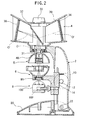
- microscope 1 comprises a support member 2 for supporting a viewing section 4 and an objective lens section 5. Additionally, the support member 2 slidably supports a stage section 6 for carrying a specimen and a lighting section 8.
- the support section 2 is provided at a lateral side thereof with a focussing knob 10. As the knob 10 is rotated, both the stage section 6 and the lighting section 8 are moved up and down by way of a rack 14 held in engagement with a pinion 12, which pinion 12 is integral with the focussing knob 10.
- the support section 2 is swingably fitted to a base 20 by means of a pin 22 so that the support section 2 may be held to an upright position or an inclined position.
- the viewing section 4 shown in FIGS. 1 and 2 is of the projection type, it is interchangeable and may be replaced by one or two eye pieces (not shown).
- the projection type viewing section 4 comprises a housing 30 that contains therein an inclined mirror 32 is arranged on the optical axis O of projection lens 31.
- the mirror 32 can be rotated by means of a viewing control knob 33.
- An observer screen 34 and an assistant screen 36 are made of frosted glass and arranged respectively on the two reflected optical axes O' of the inclined mirror 32.
- the objective lens section 5 comprises an objective lens housing 40 having a semispherical profile and containing the other components of the objective lens section 5 including an objective lens 42 with a magnifying factor of 15, an objective lens 44 with a magnifying factor of 10 and an objective lens 46 with a magnifying factor of 40, which are housed in and supported by a lens holder 48 that is slidable in a direction perpendicular to the optical axis O.
- the objective lens section 5 is guided by a pair of guide rails 54, 58 to move in a direction perpendicular to the optical axis O so that the lens having a desired magnifying factor may be selected for use by moving the lens holder 48 to slide on the guide rails 54, 56, which are secured to the top of the support section 2 by means of screws 50,52.
- the guide rails 54, 56 respectively have rail ridges 60, 60, resilient arms 64, 64 and click projections 68, 70 as integral parts thereof.
- the click projections 68, 70 click-fit with respective clock notches 74, 76 of the lens holder 48 so that selected one of the objective lenses 42, 44, 46 can be held on the optical axis O with little holding effort.
- the stage section 6 comprises a substantially semispherical stage housing 80 for containing the other components of the stage section 6.
- the part of the stage section 6 that contains a specimen is interchangeable. Referring to FIGS. 5 through 8, it has a flat surface 210, which is a stationary stage member, and a slit 220 extending to the side opposite to the support section 2 and adapted to removable receive a specimen holder 222 like a drawer.
- the specimen holder 222 is provided at upper positions on the lateral walls thereof with respective horizontal sliding guide ridges 230 extending in parallel with the top and bottom surfaces.
- the specimen holder 222 is also provided at the oppositely disposed rounded ends thereof with respective circular through holes 240, 242 that are concentric with the respective rounded ends.
- a circular piece of polished plane glass 250 is water-tightly fitted to the top of the circular through hole 240, while another circular piece of polished plane glass 250 is water-tightly fitted to the bottom of the circular through hole 242.
- These two circular pieces of plane polished glass operate as so many stages for carrying respective specimens.
- the specimen holder 222 is additionally provided with a pair of semicircular recesses 260, 262 that are cut from the side of the circular piece of polished plane glass 252 at positions between the two circular through holes 240, 242 and open at the respective lateral sides that are parallel to the line connecting the centers of the two circular through holes 240, 242 as most clearly seen from FIG. 7 showing the specimen holder turned upside down relative to FIG. 5.
- the slit 220 is provided on the lateral walls thereof with sliding guide grooves 264 for receiving the respective sliding guide ridges 230.
- the flat surface 210 becomes flush with the upper surface of the specimen holder 222 so that the circular piece of polished glass 252 operating as bottom of the circular through hole 242 for receiving a liquid specimen is located significantly below the flat surface 210. Then, the specimen may not be in focus if the objective lenses 42, 44, 46 are brought down to the lowest position by means of the focussing knob 10.
- the specimen holder 222 of FIG. 5 is turned upside down to make it take a posture as shown in FIG. 7 and inserted into the slit 220 to make the circular piece of polished plane glass 252 flush with the flat surface 210, the circular piece of polished glass 250 operating to block the circular through hole 240 for receiving a specimen is located significantly above the position of FIG. 6. Then, the specimen in the specimen holder 222 that is not in focus with the posture of FIG. 6 may now be in focus.
- stage section 6 having a configuration as described above, it is now possible to observe water fleas, plankton and brine shrimps that are alive and moving through the microscope. Similarly, small creatures such as ants, mosquitoes, ant cows and mysis can be observed through the microscope while they are alive and moving. Additionally, small plants such as diatoms, pollen, spores of ferns, seeds, mineral sand, iron sand, sugar and salt can be effectively and clearly observed through the microscope.
- Reflection lighting or lighting using a lamp may feasibly be used for the lighting section 8.
- Light may be emitted upwardly from a lamp (not shown) contained in a lamp housing 100 in a manner as shown in FIG. 2 to irradiate the stage section 6.
- Reflection mirror 102 may be used to reflect ambient light toward the stage section 6 when it is turned by about 180 degrees from the posture shown in FIG. 2.
- the objective lens section 5 is positionally so regulated as to make the central objective lens 44 to be located on the optical axis O and the specimen holder 222 is inserted into the slit 220 to make it take a posture as shown in FIG. 5 or FIG. 7. Subsequently, the focussing knob 10 is rotated to raise the stage section 6 and the lighting section 8 to put the objective lens housing 40 and the stage housing 80 together and form a ball, when the two housings are hermetically sealed to protect the objective lenses 42, 44, 46, the stage section 6 and other related components.
- a plurality of objective lenses with different magnifying factors are fitted to a lens holder that is reciprocally movable in a direction perpendicular to the main optical axis of the optical system in the above described embodiment of microscope according to the invention
- a plurality of objective lenses with different magnifying factors may be fitted to a turret or a revolver in another embodiment.
- FIG. 9 shows another possible configuration of specimen holder that can be used for the purpose of the invention.
- the specimen holder 300 of FIG. 9 also has rounded opposite ends and is adapted to be received into the stage section 6 like a drawer. It is also provided at upper positions on the lateral walls thereof with respective horizontal sliding guide ridges 302 extending in parallel with the top and bottom surfaces.
- the specimen holder 300 is further provided at the oppositely disposed rounded ends thereof with respective circular through holes 310, 320 that are concentric with the respective rounded ends.
- a circular piece of polished plane glass 312 is water-tightly fitted to the bottom of the circular through hole 310 and another circular piece of polished plane glass 322 is also water-tightly fitted to the bottom of the circular through hole 320. These two circular pieces of plane polished glass operate as so many stages for carrying respective specimens.
- the specimen holder 300 can shifts the level of the stage to be used when it is turned around and inserted into the stage section 6 without being turned upside down.
- the specimen holder may alternatively be prepared in such a way that the transparent members for blocking the circular threshold holes are made of acryl or, still alternatively, the entire specimen holder may be made of acryl.
- the objective lenses with different magnifying factors can be effectively utilized without causing them collide with the specimen holding stage and the microscope can prevent the specimen from going out of focus to a considerable extent.
Landscapes
- Physics & Mathematics (AREA)
- Chemical & Material Sciences (AREA)
- Analytical Chemistry (AREA)
- General Physics & Mathematics (AREA)
- Optics & Photonics (AREA)
- Microscoopes, Condenser (AREA)
Applications Claiming Priority (4)
| Application Number | Priority Date | Filing Date | Title |
|---|---|---|---|
| JP1030299 | 1999-01-19 | ||
| JP11010302A JP2000206413A (ja) | 1999-01-19 | 1999-01-19 | 顕微鏡 |
| JP5079299 | 1999-02-26 | ||
| JP11050792A JP2000249923A (ja) | 1999-02-26 | 1999-02-26 | 顕微鏡 |
Publications (2)
| Publication Number | Publication Date |
|---|---|
| EP1022597A2 true EP1022597A2 (de) | 2000-07-26 |
| EP1022597A3 EP1022597A3 (de) | 2001-04-04 |
Family
ID=26345565
Family Applications (1)
| Application Number | Title | Priority Date | Filing Date |
|---|---|---|---|
| EP00100040A Withdrawn EP1022597A3 (de) | 1999-01-19 | 2000-01-04 | Mikroskop |
Country Status (3)
| Country | Link |
|---|---|
| US (1) | US6252704B1 (de) |
| EP (1) | EP1022597A3 (de) |
| CA (1) | CA2296139A1 (de) |
Cited By (1)
| Publication number | Priority date | Publication date | Assignee | Title |
|---|---|---|---|---|
| EP1710610A3 (de) * | 2005-04-08 | 2006-11-02 | Olympus Corporation | Mikroskop mit einer Steuereinrichtung zur Steuerung der Bewegungsgeschwindigkeit des Probentisches in Abhängigkeit von der Vergrösserung des ausgewählten Objektives |
Families Citing this family (3)
| Publication number | Priority date | Publication date | Assignee | Title |
|---|---|---|---|---|
| CA2243090A1 (en) * | 1998-07-10 | 2000-01-10 | Timothy M. Richardson | Inverted darkfield contrast microscope and method |
| KR20080033027A (ko) * | 2006-10-12 | 2008-04-16 | 최해용 | 교육용 실체 현미 영상 장치 |
| CN115342918B (zh) * | 2021-05-14 | 2024-12-06 | 刘承贤 | 可携式观察微流道用环型萤光光路系统及其运作方法 |
Family Cites Families (11)
| Publication number | Priority date | Publication date | Assignee | Title |
|---|---|---|---|---|
| US3259012A (en) * | 1960-09-12 | 1966-07-05 | Inv S Finance Corp | Microscope having bridge type support arm for body tube and focusing mechanism |
| US4427332A (en) * | 1982-02-26 | 1984-01-24 | Nanometrics, Incorporated | Integrated circuit wafer transport mechanism |
| FR2532065A1 (fr) * | 1982-08-20 | 1984-02-24 | Crismatec | Ecran anti-pollution pour microscope et binoculaires |
| JPS62269924A (ja) * | 1986-05-06 | 1987-11-24 | Suraidetsukusu Kk | 顕微鏡 |
| DE3802535A1 (de) * | 1987-05-21 | 1989-02-23 | Sattler Hans Eberhard | Vorrichtung zur betrachtung insbesondere von rohedelsteinen in einer immersionsfluessigkeit |
| DE3731120A1 (de) * | 1987-09-16 | 1989-03-30 | Leitz Ernst Gmbh | Universeller objekthalter fuer mikroskope |
| DE3918990A1 (de) * | 1989-06-10 | 1990-12-13 | Zeiss Carl Fa | Mikroskop mit bildhelligkeitsabgleich |
| US5315344A (en) * | 1991-03-29 | 1994-05-24 | Polaroid Corporation | Microscope camera |
| US5682264A (en) * | 1993-03-01 | 1997-10-28 | Microtek Medical, Inc. | Universal microscope drape |
| US5835265A (en) * | 1996-07-18 | 1998-11-10 | Computed Anatomy Incorporated | Large numerical aperture imaging device |
| US5853363A (en) * | 1997-07-28 | 1998-12-29 | Deka Medical, Inc. | Surgical microscope operating drape and methods of operation and manufacture thereof |
-
2000
- 2000-01-04 EP EP00100040A patent/EP1022597A3/de not_active Withdrawn
- 2000-01-14 CA CA002296139A patent/CA2296139A1/en not_active Abandoned
- 2000-01-19 US US09/487,350 patent/US6252704B1/en not_active Expired - Fee Related
Cited By (2)
| Publication number | Priority date | Publication date | Assignee | Title |
|---|---|---|---|---|
| EP1710610A3 (de) * | 2005-04-08 | 2006-11-02 | Olympus Corporation | Mikroskop mit einer Steuereinrichtung zur Steuerung der Bewegungsgeschwindigkeit des Probentisches in Abhängigkeit von der Vergrösserung des ausgewählten Objektives |
| US7542202B2 (en) | 2005-04-08 | 2009-06-02 | Olympus Corporation | Microscope and a controlling method thereof |
Also Published As
| Publication number | Publication date |
|---|---|
| EP1022597A3 (de) | 2001-04-04 |
| US6252704B1 (en) | 2001-06-26 |
| CA2296139A1 (en) | 2000-07-19 |
Similar Documents
| Publication | Publication Date | Title |
|---|---|---|
| JP4354446B2 (ja) | 顕微鏡ステージ及び顕微鏡観察用ユニット | |
| US4836667A (en) | Microscope | |
| US4210384A (en) | Inverted-design optical microscope | |
| US20210396983A1 (en) | Kit for microscopic observation associable with an image acquisition device | |
| US4737016A (en) | Portable field microscope | |
| JPH0611651A (ja) | 顕微鏡 | |
| US6252704B1 (en) | Microscope | |
| US6137628A (en) | Stereomicroscope having a specimen changer | |
| CN111492295A (zh) | 用于对样本成像的显微镜和用于这种显微镜的样本保持器 | |
| CN220357316U (zh) | 一种正倒置观察显微镜 | |
| EP0245089B1 (de) | Mikroskop | |
| US3868171A (en) | Surgical microscope | |
| US4337991A (en) | Light microscope with a plurality of slideways | |
| JP7602527B2 (ja) | 生細胞又は生細胞のセットを観察するための装置 | |
| JP2000206413A (ja) | 顕微鏡 | |
| US5757542A (en) | Polarizing accessory system for microscopes | |
| JP4106139B2 (ja) | 高解像マクロスコープ | |
| CN1261682A (zh) | 显微镜 | |
| US5969856A (en) | Center masking add-on illuminator | |
| JP2000019411A (ja) | 実体顕微鏡の照明装置 | |
| JP2000249923A (ja) | 顕微鏡 | |
| JP3375301B2 (ja) | 顕微鏡 | |
| US7835075B2 (en) | Replacement device for microscopes | |
| US6404565B2 (en) | Magnifying scope with specimen holders | |
| HK1030057A (zh) | 显微镜 |
Legal Events
| Date | Code | Title | Description |
|---|---|---|---|
| PUAI | Public reference made under article 153(3) epc to a published international application that has entered the european phase |
Free format text: ORIGINAL CODE: 0009012 |
|
| AK | Designated contracting states |
Kind code of ref document: A2 Designated state(s): DE FR GB IT |
|
| AX | Request for extension of the european patent |
Free format text: AL;LT;LV;MK;RO;SI |
|
| PUAL | Search report despatched |
Free format text: ORIGINAL CODE: 0009013 |
|
| RIC1 | Information provided on ipc code assigned before grant |
Free format text: 7G 02B 21/24 A, 7G 02B 21/26 B |
|
| AK | Designated contracting states |
Kind code of ref document: A3 Designated state(s): AT BE CH CY DE DK ES FI FR GB GR IE IT LI LU MC NL PT SE |
|
| AX | Request for extension of the european patent |
Free format text: AL;LT;LV;MK;RO;SI |
|
| 17P | Request for examination filed |
Effective date: 20011004 |
|
| AKX | Designation fees paid |
Free format text: DE FR GB IT |
|
| STAA | Information on the status of an ep patent application or granted ep patent |
Free format text: STATUS: THE APPLICATION HAS BEEN WITHDRAWN |
|
| 18W | Application withdrawn |
Withdrawal date: 20020927 |