EP1022470A1 - Radialgebläse - Google Patents
Radialgebläse Download PDFInfo
- Publication number
- EP1022470A1 EP1022470A1 EP99100937A EP99100937A EP1022470A1 EP 1022470 A1 EP1022470 A1 EP 1022470A1 EP 99100937 A EP99100937 A EP 99100937A EP 99100937 A EP99100937 A EP 99100937A EP 1022470 A1 EP1022470 A1 EP 1022470A1
- Authority
- EP
- European Patent Office
- Prior art keywords
- wall
- impeller
- radial fan
- fan according
- suction
- Prior art date
- Legal status (The legal status is an assumption and is not a legal conclusion. Google has not performed a legal analysis and makes no representation as to the accuracy of the status listed.)
- Granted
Links
- 238000005192 partition Methods 0.000 claims description 18
- 230000002093 peripheral effect Effects 0.000 claims description 13
- 230000003068 static effect Effects 0.000 abstract description 2
- 230000006698 induction Effects 0.000 abstract 4
- 230000000694 effects Effects 0.000 description 6
- 238000005516 engineering process Methods 0.000 description 3
- 230000004048 modification Effects 0.000 description 3
- 238000012986 modification Methods 0.000 description 3
- 238000007789 sealing Methods 0.000 description 3
- 230000001133 acceleration Effects 0.000 description 2
- 210000003734 kidney Anatomy 0.000 description 2
- 230000009467 reduction Effects 0.000 description 2
- 230000009471 action Effects 0.000 description 1
- 230000008859 change Effects 0.000 description 1
- 230000006835 compression Effects 0.000 description 1
- 238000007906 compression Methods 0.000 description 1
- 230000006735 deficit Effects 0.000 description 1
- 238000011161 development Methods 0.000 description 1
- 230000018109 developmental process Effects 0.000 description 1
- 230000008030 elimination Effects 0.000 description 1
- 238000003379 elimination reaction Methods 0.000 description 1
- 239000012530 fluid Substances 0.000 description 1
- 238000000034 method Methods 0.000 description 1
- 230000001105 regulatory effect Effects 0.000 description 1
- 230000006641 stabilisation Effects 0.000 description 1
- 238000011105 stabilization Methods 0.000 description 1
- 230000000087 stabilizing effect Effects 0.000 description 1
- 230000007704 transition Effects 0.000 description 1
Images


Classifications
-
- F—MECHANICAL ENGINEERING; LIGHTING; HEATING; WEAPONS; BLASTING
- F04—POSITIVE - DISPLACEMENT MACHINES FOR LIQUIDS; PUMPS FOR LIQUIDS OR ELASTIC FLUIDS
- F04D—NON-POSITIVE-DISPLACEMENT PUMPS
- F04D29/00—Details, component parts, or accessories
- F04D29/40—Casings; Connections of working fluid
- F04D29/42—Casings; Connections of working fluid for radial or helico-centrifugal pumps
- F04D29/4206—Casings; Connections of working fluid for radial or helico-centrifugal pumps especially adapted for elastic fluid pumps
- F04D29/4213—Casings; Connections of working fluid for radial or helico-centrifugal pumps especially adapted for elastic fluid pumps suction ports
-
- F—MECHANICAL ENGINEERING; LIGHTING; HEATING; WEAPONS; BLASTING
- F04—POSITIVE - DISPLACEMENT MACHINES FOR LIQUIDS; PUMPS FOR LIQUIDS OR ELASTIC FLUIDS
- F04D—NON-POSITIVE-DISPLACEMENT PUMPS
- F04D17/00—Radial-flow pumps, e.g. centrifugal pumps; Helico-centrifugal pumps
- F04D17/02—Radial-flow pumps, e.g. centrifugal pumps; Helico-centrifugal pumps having non-centrifugal stages, e.g. centripetal
- F04D17/04—Radial-flow pumps, e.g. centrifugal pumps; Helico-centrifugal pumps having non-centrifugal stages, e.g. centripetal of transverse-flow type
-
- F—MECHANICAL ENGINEERING; LIGHTING; HEATING; WEAPONS; BLASTING
- F04—POSITIVE - DISPLACEMENT MACHINES FOR LIQUIDS; PUMPS FOR LIQUIDS OR ELASTIC FLUIDS
- F04D—NON-POSITIVE-DISPLACEMENT PUMPS
- F04D17/00—Radial-flow pumps, e.g. centrifugal pumps; Helico-centrifugal pumps
- F04D17/08—Centrifugal pumps
- F04D17/16—Centrifugal pumps for displacing without appreciable compression
-
- F—MECHANICAL ENGINEERING; LIGHTING; HEATING; WEAPONS; BLASTING
- F04—POSITIVE - DISPLACEMENT MACHINES FOR LIQUIDS; PUMPS FOR LIQUIDS OR ELASTIC FLUIDS
- F04D—NON-POSITIVE-DISPLACEMENT PUMPS
- F04D25/00—Pumping installations or systems
- F04D25/16—Combinations of two or more pumps ; Producing two or more separate gas flows
- F04D25/166—Combinations of two or more pumps ; Producing two or more separate gas flows using fans
Definitions
- the invention relates to a radial fan with a pot-like Impeller with a blade ring on its circumference is provided with a housing accommodating the impeller, starting from a part-circle-curved, running directly along the blade ring Circumferential wall area like a screw in the direction of rotation of the Impeller expanded radially to one outlet and two the side walls covering axial end faces of the impeller has, one on one of the side walls arranged partition engages in the pot-like impeller and its interior into a first and a second Divided suction space, and wherein the first suction space Intake opening is assigned and the second suction chamber circumferential wall area running directly along the blade ring is facing.
- An object of the present invention is now to show further measures through which the achievable Working pressure and efficiency also increased can be.
- This object is achieved in that the Intake opening with a extending into the first suction space in the manner of a delivery injector as a ring wall, Partial wall or spoiler wall trained Injector wall is provided.
- the injector wall is expediently on the inside attached to the corresponding side wall of the housing or molded or integrally connected to this.
- the intake opening is to improve the flow on the outside of the corresponding side wall the housing by a bead-like flow guide ring surround.
- the streamlines of the intake airflow are thereby harmonizing and stabilizing what also an increase in efficiency or reduction of losses leads.
- the suction opening also narrows to the inside, so that the airflow in addition is compressed and accelerated.
- the suction opening can be round, but triangular, teardrop-shaped or kidney-shaped suction openings proven to be even cheaper. These extend then preferably up to the corner area of the first Suction chamber in the direction of flow through the blade ring of the impeller and the partition is formed.
- the suction opening can be varied. There is a small one Intake opening to achieve a steeper pressure-volume characteristic or a large suction opening to achieve this a flattened pressure-volume characteristic is provided. In all of these cases, the injector wall improves the efficiency.
- Another advantageous measure to optimize the Pressure-volume characteristics, the efficiency and the Blower performance is that inside the case outside of the impeller between the two side walls at least an adjustable flow guide element is arranged is, in particular, wing-shaped and preferably adjustable by means of an adjusting device is.
- this flow control element As a location for this flow control element the border area between which the Blower leaving power flow and the radial in the second suction chamber of the impeller entering second Working current, this flow control element for division is formed between these streams.
- this is wing-like Flow guide element as a whole or in Direction of flow seen rear area around an axis pivoted.
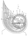
- a radial fan is a pot-like impeller 10 rotatably mounted in a screw-like housing 11.
- the impeller 10 consists of a circular disc Bottom 12, the center of a hub 13 for connection with the drive axle of a not shown for simplicity Drive motor owns.
- On the radially outer peripheral area of the floor 12 rises perpendicular to the plane of the bottom 12 a plurality of blades 14, one Form blade ring 15.
- the blades 14 are on one End at the bottom 12 and at the other end with a retaining ring 16 connected by means of bent retaining tabs 17.
- the Blades 14 are curved and opposite to the radial direction inclined by an angle, which is preferably 26 - 29 °.
- the housing 11 consists of a helically shaped Circumferential wall 18, with a curved part-circle Circumferential wall area 19 directly with a very small Gap of less than 1 mm along the blade ring 15 extends, in the exemplary embodiment over an angle of approx. 110 °. However, this angle can vary and between 60 ° and 150 °.
- This peripheral wall area 19 can provided with a large number of parallel groove-like depressions be parallel or oblique or curved extend to the axis of rotation of the impeller 10 and opposite Blade ring 15 of the impeller 10 a seal according to Art a labyrinth seal to increase the blower output and work pressure.
- the end of the peripheral wall region 19 widens Circumferential wall 18 while increasing the radial distance to the axis of rotation of the impeller 10 to a blower outlet 21 out.
- the peripheral wall 18 thus forms in this Area a spiral extension angle towards the impeller 10, wherein the peripheral wall 18 in the transition area experiences a slight kink.
- One against the direction of curvature of the peripheral wall region 19 curved end region 22 of the Circumferential wall 18 connects the circumferential wall region 19 with the fan outlet 21.
- the peripheral wall 18 forms together with two the open sides of the peripheral wall 18th covering side walls 23, 24, the housing 11 cover these side walls 23, 24 also the axial End faces of the impeller 10.
- Impeller 10 to the two side walls 23, 24 serve labyrinth seals 25, such as in state of the art at the beginning.
- the bottom 12 of the impeller 10 is the shape of the adjacent side wall 23 adapted, the in Fig. 2 recognizable, multi-angled cross-sectional shape the bottom 12 causes an additional seal.
- a partition extends from the side wall 24 26 and divided into the interior of the pot-like impeller 10 whose interior into a first suction chamber V1 and one second suction chamber V2, which faces the peripheral wall region 19 is.
- This partition 26 can according to the beginning indicated prior art from the side wall 24 extend obliquely to the bottom 12 of the impeller 10, wherein in principle also an arrangement parallel to the axis of rotation the impeller 10 is possible.
- the side wall 24 has an air intake opening 28 provided, which opens into the first suction chamber V1.
- These kidney or teardrop-shaped air intake opening 28 extends from the middle area of the first suction chamber V1 their tapered end to the corner of this first Suction chamber V1 into that of the partition 26 and the Blade ring 15 is formed on the outflow end region becomes.
- the working current A1 which will be discussed in more detail later flows into the interior of the work area V1 this air intake opening 28 past.
- An injector wall 20 encompasses the rear in the flow direction Area of the air intake opening 28 in the form of a partial ring or a scoop and extends obliquely to the working current A1 directed into the interior of the suction space V1.
- the air intake 28 itself is also slanted accordingly Interior of the suction chamber V1 directed.
- Three flow guiding elements designed as flow islands 29 - 31 in the interior of the housing 11 are as Connecting elements between the two side walls 23, 24 trained and serve for elimination of turbulent flow components (vortex zones) and to Establishing a flow profile that is as homogeneous as possible. Turbulent Currents would produce the desired flow hinder and cause increased noise.
- the adjustable flow guide element 31 is wing-shaped and in the border area between the directed to the blower outlet 21 and there the blower leaving power flow and into the suction chamber V2 backflow working stream 2 (A2) arranged.
- the Flow guide element 31 consists of a front, non-moving area 32 and a rear, pivotable area 33, with the Swiveling an adjusting device, not shown is provided, through which the pivotable region 33 actuated or set from outside the housing can be. In a modification of the flow guide element shown 31 this can also be made in one piece and be pivotable as a whole. In addition, you can the other flow guide elements 29 and 30 and any further flow guide elements designed to be pivotable his.
- Impeller 10 in the area of the first suction chamber V1 as a radial fan. Outside air is drawn in through the air intake opening 28 in sucked the first suction chamber V1 and over the circumferential area of the first suction chamber V1 radially through the blade ring 15 accelerated to the outside. This accelerated air flow divides outside into a working current A1 and one Working current A2 on.
- the working current A1 comes in again the first suction chamber V1 and is due to the radial fan action accelerated again towards the outside, whereby a substantial part of this work flow on the opposite End of the first suction chamber V1 in the by the Spiral expansion angle formed spiral expansion area reached.
- this working flow A1 passes through the air intake opening 28. There is a redirection and acceleration on the spoiler-like injector wall 20. This creates a suction effect based on the jet pump principle, reinforced by the air from the outside the air intake opening 28 is sucked in and accelerated, which leads to the desired increase in efficiency, the Working pressure and the achievable blower performance leads.
- the impeller 10 is on in the area of the second suction chamber V2 its two axial end faces through the side walls 23, 24 tightly sealed. Forms towards the interior the partition 26 has a tight seal, and on which the Partition opposite peripheral edge region 19 takes place also by small column or if necessary Labyrinth sealing system sealing the impeller 10. This therefore works in the area of the second suction chamber V2 exclusively as a cross flow fan, which is the working flow A2 sucks in the area of the blower outlet 21, compressed and in the one limited by the spiral expansion angle Blow out spiral extension area or diffuser.
- the radial fan thus works in part as a two-stage Blower with a formed by the first suction chamber V1 as a radial fan stage and one by the second suction chamber V2 formed as a cross-flow fan working level.
- the adjustable flow control element 31 can be the ratio between the working current A2 and the power flow to the fan outlet 21 L can be set.
- an injector wall 34 in contrast to the injector wall 20 in one piece with the correspondingly modified Side wall 35 connected. Same or equivalent Components are otherwise with the same reference numerals provided and not described again.
- this air intake opening 36 is on the outside of a bead-like flow guide ring 37 surrounded, also in one piece on the side wall 35 is molded and for harmonization and stabilization the streamlines of the intake air flow.
- the spoiler-like surrounds Injector wall 34 like a ring, the air intake opening 28 or 36 on opposite to the flow direction End region of this air intake opening 28 or 36.
- this could also be a tubular or Kick injector wall.
- FIG. 4 is an approximation centrally arranged round air intake opening 38 with a corresponding injector wall 42, in Fig. 5 in substantially triangular air intake opening 39 with a corresponding injector wall 43 on the air outlet side End region of the suction chamber V1, in Fig. 6 a drip or kidney-shaped air intake opening 40 with a corresponding Injector wall 44 and a modified one in FIG. 7 drop-shaped or kidney-shaped air intake opening 41 with a corresponding injector wall 45 shown. It is 6 instead of the linear partition 26 of the others Embodiments of an S-shaped curved partition 46 provided at the curvature of the air intake opening 40 in is adapted to a certain extent.
- the P / V characteristics of the Blower can be set or preselected.
- Fig. 9 the corresponding P / V characteristics a to c are shown, the air intake openings 38 to 41 in this Order are assigned.
- the usual P / V characteristics are given by the pressure figure ⁇ the delivery number ⁇ again.
- the digit ⁇ sets the delivery pressure ⁇ p in relation to the dynamic Pressure that the fluid has when its speed equal to the peripheral speed of the impeller is.
- the delivery number ⁇ sets the mean flow rate based on the outside diameter of the wheel Impeller in relation to the peripheral speed of the Impeller. From Fig.
- FIG. 6 The arrangement according to FIG. 6 is somewhat expanded in FIG. 8 shown.
- one is parallel to one Rotation axis of the impeller 10 arranged pivot axis 47 pivotable swivel plate 48 is provided, through which the Suction opening 40 is more or less coverable.
- the air intake cross section can be changed, so that in principle the characteristic curves or Characteristics can be set as required can.
- a swivel plate 48 can of course other means of covering occur through which the Cross section of the air intake opening 40 or the air intake openings of the other embodiments changed can be.
- a lockable one is suitable, for example Adjustment knob or rotary lever.
- a Motorized adjustment device may be provided, for example in the event that the fan characteristic over a control device is controlled or regulated. in the The simplest case can be such an adjustment device also from an engagement recess for attaching a Screwdriver or the like consist.
Landscapes
- Engineering & Computer Science (AREA)
- Mechanical Engineering (AREA)
- General Engineering & Computer Science (AREA)
- Structures Of Non-Positive Displacement Pumps (AREA)
- Jet Pumps And Other Pumps (AREA)
Abstract
Description
- Fig. 1
- eine Seitenansicht eines Radialgebläses als Ausführungsbeispiel der Erfindung, bei dem die mit der Trennwand versehene Seitenwandung abgenommen, jedoch die Trennwand und die Ansaugöffnung dargestellt sind,
- Fig. 2
- eine Teilschnittdarstellung des in Fig. 1 dargestellten Ausführungsbeispiels durch die Ansaugöffnung und parallel zur Trennwand,
- Fig. 3
- eine entsprechende Schnittdarstellung mit einer weiteren Ausführungsform der Injektorwandung,
- Fig. 4
- einen Teilbereich des Laufrads mit runder Ansaugöffnung in der Draufsicht,
- Fig. 5
- eine entsprechende Darstellung mit im wesentlichen dreieckförmiger Ansaugöffnung,
- Fig. 6
- eine entsprechende Darstellung mit tropfen- oder nierenförmiger Ansaugöffnung und einer gekrümmten Trennwand,
- Fig. 7
- eine entsprechende Darstellung mit einer alternativ ausgestalteten nieren- oder tropfenförmigen Ansaugöffnung,
- Fig. 8
- eine gegenüber Fig. 6 erweiterte Darstellung mit einer Schwenkscheibe zur Veränderung der Ansaugöffnung und
- Fig. 9
- verschiedene P/V-Charakteristiken zu den Ausführungen gemäß den Fig. 4 bis 7.
Claims (13)
- Radialgebläse mit einem topfartigen Laufrad (10), das an seinem Umfang mit einem Schaufelkranz (15) versehen ist, mit einem das Laufrad (10) aufnehmenden Gehäuse (11), das sich ausgehend von einem teilkreisartig gekrümmten, direkt entlang des Schaufelkranzes (15) verlaufenden Umfangswandbereich (19) schneckenartig in Drehrichtung des Laufrads (10) radial zu einem Auslaß (21) erweitert und zwei die axialen Stirnseiten des Laufrads (10) abdeckende Seitenwandungen (23, 24; 35) besitzt, wobei eine an einer der Seitenwandungen (24; 35) angeordnete Trennwand (26; 46) in das topfartige Laufrad (10) eingreift und dessen Innenraum in einen ersten und einen zweiten Saugraum (V1, V2) unterteilt, und wobei dem ersten Saugraum (V1) eine Ansaugöffnung (28; 36; 38-41) zugeordnet ist und der zweite Saugraum (V2) dem direkt entlang des Schaufelkranzes (15) verlaufenden Umfangswandbereich (19) zugewandt ist, dadurch gekennzeichnet, daß die Ansaugöffnung (28; 36; 38-41) mit einer sich in den ersten Saugraum (V1) erstreckenden, nach Art eines Förderinjektors als Ringwandung, Teilringwandung oder Spoilerwandung ausgebildeten Injektorwandung (20; 34; 42-45) versehen ist.
- Radialgebläse nach Anspruch 1, dadurch gekennzeichnet, daß die Ansaugöffnung (28; 36; 38-41) und/oder die Injektorwandung (20; 34; 42-45) schräg zur Strömungsrichtung hin im Inneren des ersten Saugraums (V1) gerichtet ist.
- Radialgebläse nach Anspruch 1 oder 2, dadurch gekennzeichnet, daß sich die spoilerartige Injektorwandung (20; 34; 42-45) nur im in Strömungsrichtung gesehen hinteren Bereich der Ansaugöffnung (28; 36; 38-41) entlang dieser erstreckt.
- Radialgebläse nach einem der vorhergehenden Ansprüche, dadurch gekennzeichnet, daß die Injektorwandung (20; 34; 42-45) an der Innenseite der entsprechenden Seitenwandung (24; 35) des Gehäuses (11) angebracht oder angeformt oder einstückig mit dieser verbunden ist.
- Radialgebläse nach einem der vorhergehenden Ansprüche, dadurch gekennzeichnet, daß die Ansaugöffnung (36) an der Außenseite der entsprechenden Seitenwandung (35) des Gehäuses (11) von einem wulstartigen Strömungsführungsring (37) umgeben ist.
- Radialgebläse nach einem der vorhergehenden Ansprüche, dadurch gekennzeichnet, daß sich die Ansaugöffnung (36) zum Innenraum hin verengt.
- Radialgebläse nach einem der vorhergehenden Ansprüche, dadurch gekennzeichnet, daß die Ansaugöffnung (28; 36; 38-41) rund, dreieckartig, tropfenförmig oder nierenförmig ausgebildet ist.
- Radialgebläse nach Anspruch 7, dadurch gekennzeichnet, daß sich die dreieckartige, tropfenförmige oder nierenförmige Ansaugöffnung (28; 39-41) bis an den Eckbereich des ersten Saugraums (V1) erstreckt, der in Strömungsrichtung durch den Schaufelkranz (15) und die Trennwand (26; 46) gebildet wird.
- Radialgebläse nach Anspruch 7 oder 8, dadurch gekennzeichnet, daß eine kleinere Ansaugöffnung (36; 38; 39) zur Erzielung einer steileren Druck-Volumen-Charakteristik oder eine größere Ansaugöffnung (28; 40; 41) zur Erzielung einer abgeflachten Druck-Volumen-Charakteristik vorgesehen ist.
- Radialgebläse nach einem der vorhergehenden Ansprüche, dadurch gekennzeichnet, daß ein verstellbares Abdeckelement (48) für die Ansaugöffnung (40) zur Einstellung der gewünschten Ansaugöffnungsgröße vorgesehen ist, das vorzugsweise als Schwenkscheibe ausgebildet ist.
- Radialgebläse nach einem der vorhergehenden Ansprüche, dadurch gekennzeichnet, daß im Gehäuse (11) außerhalb des Laufrads (10) zwischen den beiden Seitenwandungen (23, 24) wenigstens ein verstellbares Strömungsleitelement (31) angeordnet ist, das insbesondere tragflügelartig ausgebildet ist und vorzugsweise mittels einer Einstelleinrichtung einstellbar ist.
- Radialgebläse nach Anspruch 11, dadurch gekennzeichnet, daß das Strömungsleitelement (31) im Grenzbereich zwischen dem das Gebläse verlassenden Leistungsstrom (L) und dem radial in den zweiten Saugraum (V2) des Laufrads (10) eintretenden Arbeitsstrom (A2) angeordnet ist und zur Aufteilung zwischen diesen Strömen ausgebildet ist.
- Radialgebläse nach Anspruch 11 oder 12, dadurch gekennzeichnet, daß das tragflügelartige Strömungsleitelement (31) insgesamt oder sein in Strömungsrichtung gesehen hinterer Bereich (33) um eine Achse schwenkbar gelagert ist.
Priority Applications (3)
| Application Number | Priority Date | Filing Date | Title |
|---|---|---|---|
| DE1999510827 DE59910827D1 (de) | 1999-01-20 | 1999-01-20 | Radialgebläse |
| EP99100937A EP1022470B1 (de) | 1999-01-20 | 1999-01-20 | Radialgebläse |
| AT99100937T ATE279653T1 (de) | 1999-01-20 | 1999-01-20 | Radialgebläse |
Applications Claiming Priority (1)
| Application Number | Priority Date | Filing Date | Title |
|---|---|---|---|
| EP99100937A EP1022470B1 (de) | 1999-01-20 | 1999-01-20 | Radialgebläse |
Publications (2)
| Publication Number | Publication Date |
|---|---|
| EP1022470A1 true EP1022470A1 (de) | 2000-07-26 |
| EP1022470B1 EP1022470B1 (de) | 2004-10-13 |
Family
ID=8237373
Family Applications (1)
| Application Number | Title | Priority Date | Filing Date |
|---|---|---|---|
| EP99100937A Expired - Lifetime EP1022470B1 (de) | 1999-01-20 | 1999-01-20 | Radialgebläse |
Country Status (3)
| Country | Link |
|---|---|
| EP (1) | EP1022470B1 (de) |
| AT (1) | ATE279653T1 (de) |
| DE (1) | DE59910827D1 (de) |
Cited By (4)
| Publication number | Priority date | Publication date | Assignee | Title |
|---|---|---|---|---|
| EP1188930A1 (de) | 2000-09-14 | 2002-03-20 | PUNKER GmbH & CO. | Gebläseanordnung, insbesondere Radialgebläseanordnung |
| EP1247988A1 (de) | 2001-04-05 | 2002-10-09 | PUNKER GmbH & CO. | Gebläseanordnung, insbesondere Brennergebläse für Heizungsanlagen |
| DE102009033773A1 (de) * | 2009-07-17 | 2011-01-20 | Behr Gmbh & Co. Kg | Radiallüftergehäuse |
| WO2024113902A1 (zh) * | 2022-11-29 | 2024-06-06 | 江西昊仁电力设备有限公司 | 一种基于通风机的风量、风压调节装置及方法 |
Families Citing this family (1)
| Publication number | Priority date | Publication date | Assignee | Title |
|---|---|---|---|---|
| DE102006061756A1 (de) | 2006-12-28 | 2008-07-03 | Alfred Kärcher Gmbh & Co. Kg | Radialgebläse und mit einem Radialgebläse versehenes Hochdruck-Reinigungsgerät |
Citations (7)
| Publication number | Priority date | Publication date | Assignee | Title |
|---|---|---|---|---|
| US3209989A (en) * | 1960-01-18 | 1965-10-05 | Eck Bruno | Cross flow fan |
| WO1983002646A1 (en) * | 1982-01-21 | 1983-08-04 | Knut Olof Lennart Wallman | An arrangement for radial fans |
| DE3629132A1 (de) * | 1986-08-27 | 1988-03-10 | Buderus Heiztechnik Gmbh | Geblaese fuer oel- und gasgeblaesebrenner |
| DE9216709U1 (de) * | 1992-09-25 | 1993-02-11 | Schilling, Siegfried W., Russikon | Radialgebläse |
| DE19501816A1 (de) * | 1995-01-21 | 1996-07-25 | Koerting Ag | Radialgebläse, insbesondere für Gebläsebrenner |
| DE29820766U1 (de) | 1998-11-20 | 1999-01-14 | Punker GmbH & Co., 24340 Eckernförde | Radialgebläse |
| DE29820767U1 (de) | 1998-11-20 | 1999-01-14 | Punker GmbH & Co., 24340 Eckernförde | Radialgebläse |
-
1999
- 1999-01-20 DE DE1999510827 patent/DE59910827D1/de not_active Expired - Lifetime
- 1999-01-20 EP EP99100937A patent/EP1022470B1/de not_active Expired - Lifetime
- 1999-01-20 AT AT99100937T patent/ATE279653T1/de not_active IP Right Cessation
Patent Citations (8)
| Publication number | Priority date | Publication date | Assignee | Title |
|---|---|---|---|---|
| US3209989A (en) * | 1960-01-18 | 1965-10-05 | Eck Bruno | Cross flow fan |
| WO1983002646A1 (en) * | 1982-01-21 | 1983-08-04 | Knut Olof Lennart Wallman | An arrangement for radial fans |
| DE3629132A1 (de) * | 1986-08-27 | 1988-03-10 | Buderus Heiztechnik Gmbh | Geblaese fuer oel- und gasgeblaesebrenner |
| DE9216709U1 (de) * | 1992-09-25 | 1993-02-11 | Schilling, Siegfried W., Russikon | Radialgebläse |
| EP0589300B1 (de) | 1992-09-25 | 1996-12-11 | Siegfried W. Schilling | Radialgebläse |
| DE19501816A1 (de) * | 1995-01-21 | 1996-07-25 | Koerting Ag | Radialgebläse, insbesondere für Gebläsebrenner |
| DE29820766U1 (de) | 1998-11-20 | 1999-01-14 | Punker GmbH & Co., 24340 Eckernförde | Radialgebläse |
| DE29820767U1 (de) | 1998-11-20 | 1999-01-14 | Punker GmbH & Co., 24340 Eckernförde | Radialgebläse |
Cited By (4)
| Publication number | Priority date | Publication date | Assignee | Title |
|---|---|---|---|---|
| EP1188930A1 (de) | 2000-09-14 | 2002-03-20 | PUNKER GmbH & CO. | Gebläseanordnung, insbesondere Radialgebläseanordnung |
| EP1247988A1 (de) | 2001-04-05 | 2002-10-09 | PUNKER GmbH & CO. | Gebläseanordnung, insbesondere Brennergebläse für Heizungsanlagen |
| DE102009033773A1 (de) * | 2009-07-17 | 2011-01-20 | Behr Gmbh & Co. Kg | Radiallüftergehäuse |
| WO2024113902A1 (zh) * | 2022-11-29 | 2024-06-06 | 江西昊仁电力设备有限公司 | 一种基于通风机的风量、风压调节装置及方法 |
Also Published As
| Publication number | Publication date |
|---|---|
| ATE279653T1 (de) | 2004-10-15 |
| DE59910827D1 (de) | 2004-11-18 |
| EP1022470B1 (de) | 2004-10-13 |
Similar Documents
| Publication | Publication Date | Title |
|---|---|---|
| DE69925071T2 (de) | Kreisellüftereinheit für ein Kraftfahrzeug | |
| DE10313054B4 (de) | Radialgebläse | |
| EP1774180B1 (de) | Radialgebläserad | |
| DE102010046870B4 (de) | Seitenkanalgebläse, insbesondere Sekundärluftgebläse für eine Verbrennungskraftmaschine | |
| EP0786597B1 (de) | Radialgebläse | |
| DE1428191A1 (de) | Kreiselgeblaese | |
| EP1703139B1 (de) | Radialgebläse | |
| DE2531323A1 (de) | Elektrisches geblaese | |
| EP2104787B1 (de) | Radialgebläse und mit einem radialgebläse versehenes hochdruck-reinigungsgerät | |
| EP0332078B1 (de) | Ringkanalgebläse | |
| EP1022470B1 (de) | Radialgebläse | |
| DE19913950A1 (de) | Seitenkanalverdichter | |
| EP1022469B1 (de) | Radialgebläse | |
| DE3033884A1 (de) | Vortriebsanlage fuer ein luftkissenfahrzeug | |
| DE10017808B4 (de) | Gehäuse für ein Gebläse, insbesondere ein Radialgebläse | |
| DE3152556T1 (de) | Strömungsfreier axialer Durchfluß- oder Strömungsventilator | |
| DE20309621U1 (de) | Radialgebläse | |
| WO2009143920A1 (de) | Radiallüfter | |
| DE2160047A1 (de) | Radialgeblaese | |
| EP1538340A2 (de) | Kompakter Diagonallüfter | |
| EP0863314B1 (de) | Seitenkanalverdichter mit sich verjüngendem Kanalquerschnitt | |
| EP1002957B1 (de) | Radialgebläse | |
| EP3986517B1 (de) | Lüftereinheit für ein beatmungsgerät | |
| DE19501816B4 (de) | Radialgebläse, insbesondere für Gebläsebrenner | |
| EP1002958A2 (de) | Radialgebläse |
Legal Events
| Date | Code | Title | Description |
|---|---|---|---|
| PUAI | Public reference made under article 153(3) epc to a published international application that has entered the european phase |
Free format text: ORIGINAL CODE: 0009012 |
|
| AK | Designated contracting states |
Kind code of ref document: A1 Designated state(s): AT CH DE ES FR GB IT LI SE |
|
| AX | Request for extension of the european patent |
Free format text: AL;LT;LV;MK;RO;SI |
|
| 17P | Request for examination filed |
Effective date: 20001207 |
|
| AKX | Designation fees paid |
Free format text: AT CH DE ES FR GB IT LI SE |
|
| 17Q | First examination report despatched |
Effective date: 20030717 |
|
| GRAP | Despatch of communication of intention to grant a patent |
Free format text: ORIGINAL CODE: EPIDOSNIGR1 |
|
| GRAS | Grant fee paid |
Free format text: ORIGINAL CODE: EPIDOSNIGR3 |
|
| GRAA | (expected) grant |
Free format text: ORIGINAL CODE: 0009210 |
|
| AK | Designated contracting states |
Kind code of ref document: B1 Designated state(s): AT CH DE ES FR GB IT LI SE |
|
| PG25 | Lapsed in a contracting state [announced via postgrant information from national office to epo] |
Ref country code: GB Free format text: LAPSE BECAUSE OF FAILURE TO SUBMIT A TRANSLATION OF THE DESCRIPTION OR TO PAY THE FEE WITHIN THE PRESCRIBED TIME-LIMIT Effective date: 20041013 |
|
| REG | Reference to a national code |
Ref country code: GB Ref legal event code: FG4D Free format text: NOT ENGLISH |
|
| REG | Reference to a national code |
Ref country code: CH Ref legal event code: EP |
|
| REG | Reference to a national code |
Ref country code: SE Ref legal event code: TRGR |
|
| REF | Corresponds to: |
Ref document number: 59910827 Country of ref document: DE Date of ref document: 20041118 Kind code of ref document: P |
|
| PG25 | Lapsed in a contracting state [announced via postgrant information from national office to epo] |
Ref country code: ES Free format text: LAPSE BECAUSE OF FAILURE TO SUBMIT A TRANSLATION OF THE DESCRIPTION OR TO PAY THE FEE WITHIN THE PRESCRIBED TIME-LIMIT Effective date: 20050124 |
|
| PG25 | Lapsed in a contracting state [announced via postgrant information from national office to epo] |
Ref country code: LI Free format text: LAPSE BECAUSE OF NON-PAYMENT OF DUE FEES Effective date: 20050131 Ref country code: CH Free format text: LAPSE BECAUSE OF NON-PAYMENT OF DUE FEES Effective date: 20050131 Ref country code: AT Free format text: LAPSE BECAUSE OF NON-PAYMENT OF DUE FEES Effective date: 20050131 |
|
| GBV | Gb: ep patent (uk) treated as always having been void in accordance with gb section 77(7)/1977 [no translation filed] |
Effective date: 20041013 |
|
| PLBE | No opposition filed within time limit |
Free format text: ORIGINAL CODE: 0009261 |
|
| STAA | Information on the status of an ep patent application or granted ep patent |
Free format text: STATUS: NO OPPOSITION FILED WITHIN TIME LIMIT |
|
| REG | Reference to a national code |
Ref country code: CH Ref legal event code: PL |
|
| 26N | No opposition filed |
Effective date: 20050714 |
|
| ET | Fr: translation filed | ||
| REG | Reference to a national code |
Ref country code: FR Ref legal event code: PLFP Year of fee payment: 18 |
|
| REG | Reference to a national code |
Ref country code: FR Ref legal event code: PLFP Year of fee payment: 19 |
|
| REG | Reference to a national code |
Ref country code: FR Ref legal event code: PLFP Year of fee payment: 20 |
|
| PGFP | Annual fee paid to national office [announced via postgrant information from national office to epo] |
Ref country code: SE Payment date: 20171218 Year of fee payment: 20 |
|
| PGFP | Annual fee paid to national office [announced via postgrant information from national office to epo] |
Ref country code: DE Payment date: 20171128 Year of fee payment: 20 |
|
| PGFP | Annual fee paid to national office [announced via postgrant information from national office to epo] |
Ref country code: FR Payment date: 20180124 Year of fee payment: 20 Ref country code: IT Payment date: 20180126 Year of fee payment: 20 |
|
| REG | Reference to a national code |
Ref country code: DE Ref legal event code: R071 Ref document number: 59910827 Country of ref document: DE |