EP1020249A2 - Laser beam machining head - Google Patents
Laser beam machining head Download PDFInfo
- Publication number
- EP1020249A2 EP1020249A2 EP99121418A EP99121418A EP1020249A2 EP 1020249 A2 EP1020249 A2 EP 1020249A2 EP 99121418 A EP99121418 A EP 99121418A EP 99121418 A EP99121418 A EP 99121418A EP 1020249 A2 EP1020249 A2 EP 1020249A2
- Authority
- EP
- European Patent Office
- Prior art keywords
- assist gas
- laser beam
- gas nozzle
- laser
- laser beams
- Prior art date
- Legal status (The legal status is an assumption and is not a legal conclusion. Google has not performed a legal analysis and makes no representation as to the accuracy of the status listed.)
- Granted
Links
Images


Classifications
-
- B—PERFORMING OPERATIONS; TRANSPORTING
- B23—MACHINE TOOLS; METAL-WORKING NOT OTHERWISE PROVIDED FOR
- B23K—SOLDERING OR UNSOLDERING; WELDING; CLADDING OR PLATING BY SOLDERING OR WELDING; CUTTING BY APPLYING HEAT LOCALLY, e.g. FLAME CUTTING; WORKING BY LASER BEAM
- B23K26/00—Working by laser beam, e.g. welding, cutting or boring
- B23K26/02—Positioning or observing the workpiece, e.g. with respect to the point of impact; Aligning, aiming or focusing the laser beam
- B23K26/06—Shaping the laser beam, e.g. by masks or multi-focusing
- B23K26/0604—Shaping the laser beam, e.g. by masks or multi-focusing by a combination of beams
- B23K26/0608—Shaping the laser beam, e.g. by masks or multi-focusing by a combination of beams in the same heat affected zone [HAZ]
-
- B—PERFORMING OPERATIONS; TRANSPORTING
- B23—MACHINE TOOLS; METAL-WORKING NOT OTHERWISE PROVIDED FOR
- B23K—SOLDERING OR UNSOLDERING; WELDING; CLADDING OR PLATING BY SOLDERING OR WELDING; CUTTING BY APPLYING HEAT LOCALLY, e.g. FLAME CUTTING; WORKING BY LASER BEAM
- B23K26/00—Working by laser beam, e.g. welding, cutting or boring
- B23K26/02—Positioning or observing the workpiece, e.g. with respect to the point of impact; Aligning, aiming or focusing the laser beam
- B23K26/06—Shaping the laser beam, e.g. by masks or multi-focusing
- B23K26/067—Dividing the beam into multiple beams, e.g. multi-focusing
-
- B—PERFORMING OPERATIONS; TRANSPORTING
- B23—MACHINE TOOLS; METAL-WORKING NOT OTHERWISE PROVIDED FOR
- B23K—SOLDERING OR UNSOLDERING; WELDING; CLADDING OR PLATING BY SOLDERING OR WELDING; CUTTING BY APPLYING HEAT LOCALLY, e.g. FLAME CUTTING; WORKING BY LASER BEAM
- B23K26/00—Working by laser beam, e.g. welding, cutting or boring
- B23K26/14—Working by laser beam, e.g. welding, cutting or boring using a fluid stream, e.g. a jet of gas, in conjunction with the laser beam; Nozzles therefor
- B23K26/142—Working by laser beam, e.g. welding, cutting or boring using a fluid stream, e.g. a jet of gas, in conjunction with the laser beam; Nozzles therefor for the removal of by-products
-
- B—PERFORMING OPERATIONS; TRANSPORTING
- B23—MACHINE TOOLS; METAL-WORKING NOT OTHERWISE PROVIDED FOR
- B23K—SOLDERING OR UNSOLDERING; WELDING; CLADDING OR PLATING BY SOLDERING OR WELDING; CUTTING BY APPLYING HEAT LOCALLY, e.g. FLAME CUTTING; WORKING BY LASER BEAM
- B23K26/00—Working by laser beam, e.g. welding, cutting or boring
- B23K26/14—Working by laser beam, e.g. welding, cutting or boring using a fluid stream, e.g. a jet of gas, in conjunction with the laser beam; Nozzles therefor
- B23K26/1435—Working by laser beam, e.g. welding, cutting or boring using a fluid stream, e.g. a jet of gas, in conjunction with the laser beam; Nozzles therefor involving specially adapted flow-control means
- B23K26/1438—Working by laser beam, e.g. welding, cutting or boring using a fluid stream, e.g. a jet of gas, in conjunction with the laser beam; Nozzles therefor involving specially adapted flow-control means for directional control
-
- B—PERFORMING OPERATIONS; TRANSPORTING
- B23—MACHINE TOOLS; METAL-WORKING NOT OTHERWISE PROVIDED FOR
- B23K—SOLDERING OR UNSOLDERING; WELDING; CLADDING OR PLATING BY SOLDERING OR WELDING; CUTTING BY APPLYING HEAT LOCALLY, e.g. FLAME CUTTING; WORKING BY LASER BEAM
- B23K26/00—Working by laser beam, e.g. welding, cutting or boring
- B23K26/14—Working by laser beam, e.g. welding, cutting or boring using a fluid stream, e.g. a jet of gas, in conjunction with the laser beam; Nozzles therefor
- B23K26/1462—Nozzles; Features related to nozzles
- B23K26/1464—Supply to, or discharge from, nozzles of media, e.g. gas, powder, wire
- B23K26/1476—Features inside the nozzle for feeding the fluid stream through the nozzle
-
- B—PERFORMING OPERATIONS; TRANSPORTING
- B23—MACHINE TOOLS; METAL-WORKING NOT OTHERWISE PROVIDED FOR
- B23K—SOLDERING OR UNSOLDERING; WELDING; CLADDING OR PLATING BY SOLDERING OR WELDING; CUTTING BY APPLYING HEAT LOCALLY, e.g. FLAME CUTTING; WORKING BY LASER BEAM
- B23K26/00—Working by laser beam, e.g. welding, cutting or boring
- B23K26/16—Removal of by-products, e.g. particles or vapours produced during treatment of a workpiece
-
- B—PERFORMING OPERATIONS; TRANSPORTING
- B23—MACHINE TOOLS; METAL-WORKING NOT OTHERWISE PROVIDED FOR
- B23K—SOLDERING OR UNSOLDERING; WELDING; CLADDING OR PLATING BY SOLDERING OR WELDING; CUTTING BY APPLYING HEAT LOCALLY, e.g. FLAME CUTTING; WORKING BY LASER BEAM
- B23K26/00—Working by laser beam, e.g. welding, cutting or boring
- B23K26/346—Working by laser beam, e.g. welding, cutting or boring in combination with welding or cutting covered by groups B23K5/00 - B23K25/00, e.g. in combination with resistance welding
- B23K26/348—Working by laser beam, e.g. welding, cutting or boring in combination with welding or cutting covered by groups B23K5/00 - B23K25/00, e.g. in combination with resistance welding in combination with arc heating, e.g. tungsten inert gas [TIG], metal inert gas [MIG] or plasma welding
Definitions
- the present invention relates to a laser beam machining head. More specifically, the invention relates to a laser beam machining head for feeding a filler wire, or having an electrode for various types of arc welding, such as inert gas shielded tungsten (TIG) arc welding, metal active gas (MAG) arc welding, and plasma arc welding, the head being useful as a tip machining optical system for laser beam machining.
- arc welding such as inert gas shielded tungsten (TIG) arc welding, metal active gas (MAG) arc welding, and plasma arc welding
- the present invention is also useful when applied to a laser beam machining head of a laser beam machine for cutting or piercing a workpiece of a metal or the like.
- Fig. 21 is an explanation drawing conceptually showing a composite welding head according to an earlier technology.
- a composite welding head 223 performs laser welding and TIG welding, and has two welding heads, i.e., a laser welding head 224 and a TIG welding head 225.
- the same site of welding is machined with laser light and a TIG arc, so that it is impossible to set both welding heads 224 and 225 vertically relative to a base material 216.
- either the welding head 224 or the welding head 225 is inclined forward or rearward, namely, is given an angle of advance or an angle of backing to carry out welding.
- a tungsten electrode 210 at the tip of the TIG welding head 225 is inclined forward so that an arc 213 will reach a condensing site 206a for a laser beam 206.
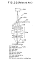
- Fig. 22 is an explanation drawing conceptually showing a filler wire-coaxial laser welding head 226 according to an earlier technology.
- the filler wire-coaxial laser welding head 226 has a structure in which a filler wire 207 is passed through holes perforated at the center of a total reflection mirror 214 and an imaging lens system 204.
- the filler wire 207 and an optical axis of a laser beam are rendered coaxial, and the filler wire-coaxial laser welding head 226 is designed to perform welding while feeding the filler wire 207 via a filler wire feed pipe 208.
- a laser beam 206 launched from an optical fiber 201 is reflected by the total reflection mirror 214, and condensed by the imaging lens system 204 for use in fusing a base material 216 and the filler wire 207.
- the filler wire 207 is fed by a filler wire feeder 209.
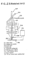
- Fig. 23 is an explanation drawing conceptually showing a TIG arc-coaxial laser welding head 227 according to an earlier technology.
- this TIG arc-coaxial laser welding head 227 arranges an electrode 210 for TIG welding and a laser beam optical axis coaxially, thereby performing TIG welding and laser welding simultaneously.
- Its constitution is basically the same as the constitution of the filler wire-coaxial laser welding head 226 shown in Fig. 22, the difference existing only in the electrode 210, an electrode holding pipe 211 for holding the electrode 210, and a welding power source 212.
- Fig. 24 is a vertical sectional view showing the constitution of a tip portion of a conventional, typical laser beam machining head.
- a laser beam machining head 301 shown in the drawing is provided in a laser beam machine (its machine body is not shown) which cuts an object 302 to be cut, such as carbon steel.
- a lens-barrel 305 houses a condensing optical system (an imaging lens system) 304 composed of a plurality of lenses 310, and a protective glass 307 for protecting the condensing optical system 304.
- the condensing optical system 304 condenses laser light 303, and projects it onto a cutting site 302a of the object 302 to be cut.
- a focal position, f, of the laser light 303 condensed by the condensing optical system 304 is usually adjusted to lie within the object 302 to be cut, as illustrated in the drawing.
- the laser light 303 is generated by a laser oscillator such as a YAG laser oscillator (not shown), and then transmitted to the condensing optical system 304 by an optical transmission means such as an optical fiber or mirrors (not shown).
- an assist gas nozzle 306 is attached in such a manner as to surround the laser light 303 that has been ejected from the condensing optical system 304.
- the assist gas nozzle 306 is shaped like a truncated cone with a tip side (lower end side) becoming thin, and has an opening 306a at the tip side.
- an assist gas supply pipe 308 is connected to a side surface of the assist gas nozzle 306, to a side surface of the assist gas nozzle 306, an assist gas supply pipe 308 is connected.
- the assist gas supply pipe 308 is tied to an assist gas supply device (not shown) .
- an assist gas Q T transported from the assist gas supply device is introduced into the assist gas nozzle 306 via the assist gas supply pipe 308, and is jetted through the tip opening 306a of the assist gas nozzle 306 toward the cutting site 302a of the object 302 to be cut.
- a cutting operation for the object 302 to be cut, by means of the laser beam machine equipped with the laser beam machining head 301 of the above-described constitution, is performed in the following manner: First, the laser beam machining head 301 is brought close to the object 302 to be cut, by the use of a laser beam machining head moving device (not shown) . Also, the distance between the tip of the assist gas nozzle 306 and the surface of the object 302 to be cut (i.e., work distance), h, is kept so that there will be no contact between the assist gas nozzle 306 and the object 302 to be cut. In this condition, either the laser beam machining head 301 is moved by the laser beam machining head moving device in a direction perpendicular to the sheet face of Fig. 24, or the object 302 to be cut is moved by a work moving device (not shown) in a direction opposite to the moving direction of the laser beam machining head.
- the laser beam machining head 301 condenses the laser light 303 by the condensing optical system 304, and projects it onto the cutting site 302a of the object 302 to be cut, thereby fusing the cutting site 302a.
- an assist gas is jetted toward the cutting site 302a from the tip opening 306a of the assist gas nozzle 306, and introduced into the cutting site 302a, to blow away and remove fused metal within the cutting site 302a.
- the object 302 to be cut is laser cut.
- the composite welding head 223 shown in Fig. 21 has two welding heads, i.e., the laser welding head 224 and the TIG welding head 225.
- This composite welding head 223 is large in size, and its direction of welding cannot be selected freely, because the two constituent welding heads are at fixed positions, i.e., front and rear positions. Thus, this type of welding head is not suitable for welding an object of a three dimensional shape.
- the center of the laser beam 206 launched from the optical fiber 201 is the site of the strongest intensity distribution of light. This site is the very place where the filler wire feed pipe 208 is situated.
- the laser beam 206 projected onto the filler wire feed pipe 208 is irregularly reflected, causing a beam transmission loss. Such a laser beam may not be used effectively depending on a purpose to be attained.
- the present invention has been accomplished in view of the above-described problems with the earlier technologies. It is an object of the invention to provide a laser beam machining head which can satisfactorily perform welding of an object of a complicated shape, such as a three-dimensional shape, and can also achieve efficient welding without causing a loss in a laser beam projected.
- the laser beam machining head of the present invention that attains the above object is characterized by the following:
- the manner of flowing the assist gas to the cutting site 302a i.e., the flow velocity and flow rate of the assist gas jetted at the cutting site 302a, greatly affect cutting performance.
- the diameter of the opening (the width of the opening), d, of the assist gas nozzle 306 is considerably greater than the cutting width (kerf width), w, (in laser cutting, the cutting width w is as small as, say, 2 to 3 mm) .
- the entire assist gas Q T jetted from the assist gas nozzle 306 is divided into an assist gas Q 2 which is fed into the cutting site 302a, and assist gases Q 3 , Q 4 which flow to both sides of the cutting site 302a through the clearance between the assist gas nozzle 306 and the object 302 to be cut.
- assist gas Q T introduced into the assist gas nozzle 306 i.e., assist gas Q 2
- assist gas Q 2 the assist gas Q T introduced into the assist gas nozzle 306
- the efficiency of removal of fused metal by the assist gas is so low that the cutting performance is low.
- the gas pressure cannot be increased, because of restrictions imposed by the pressure-resistant strength of the optical parts.
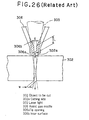
- the tip opening 306a of the assist gas nozzle 306 may be thinned, in comparison with the earlier technologies, to make the opening diameter d and the cutting width W nearly equal. By so doing, most of the assist gas introduced into the assist gas nozzle 306 flows into the cutting site 302a, and the velocity of the assist gas jetted becomes greater than before.
- a zone with a length L (>4d) in a tip portion of the assist gas nozzle 306 may be set at a constant internal diameter, d. This stabilizes the flow of the assist gas, increasing its directivity.
- part of the laser light 303 interferes with an inner surface 306b of the assist gas nozzle 306 (i.e., a shaded portion in Fig. 26) at the tip portion of the assist gas nozzle 306.
- an inner surface 306b of the assist gas nozzle 306 i.e., a shaded portion in Fig. 26
- the laser light 303 is not projected effectively onto the object 302 to be cut, with the result that the cutting performance is decreased.
- the opening diameter d of the assist gas nozzle 306 is restricted by the breadth of the laser light 303 at the tip opening 306a, and thus cannot be made smaller than the width over which the laser light 303 broadens.
- the pattern at the cutting site 302a points obliquely in a direction opposite to the direction of cutting.
- a substantial thickness of the plate to be cut increases compared with the actual plate thickness T, resulting in a decrease in the cutting ability.
- the cutting ability of the laser light 303 for the object 302 to be cut is affected by the position of the focal position f of the laser light 303 relative to the object 302 to be cut.
- Customary practice has been to adjust the focal position f of the laser light 303 to rest in the interior, in the direction of plate thickness, of the object 302 to be cut, as shown in Fig. 24. If this focal position f can be suitably adjusted depending on the material and thickness of the object 302 to be cut, an increase in the cutting performance can be expected.
- the assist gas nozzle 306 also moves in the direction of plate thickness to change the distance between the assist gas nozzle 306 and the object 302 to be cut. Consequently, there may be a decrease in the ability of the assist gas to remove fused metal.
- the assist gas nozzle 306 should be made as close as possible to the object 302 to be cut. If the laser beam machining head 301 is moved upward in Fig. 24 to move upward the focal position f of the laser light 303 relative to the object 302 to be cut, the assist gas nozzle 306 also moves upward accordingly, increasing the spacing h between the assist gas nozzle 306 and the object 302 to be cut. Thus, the ability of the assist gas to remove fused metal lowers.
- the assist gas nozzle 306 is brought close to the object 302 to be cut, by contrast, the focal position f of the laser light 303 relative to the object 302 to be cut is moved, and the assist gas nozzle 306 interferes with the object 302 to be cut.
- the laser beam machining head of the present invention that solves the aforementioned problems is characterized by the following:
- Fig. 1 is a sectional view showing a filler wire-coaxial laser welding head according to a first embodiment of the present invention.
- a filler wire-coaxial laser welding head 21 has a convex roof mirror 2 and a pierced concave roof mirror 3.
- a laser beam 206 launched from an optical fiber 201 is reflected by the convex roof mirror 2, whereby it is divided into two separate beams.
- the two separate laser beams 206 are reflected by the pierced concave roof mirror 3, and guided to an imaging lens system 204.
- the pierced concave roof mirror 3 is a mirror having a hole formed at its center for passage of a filler wire feed pipe 208.
- each laser beam 206 has its center out of contact with the filler wire feed pipe 208, as will be described later on in Fig. 3, and passes through the imaging lens system 204. Then, the separate laser beams 206 converge at an imaging plane on the surface of a base material 216, realizing keyhole welding in which a filler wire 207 and the base material 216 have been fused.
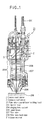
- Fig. 2 is a sectional view showing a TIG arc-coaxial laser welding head according to a second embodiment of the present invention.
- a TIG arc-coaxial laser welding head 22 also has a convex roof mirror 2 and a pierced concave roof mirror 3.
- a laser beam 206 launched from an optical fiber 201 is reflected by the convex roof mirror 2, whereby it is divided into two separate beams.
- the resulting two separate laser beams 206 are reflected by the pierced concave roof mirror 3, which has a hole formed for passage of an electrode holding pipe 211, and are then guided to an imaging lens system 204.
- each separate laser beam 206 has its center out of contact with the electrode holding pipe 211, and passes through the imaging lens system 204. Then, the separate laser beams 206 converge at an imaging plane on the surface of a base material 216. The so converged laser beam 206 and arc heat generated by an electrode 210 for TIG welding fuse the base material 216 to realize keyhole welding. At this time, the position of the optical fiber 201 can be changed freely on a plane normal to the optical axis of the laser beam 206 by an optical fiber drive shaft 15.
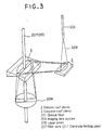
- Fig. 3 is an explanation view for illustrating the division of the laser beam 206 into two separate beams by a combination of convex and concave roof mirrors in the first and second embodiments.
- the laser beam 206 launched from the optical fiber 201 is divided at its center into two separate beams by the convex roof mirror 2 which is projected at the center in the shape of a mountain, and which is composed of two mirrors.
- the laser beam 206 is converted into two semicircular laser beams 206, which are reflected by the convex roof mirror 2.
- the laser beam 206 launched from the optical fiber 201 is circular in shape, while the laser beam 206 divided by the convex roof mirror 2 is formed into two semicircular laser beams 206 and reflected toward the concave roof mirror 3. Then, these separate laser beams 206 are reflected by the concave roof mirror 3, which is depressed at the center in the shape of a valley and which is composed of two mirrors, and are then incident on the imaging lens system 204 composed of a plurality of pierced lenses. As a result of reflection by the convex roof mirror 2, the circular laser beam 206 turns into semicircular beams.
- the distance between these semicircular beams can be changed according to the placement of the mirrors 2, 3 which are optical systems, and the angles of the vertices of the mountain and the valley of the convex roof mirror 2 and the concave roof mirror 3, respectively.
- the filler wire feed pipe 208 or the electrode holding pipe 211 is situated between these semicircular beams.
- the filler wire feed pipe 208 or the electrode holding pipe 211 is not irradiated with the laser beam 6.
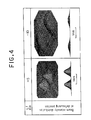
- Fig. 4 is an explanation drawing showing beam intensity distributions of the laser beam 206 at positions 5 mm and 10 mm deviated toward lenses from the imaging surface during the condensing process in the laser beam machining head involving the combination of the concave and convex roof mirrors in the first and second embodiments.
- the laser beam 206 is divided into two separate beams as far as a site near the imaging surface because of the combination of the convex roof mirror 2 and the concave roof mirror 3.
- a high intensity distribution of the laser beam 206 is not located at the position of the filler wire supply pipe 208 or the electrode holding pipe 211 laid at the center.
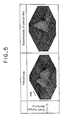
- the laser beams 206 condensed are somewhat defocused, whereby twin beams with varied intensities can be created as shown in Fig. 5.
- the beam intensities of the two beams 206 condensed at the condensing site can be varied relatively freely by adjusting the position of the optical fiber 201 with the use of the optical fiber drive shaft 15 (see Fig. 2; the same constitution is provided, although not shown, in Fig. 1), or by making the convex roof mirror 2 and the concave roof mirror 3 movable perpendicularly in two directions on a plane normal to the optical axis.
- the structures shown in Figs. 1 to 3 are designed to divide the laser beam 206 into two semicircular beams by the use of the convex roof mirror 2 and the concave roof mirror 3, thereby suppressing or preventing the irradiation of the filler wire feed pipe 208 or the electrode holding pipe 211 with the laser beam.
- the structure of an optical system having a hole formed at the center of the convex roof mirror 3 and also a hole formed at the center of the imaging lens system 204 is expensive because of man-hours in production, and so forth.
- the optical system is liable to be damaged by the filler wire feed pipe 208 or the electrode holding pipe 211. It is recommendable to use the concave roof mirror 3 and the imaging lens system 204 that are ordinary (holeless).
- the inventors made the improvement of performing satisfactory welding of an object of a complicated shape, such as a three-dimensional shape, by using an ordinary concave roof mirror 3 and an ordinary imaging lens system 204, and arranging the optical axis of a laser beam and the filler wire 207 or electrode 210 in a coaxial fashion.
- the inventors also added the improvement of performing efficient welding free from irradiation of the filler wire feed pipe or the electrode holding pipe with a laser beam.
- Fig. 6(a) is a schematic view showing a head in which a filler wire 207 and an optical axis of a laser beam 206 are arranged coaxially at a beam condensing position by the use of a concave roof mirror 3 and an imaging lens system 204 which are ordinary (hole-free).
- a laser beam launched from an optical fiber 201 is divided into two semicircular laser beams 206 by a convex roof mirror 2 and the concave roof mirror 3, and these semicircular laser beams are spaced from each other by a certain distance.
- These separate laser beams 206 from the concave roof mirror 3 are condensed via the imaging lens system 204.
- the concave roof mirror 3 and the imaging lens system 204 are ordinary, hole-free optical parts.
- a filler wire feed pipe 208 is placed adjacent to and along the imaging lens system 204.
- the filler wire 207 is fed within the filler wire feed pipe 208 so as to become parallel to the optical axis of the laser beam 206.
- a filler wire guide 17 is provided at the lower end of the filler wire feed pipe 208.
- the filler wire guide 17 is located below the imaging lens system 204 for guiding the filler wire 207 coaxially with the optical axis of the laser beam 206.
- the filler wire guide 17 has a slender rectangular shape, and has a hole, formed from an upper portion at one end thereof to a lower portion at the other end thereof, for guiding the filler wire.
- the filler wire guide 17 is formed in a slender shape so as to be positioned between the two semicircular laser beams 206 that have left the imaging lens system 204.
- the filler wire guide 17 is free from irradiation with the laser beams 206.
- the separate laser beams 206 are condensed and converged toward a base material into a bundle of beams.
- the filler wire guide 17 cannot be placed very close to the condensing position, but is placed above the condensing position.
- the lower portion of the filler wire guide 17 may be tapered so that the filler wire guide 17 will be wedge-shaped overall. In either case, direct irradiation of the filler wire guide 17 with the laser beams can be avoided.
- the direction of the filler wire 207 can be changed inside the filler wire guide 17.
- it is permissible, as shown in Fig. 6(c) to divide the filler wire guide 17 into a plurality of pieces in a vertical direction, form straight holes in the resulting separate pieces 17a, 17b, 17c, and connect these holes together. This enables the passage hole to be formed easily.
- the filler wire guide 17 is divided into the three separate pieces 17a, 17b, 17c. If the filler wire guide 17 is divided into more pieces, however, the filler wire 207 can be guide more smoothly.
- the filler wire guide 17 can be divided not only vertically as shown in Fig. 6(c), but also in a horizontal (length) direction.
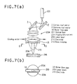
- Fig. 6 has shown an improvement utilizing the filler wire guide 17, while Fig. 7 shows an improvement in an electrode 210 for TIG welding. That is, the head of Fig. 7 has the electrode 210 of tungsten and an optical axis of a laser beam 206 coaxially arranged with the use of a concave roof mirror 3 and an imaging lens system 204 which are ordinary (not holed).
- a laser beam launched from an optical fiber 201 is divided into two semicircular, spaced laser beams 206, and condensed onto a base material 216, as in Fig. 6.
- the electrode 210 is placed opposite the base material 216, on an optical axis of the original laser beam 206, and between the two separate beams such that the electrode 210 is not directly irradiated with these beams.
- This electrode 210 is supported by a water flow pipe 18, which is parallel to the lens surface and passes between the two separate laser beams 206, and a voltage is applied to the electrode 210.
- a tip of the electrode 210 is tapered according to the degree of condensation of the separate laser beams 206.
- a front end of the electrode 210 is not brought very close to the base material 216 in order to generate an arc.
- the degree of the taper can be determined in consideration of the degree of separation of the electrode 210 from the base material 216.
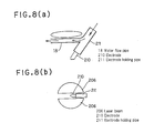
- Fig. 8(a) shows a structure in which the electrode 210 is held obliquely from beside the imaging lens system 204.
- an electrode holding pipe 211 concurrently serves as the water flow pipe 18 until midway, and from there, the water flow pipe 18 is branched to become parallel to the lens surface.
- the electrode 210 has its front end positioned on the optical axis of the original laser beam 206.
- the electrode 210, as well as the electrode holding pipe 211, is located between the two separate laser beams 206, as shown in Fig. 8(b).
- the intensity of the condensed beam can be varied by positional adjustment using the optical fiber drive shaft 15 shown in Fig. 2, or by the movement of the convex roof mirror and the concave roof mirror.
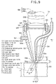
- Fig. 9 is a vertical sectional view showing a constitution of a tip portion of a laser beam machining head according to a fifth embodiment of the present invention.
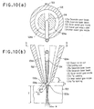
- Fig. 10(a) is a cross sectional view showing the constitution of the tip portion of the laser beam machining head (a sectional view taken along line D-D in Fig. 10(b)).
- Fig. 10(b) is a vertical sectional view taken in a direction of an arrow C in Fig. 9.
- Fig. 11 is a constitution drawing of an optical system provided in the laser beam machining head.
- Fig. 12 is a perspective view showing a constitution of a dividing optical system in the above optical system.
- a laser beam machining head 121 shown in Figs. 9 and 10 (a) and 10 (b) is provided in a laser beam machine (its machine body is not shown) for cutting an object 122 to be cut, such as carbon steel.
- a condensing optical system (an imaging lens system) 124, and a protective glass 125 for protecting the condensing optical system 124 are provided in a lens-barrel 123.
- the condensing optical system 124 condenses two separate laser beams 126a, 126b (to be described later on in detail) created by division, and projects the resulting condensed light onto a cutting site 122a of the object 122 to be cut.
- a focal position, f, of the laser beams 126a, 126b condensed by the condensing optical system 124 is usually adjusted to lie within the object 122 to be cut, as illustrated.
- the optical system of the laser beam machining head 121 is composed of the condensing optical system 124 and a dividing optical system 127.
- the condensing optical system 124 is composed of a plurality of lenses 128 disposed vertically with suitable spacing from each other.
- the dividing optical system 127 is composed of a concave roof mirror 129 and a convex roof mirror 130 as a pair.
- the concave roof mirror 129 is disposed obliquely above the condensing optical system 124, while the convex roof mirror 130 is disposed obliquely to be opposed to the concave roof mirror 129.
- a tip portion of an optical fiber 131 is located above the convex roof mirror 130.
- laser light 126 is emitted by a YAG laser oscillator (not shown), then transmitted through the optical fiber 131, and ejected from the tip of the optical fiber 131 toward mirrors 130a, 130b of the convex roof mirror 130.
- the concave roof mirror 129 is depressed at the center in the shape of a valley, and comprises two mirrors 129a, 129b.
- the convex roof mirror 130 projects at the center in the shape of a mountain, and comprises the two mirrors 130a, 130b.
- the laser light 126 launched from the optical fiber 131 is reflected by the convex roof mirror 130 as two semicircular laser beams 126a, 126b divided from the laser light 126 at the center. That is, the laser light 126 from the optical fiber 131 is circular in cross section. Whereas the laser light 126, reflected and divided by the mirrors 130a, 130b of the convex roof mirror 130, becomes the two semicircular separate laser beams 126a, 126b, which are transmitted to the concave roof mirror 129, with these beams being spaced from each other.
- the separate laser beams 126a, 126b are reflected by the mirrors 129a, 129b of the concave roof mirror 129, respectively, and transmitted to the condensing optical system 124.
- the laser beams 126a, 126b are condensed and projected onto the cutting site 122a of the object 122 to be cut, as stated earlier (see Figs. 9, 10 (a) and 10 (b)).
- the spacing between the separate laser beams 126a and 126b can be adjusted by changing the arrangement of the convex roof mirror 130 and the concave roof mirror 129, and the angles of the vertices of the mountain and the valley of the convex roof mirror 130 and the concave roof mirror 129.
- an outer assist gas nozzle 132 is attached so as to surround the separate laser beams 126a, 126b launched from the condensing optical system 124, as shown in Figs. 9, 10(a) and 10 (b) .
- the outer assist gas nozzle 132 is shaped like a truncated cone with a tip side (lower end side) becoming thin, and has an opening 132a at the tip side.
- an assist gas supplypipe 133 is connected to a side surface of the outer assist gas nozzle 132.
- the assist gas supply pipe 133 is tied to an assist gas supply device (not shown) .
- an assist gas Q 2T transported from the assist gas supply device is introduced into the outer assist gas nozzle 132 via the assist gas supply pipe 108, and is jetted through the tip opening 132a of the outer assist gas nozzle 132 toward the cutting site 122a of the object 122 to be cut.
- the outer assist gas nozzle 132 is provided to protect the condensing optical system 124.
- the outer assist gas nozzle 132 itself protects the condensing optical system 124 from a metallic vapor, heat, etc. generated during cutting.
- jets of an assist gas from the tip opening 132a of the outer assist gas nozzle 132 prevent metallic vapor, etc. from penetrating through the tip opening 132a into the outer assist gas nozzle 132.
- an inner assist gas nozzle 134 is fixed in such a manner as to pass through this side surface.
- This inner assist gas nozzle 134 is in the shape of a thin tube, and is placed between the separate laser beams 126a and 126b.
- the inner assist gas nozzle 134 gradually thins toward its tip side (lower end side), and an opening diameter (opening width) d i of its tip opening 134a is nearly equal to a cutting width (kerf width) w (e.g., 2 to 3 mm) of the cutting site 122a of the object 122 to be cut.
- the opening diameter d i is equal to the cutting width w
- a case in which the opening diameter d i is slightly smaller than the cutting width w the illustrated case. Even if the opening diameter d i is somewhat larger than the cutting width w, this is more effective than the earlier technologies.
- the inner assist gas nozzle 134 can be placed between the separate laser beams 126a and 126b.
- the so placed inner assist gas nozzle 134 can be formed into a desired thinness without interference with the separate laser beams 126a and 126b.
- the inner assist gas nozzle 134 is tied to the assist gas supply device (not shown) via the assist gas supply pipe (not shown). That is, an assist gas Q 1T transported from the assist gas supply device is introduced into the inner assist gas nozzle 134 via the assist gas supply pipe, and is jetted through the tip opening 134a of the inner assist gas nozzle 134 toward the cutting site 122a of the object 122 to be cut. Most of the assist gas Q 1T is fed into the cutting site 122a.
- a zone with a length L (>4d i ) in the tip portion of the inner assist gas nozzle 134 is set at a constant internal diameter d i . This stabilizes the flow of the assist gas jetted from the inner assist gas nozzle 134, thereby increasing its directivity.
- a cutting operation for the object 122 to be cut, by means of the laser beam machine equipped with the laser beam machining head 121 of the present fifth embodiment, is performed in the following manner: First, the laser beam machining head 121 is brought close to the object 122 to be cut, by the use of a laser beam machining head moving device (not shown). Also, the distance between the tips of the inner assist gas nozzle 134 and the outer assist gas nozzle 132 and the surface of the object 122 to be cut (i.e., work distance), h, is kept at, say, 3 to 4 mm so that there will be no contact of the inner assist gas nozzle 134 and the outer assist gas nozzle 132 with the object 122 to be cut.
- either the laser beam machining head 121 is moved by the laser beam machining head moving device in a direction perpendicular to the sheet face of Fig. 9, or the object 122 to be cut is moved by a work moving device (not shown) in a direction opposite to the moving direction of the laser beam machining head.
- the laser beam machining head 121 divides the laser light 126 into two beams by the dividing optical system 127, condenses these separate laser beams 126a, 126b by the condensing optical system 124, and projects the condensed light onto the cutting site 122a of the object 122 to be cut, thereby fusing the cutting site 122a.
- an assist gas is jetted from the tip opening 132a of the outer assist gas nozzle 132 to prevent penetration of metallic vapor, etc. into the outer assist gas nozzle 132 and protect the condensing optical system 124.
- an assist gas is jetted from the tip opening 134a of the inner assist gas nozzle 134, and introduced into the cutting site 122a, to blow away fused metal within the cutting site 122a and remove it therefrom.
- the object 122 to be cut is laser cut.
- the assist gas jetted from the outer assist gas nozzle 132 flows out to both sides of the cutting site 122a from the gap between the outer assist gas nozzle 132 and the object 122 to be cut (assist gases Q 3 , Q 4 ).
- the assist gas jetted from the inner assist gas nozzle 134 is mostly fed into the cutting site 122a, because the opening diameter d i of the inner assist gas nozzle 134 is nearly equal to the cutting width w.
- the assist gas can be fed with high efficiency into the cutting site 122a.
- the amount of assist gas fed into the cutting site 122a can be increased markedly in comparison with the earlier technologies.
- the opening diameter d i of the inner assist gas nozzle 134 is so small that the jet velocity of the assist gas jetted from the inner assist gas nozzle 134 becomes much higher than in the earlier technologies.
- the gas pressure can also be raised, without restrictions imposed by the pressure resistant strength of the optical parts. Because of these advantages, the kinetic energy of the assist gas fed into the cutting site 122a becomes great. Thus, the ability of the assist gas to remove fused metal increases remarkably, and the cutting ability is enhanced markedly.
- Fig. 14 shows a comparison between the cutting speed obtained by the use of the conventional laser beam machining head 301 (see Fig. 24) and the cutting speed obtained by the use of the laser beam machining head 121 according to the present fifth embodiment.
- the cutting speed for the laser beam machining head 121 of the present fifth embodiment is much higher than the cutting speed for the conventional laser beam machining head 301.
- the outer assist gas nozzle 132 is provided on the laser light exit side of the condensing optical system 124, and the assist gas is also jetted from this outer assist gas nozzle 132. Thus, protection of the condensing optical system 124 can be ensured.
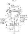
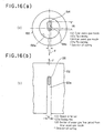
- Fig. 15 is a vertical sectional view showing a constitution of a tip portion of a laser beam machining head according to a sixth embodiment of the present invention.
- Fig. 16(a) is an enlarged view taken on line E-E in Fig. 15, and
- Fig. 16(b) is a view taken on line H-H in Fig. 15 on which a section of an assist gas flow jetted through an inner assist gas nozzle has been superimposed.
- a laser beam machining head 121 according to the present sixth embodiment is the same as the laser beam machining head 121 of the fifth embodiment (see Fig. 9), except the constitution concerning an inner assist gas nozzle 134 to be described later on. Thus, a detailed description of this same constitution is omitted here.
- a tip opening 134a of the inner assist gas nozzle 134 is thin and elongated along a direction of cutting (a direction of an arrow F). Namely, an opening width d i of the tip opening 134a is nearly equal to a cutting width w of an object 122 to be cut, and an opening length d 1 of the tip opening 134a is larger than the opening width d i .
- This slender tip opening 134a has a head portion situated above a center c of a tip opening 132 of an outer assist gas nozzle 132 and extending from this position in a direction opposite to the direction of cutting.
- the tip opening 134a of the inner assist gas nozzle 134 is in such a slender shape that its opening width d i is nearly equal to the cutting width w of the object 122 to be cut, and its opening length d i is larger than the opening width d i .
- a section 135 of an assist gas flow shown in Fig. 16(b) most of an assist gas jetted from the inner assist gas nozzle 134 can be fed into a cutting site 122a.
- a larger channel area than in the fifth embodiment can be provided, so that the flow rate of the assist gas jetted from the inner assist gas nozzle 134 (fed into the cutting site 122a) can be increased.
- the amount of the assist gas fed from the assist gas supply device is adjusted to make the velocity of the assist gas jetted from the inner assist gas nozzle 134 in the present sixth embodiment equal to the velocity of the assist gas jetted from the inner assist gas nozzle 134 in the aforementioned fifth embodiment.
- the flow rate of the assist gas jetted from the inner assist gas nozzle 134 in the former becomes greater than the flow rate of the assist gas jetted from the inner assist gas nozzle 134 in the latter.
- the present sixth embodiment can feed the assist gas efficiently into the cutting site 122a, raise the jet velocity of the assist gas, and increase the jet flow rate of the assist gas.
- the ability of the assist gas to remove fused metal is even higher than in the fifth embodiment. Consequently, the cutting ability for the object 122 to be cut increases further.
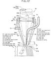
- Fig. 17 is a vertical sectional view showing a constitution of a tip portion of a laser beam machining head according to a seventh embodiment of the present invention.
- a laser beam machining head 121 according to the present seventh embodiment is the same as the laser beam machining head 121 of the aforementioned fifth embodiment (see Fig. 9), except the constitution concerning an inner assist gas nozzle 134 to be described later on. Thus, a detailed description of this same constitution is omitted here.
- Fig. 17 shows, in the laser beam machining head 121 of the present seventh embodiment, the inner assist gas nozzle 134 is fixed to a side surface of an outer assist gas nozzle 132, with a tip side of the inner assist gas nozzle 134 is inclined at an inclination angle ⁇ in a direction of cutting (Fig. 17 shows cutting in a direction of an arrow G).
- laser light 126 is divided by a dividing optical system 127 (see Fig. 12) into two separate laser beams 126a, 126b, and the inner assist gas nozzle 134 is placed between these separate laser beams 126a and 126b. Because of this constitution, a condensing optical system 124 need not be inclined, but only the inner assist gas nozzle 134 can be set in an inclined state.
- an opening diameter (opening width) d i of a tip opening 134a is nearly equal to a cutting width of an object 122 to be cut.
- the tip opening 134a of the inner assist gas nozzle 134 may be in such a slender, elongated shape along a cutting direction that, as in the aforementioned sixth embodiment, the opening width d i is nearly equal to the cutting width of the object 122 to be cut, and its opening length is larger than the opening width d i .
- the constitution of the inner assist gas nozzle 134 is such that the opening diameter (opening width) d i of the tip opening 134a is nearly equal to the cutting width of the object 122 to be cut, and the tip side of the inner assist gas nozzle 134 is inclined in the cutting direction.
- the assist gas jetted from the inner assist gas nozzle 134 can be fed into a cutting site 122a.
- the assist gas is blown onto the cutting site 122a (the site of fusion upon irradiation with the separate laser beams 126a, 126b) obliquely relative to the cutting direction.
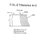
- the assist gas is jetted just downward (in a direction at right angles to the cutting direction) at the cutting site 122a as shown in Fig. 27, fused metal is relatively prone to flow in a direction opposite to the direction of cutting, so that a substantial thickness of the plate to be cut becomes larger than the actual plate thickness T.
- the ability of the assist gas to remove fused metal is enhanced to make the fused metal easier to flow downwardly (because of difficulty in flowing of the fused metal in the direction opposite to the cutting direction).
- the substantial thickness of the plate cut becomes close to the actual plate thickness T, resulting in a further increase in the cutting ability.
- Fig. 18 is a vertical sectional view showing a constitution of a tip portion of a laser beam machining head according to an eighth embodiment of the present invention.
- a laser beam machining head 121 according to the present eighth embodiment is the same as the laser beam machining head 121 of the aforementioned fifth embodiment (see Fig. 9), except the constitution concerning an inner assist gas nozzle 134 to be described later on. Thus, a detailed description of this same constitution is omitted here. Illustration of a support system for the inner assist gas nozzle 134 is also omitted.
- a tip side of the inner assist gas nozzle 134 is inclined (inclination angle 6) in a direction of cutting (Fig. 18 shows cutting in a direction of an arrow G).
- the inner assist gas nozzle 134 is fixed to the outer assist gas nozzle 132 (the inclination angle ⁇ is fixed).
- the inclination angle ⁇ of the inner assist gas nozzle 134 can be varied independently of a direction of projection of laser beams 126a, 126b.
- a hole 136 having a vertical width w 2 larger than the diameter of the inner assist gas nozzle 134 is formed in a side surface of the outer assist gas nozzle 132.
- the inner assist gas nozzle 134 is inserted into this hole 136.
- the inner assist gas nozzle 134 can be changed in the inclination angle ⁇ independently of a condensing optical system 124 and as indicated by a two-dot chain line in Fig. 18, without being restrained by the outer assist gas nozzle 132.
- laser light 126 is divided by a dividing optical system 127 (see Fig. 12) into two separate laser beams 126a, 126b, and the inner assist gas nozzle 134 is placed between these separate laser beams 126a and 126b. Because of this constitution, only the inner assist gas nozzle 134 can be inclined independently of the condensing optical system 124, and as in the present eighth embodiment, the inclination angle ⁇ of the inner assist gas nozzle 134 can be varied.
- a drive device 137 such as an electricmotor, a hydraulic cylinder, or a pneumatic air cylinder, and the inner assist gas nozzle 134 may be coupled together via a suitable link mechanism using a gear, shaft or the like, and the inner assist gas nozzle 134 may be pivoted by the drive device 137.
- an operator may change the inclination angle ⁇ of the inner assist gas nozzle 134.
- an opening diameter (opening width) d i of a tip opening 134a is nearly equal to a cutting width of an object 122 to be cut.
- the tip opening 134a of the inner assist gas nozzle 134 may be in such a slender, elongated shape along a cutting direction that, as in the aforementioned seventh embodiment, the opening width d i is nearly equal to the cutting width of the object 122 to be cut, and its opening length is larger than the opening width d i .
- the hole 136 formed in the side surface of the outer assist gas nozzle 132 remains open. As such, part of an assist gas introduced from an assist gas supply pipe 133 may leak through the hole 136. For this and other reasons, if protection of the condensing optical system 124 may not be fully ensured, it is desirable to stop up the hole 136, i.e., to close the gap between the inner peripheral surface of the hole 136 and the outer peripheral surface of the inner assist gas nozzle 134, in order to protect the condensing optical system 124 reliably. In this case, the gap may be closed with such a sufficiently flexible member as not to impede the pivoting of the inner assist gas nozzle 134.
- Cutting of the object 122 to be cut, by means of a laser beam machine equipped with the laser beam machining head 121 of the present eighth embodiment also gives the same actions and effects as those in the aforementioned fifth and seventh embodiments, although its detailed description will be omitted.
- the inclination angle ⁇ of the inner assist gas nozzle 134 can be changed.
- an optimal inclination angle ⁇ adapted for the plate thickness, material, etc. of the object 122 to be cut can be selected.
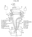
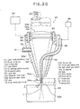
- Figs. 19 and 20 are each a vertical sectional view showing a constitution of a tip portion of a laser beam machining head according to a ninth embodiment of the present invention.
- a laser beam machining head 121 according to the present ninth embodiment is the same as the laser beam machining head 121 of the aforementioned fifth embodiment (see Fig. 9), except the constitution concerning an inner assist gas nozzle 134 to be described later on. Thus, a detailed description of this same constitution is omitted here. Illustration of a support system for the inner assist gas nozzle 134 is also omitted.
- the inner assist gas nozzle 134 is fixed to an outer assist gas nozzle 132.
- the relative positions of the inner assist gas nozzle 134 and the object 122 to be cut can be varied independently of the relative positions of a focal position f of a condensing optical system 124 and the object 122 to be cut (distance d f from the surface of the object 122 to be cut to the focal position f) ; or the relative positions of the focal position f of the condensing optical system 124 and the object 122 to be cut can be varied independently of the relative positions of the inner assist gas nozzle 134 and the object 122 to be cut.
- a hole 138 having a vertical width w 3 sufficiently larger than the outer diameter of the inner assist gas nozzle 134 is formed in a side surface of the outer assist gas nozzle 132.
- the inner assist gas nozzle 134 is inserted through this hole 138.
- the vertical position of the inner assist gas nozzle 134 can be changed without being restrained by the outer assist gas nozzle 132, i.e., independently of the condensing optical system 124, whereby the relative positions of the inner assist gas nozzle 134 and the object 122 to be cut (spacing h) can be changed.
- the vertical position of the condensing optical system 124 is changed independently of the inner assist gas nozzle 134, whereby the relative positions of the focal position f of the condensing optical system 124 and the object 122 to be cut (distance d f ) can be changed.
- Fig. 20 shows a case in which the distance d f has been made small.
- laser light 126 is divided by a dividing optical system 127 (see Fig. 12) into two separate laser beams 126a, 126b, and the inner assist gas nozzle 134 is placed between these separate laser beams 126a and 126b. Because of this constitution, only the inner assist gas nozzle 134 can be moved up and down independently of the condensing optical system 124, or only the condensing optical system 124 can be moved up and down independently of the inner assist gas nozzle 134.
- a drive device 139 such as an electric motor or a cylinder
- the inner assist gas nozzle 134 may be coupled together via a suitable link mechanism using a gear, shaft or the like, and the inner assist gas nozzle 134 may be moved vertically by the drive device 139.
- the inner assist gas nozzle 134 may be moved vertically by a manual force.
- a drive device 140 such as an electric motor or a cylinder, or a manual force may be employed.
- an opening diameter (opening width) d i of a tip opening 134a is nearly equal to a cutting width w of the object 122 to be cut.
- the tip opening 134a of the inner assist gas nozzle 134 may be in such a slender, elongated shape along a cutting direction (a direction perpendicular to the sheet face of Figs. 19 and 20) that, as in the aforementioned seventh embodiment, the opening width d i is nearly equal to the cutting width w of the object 122 to be cut, and its opening length is larger than the opening width d i .
- the hole 138 formed in the side surface of the outer assist gas nozzle 132 remains open. As such, part of an assist gas introduced from an assist gas supply pipe 133 may leak through the hole 138. For this and other reasons, if protection of the condensing optical system 124 may not be fully ensured, it is desirable to stop up the hole 138, i.e., to close the gap between the inner peripheral surface of the hole 138 and the outer peripheral surface of the inner assist gas nozzle 134, in order to protect the condensing optical system 124 reliably. In this case, the gap may be closed with such a sufficiently flexible member as not to impede the vertical movement of the inner assist gas nozzle 134 or the condensing optical system 124.
- the relative positions of the inner assist gas nozzle 134 and the object 122 to be cut can be varied independently of the relative positions of the focal position f of the condensing optical system 124 and the object 122 to be cut (distance d f ); or the relative positions of the focal position f of the condensing optical system 124 and the object 122 to be cut can be varied independently of the relative positions of the inner assist gas nozzle 134 and the object 122 to be cut.
- the relative positions of the inner assist gas nozzle 134 and the object 122 to be cut can be adjusted to optimal positions without inducing changes in the relative positions of the focal position f of the condensing optical system 124 and the object 122 to be cut (distance d f ). That is, the inner assist gas nozzle 134 can be brought as close as possible to the object 122 to be cut, such that the interference between the inner assist gas nozzle 134 and the object 122 to be cut can be avoided. This increases the ability of the assist gas to remove fused metal, thereby increasing the cutting ability.
- the relative positions of the focal position f of the condensing optical system 124 and the object 122 to be cut can be adjusted to optimal positions adapted to the material, thickness, etc. of the object 122 to be cut, without inducing changes in the relative positions of the inner assist gas nozzle 134 and the object 122 to be cut (spacing h) . This also results in an increase in the cutting ability.
- the laser beam machining head of the present invention is not restricted to a laser beam machine using a YAG laser oscillator, but can also be applied to a laser beam machine using other laser oscillator.
- the inner assist gas nozzle 134 in each of the fifth to ninth embodiments is a straight nozzle having a tip portion L whose inner diameter is constant (d i ).
- the inner diameter of this tip portion need not be constant, but the nozzle may have a slightly widened tip side.
- Such a nozzle with a widened tip side is known as a divergent nozzle.
- the divergent nozzle is used as the inner assist gas nozzle 134, the flow velocity of the assist gas can be made the sound velocity or higher.
- the inner assist gas nozzle 134 As a method for providing the inner assist gas nozzle 134 between the separate laser beams 126a and 126b, it is conceivable to pierce the center of the concave roof mirror 129 and the center of each lens 128 of the condensing optical system 124 shown in Fig. 11, and insert the inner assist gas nozzle 134 of a straight shape into the resulting holes. In this case, however, the resulting laser beam machining head is expensive because of man-hours in production, and so forth. Besides, the optical system is liable to be damaged by the inner assist gas nozzle 134.
- the fifth to ninth embodiments have been described in connection with cutting of a workpiece.
- the fifth to ninth embodiments are effective when applied to piercing of a workpiece.
- the opening width (opening diameter) di of the tip portion of the inner assist gas nozzle 134 is rendered nearly equal to the hole diameter of the piercing site of the workpiece.
- a convex roof mirror and a concave roof mirror are combined to divide a laser beam in two.
- the laser beam at a condensing portion can be divided into two parts.
- a laser beam is divided in two so that no laser beam is projected onto a filler wire feed pipe or an electrode holding pipe for various arcs such as TIG, MAG and plasma arcs.
- laser beam can be efficiently and intensively projected onto a base material for welding.
- the filler wire feed pipe or the electrode holding pipe for various arcs such as TIG, MAG and plasma arcs is coaxial with the laser beam.
- satisfactory welding can be performed for an object of a complicated shape, such as a three-dimensional shape, without hindrance to workability.
- a filler wire is fed from outside separate laser beams to a beam condensing position via a filler wire guide in the spacing between the separate laser beams, and an electrode is brought close to the beam condensing position by a water flow pipe or an electrode holding pipe.
- the position of an optical fiber for laser beam transmission, or the convex roof mirror and the concave roof mirror can be moved relative to the center of lenses in two directions perpendicular to the optical axis in a plane perpendicular to the optical axis.
- the ratio of the intensities of the two separate laser beams, or the position of the laser beam can be changed as desired.
- a laser beam machining head of a laser beam machine for projecting laser light onto a workpiece, and also blowing an assist gas at the workpiece to cut or pierce the workpiece, comprises:
- the assist gas jetted from the inner assist gas nozzle is mostly fed into the cutting site or the piercing site, because the opening diameter of the inner assist gas nozzle is nearly equal to the cutting width or the hole diameter.
- the assist gas can be fed with high efficiency into the cutting site or the piercing site.
- the opening diameter of the inner assist gas nozzle is so small that the jet velocity of the assist gas jetted from the inner assist gas nozzle becomes much higher than in the earlier technologies.
- the gas pressure can also be raised, without restrictions imposed by the pressure resistant strength of the optical parts. Because of these advantages, the kinetic energy of the assist gas fed into the cutting site or the piercing site becomes great.
- the ability of the assist gas to remove fused metal increases remarkably, and the cutting ability or piercing ability is enhanced markedly.
- a laser beam machining head of a laser beam machine for projecting laser light onto a workpiece, and also blowing an assist gas at the workpiece to cut the workpiece, comprises:
- the tip opening of the inner assist gas nozzle is in such a slender shape that its opening width is nearly equal to the cutting width of the object to be cut, and its opening length is larger than the opening width.
- most of an assist gas jetted from the inner assist gas nozzle can be fed into the cutting site.
- the channel area is increased, so that the flow rate of the assist gas jetted from the inner assist gas nozzle (fed into the cutting site) can be increased.
- this aspect of the invention can feed the assist gas efficiently into the cutting site, raise the jet velocity of the assist gas, and increase the jet flow rate of the assist gas.
- the ability of the assist gas to remove fused metal is further increased. Consequently, the cutting ability increases further.
- a laser beam machining head of a laser beam machine for projecting laser light onto a workpiece, and also blowing an assist gas at the workpiece to cut the workpiece, comprises:
- the constitution of the inner assist gas nozzle is such that the opening width of the tip opening is nearly equal to the cutting width of the object to be cut, and the tip side of the inner assist gas nozzle is inclined in the cutting direction.
- the assist gas is blown onto the cutting site (the site of fusion upon irradiation with the separate laser beams) obliquely relative to the cutting direction.
- the ability of the assist gas to remove fused metal is enhanced to make the fused metal easier to flow downwardly (because of difficulty in flowing of the fused metal in the direction opposite to the cutting direction). Therefore, the substantial thickness of the plate to be cut becomes close to the actual plate thickness, resulting in a further increase in the cutting ability.
- the laser beam machining head of the eighth aspect of the invention is such that an angle of inclination of the inner assist gas nozzle can be varied independently of a direction of projection of the laser light.
- the inclination angle of the inner assist gas nozzle can be changed. By performing trial cutting with this inclination angle varied, for example, an optimal inclination angle adapted for the plate thickness, material, etc. of the object to be cut can be selected. Hence, the ability of the assist gas to remove fused metal increases further, and the substantial plate cutting thickness becomes close to the actual plate thickness, resulting in a further increase in the cutting ability.
- a laser beam machining head of a laser beam machine for projecting laser light onto a workpiece, and also blowing an assist gas at the workpiece to cut or pierce the workpiece, comprises:
- the relative positions of the inner assist gas nozzle and the workpiece can be adjusted to optimal positions without inducing changes in the relative positions of the focal position of the condensing optical system and the workpiece. That is, the inner assist gas nozzle can be brought as close to the workpiece as possible such that interference between the inner assist gas nozzle and the workpiece can be avoided. This increases the ability of the assist gas to remove fused metal, thereby increasing the machining ability.
- the relative positions of the focal position of the condensing optical system and the workpiece can be adjusted to optimal positions adapted to the material, thickness, etc. of the workpiece, without inducing changes in the relative positions of the inner assist gas nozzle and the workpiece. This also results in an increase in the machining ability.
- an outer assist gas is provided at an exit side of the condensing optical system so as to surround the separate laser beams launched from the condensing optical system, and the assist gas is also jetted through a tip opening of the outer assist gas nozzle.
- the outer assist gas nozzle is provided, and the assist gas is jetted from this outer assist gas nozzle as well, protection of the condensing optical system can be ensured.
Landscapes
- Physics & Mathematics (AREA)
- Optics & Photonics (AREA)
- Engineering & Computer Science (AREA)
- Plasma & Fusion (AREA)
- Mechanical Engineering (AREA)
- Laser Beam Processing (AREA)
Abstract
Description
a convex roof mirror and a concave roof mirror are combined to divide the laser beam in two, thereby forming two separate laser beams to be condensed so that no laser beam is projected onto a filler wire feed pipe or an electrode holding pipe.
a convex roof mirror and a concave roof mirror are combined to divide the laser beam in two, thereby forming two separate laser beams to be condensed, with spacing being present between the two separate laser beams, and the filler wire is fed to a condensing position via a filler wire guide in the spacing between the two separate laser beams from a filler wire feed pipe disposed outside the laser beams.
a convex roof mirror and a concave roof mirror are combined to divide the laser beam in two, thereby forming two separate laser beams to be condensed, with spacing being present between the two separate laser beams, and a tip of the electrode is held above a condensing position while the electrode is supported by a water flow pipe or an electrode holding pipe passing through the spacing between the laser beams.
Claims (11)
- A laser beam machining head, comprising:
a convex roof mirror and a concave roof mirror combined to divide a laser beam in two, thereby forming two separate laser beams to be condensed. - A laser beam machining head which is a filler wire- or a TIG, MAG or plasma arc-coaxial laser welding head comprising a filler wire or an electrode for various arcs such as TIG, MAG and plasma arcs, and an optical axis of a laser beam, the filler wire or the electrode and the optical axis being coaxially arranged, wherein:
a convex roof mirror and a concave roof mirror are combined to divide the laser beam in two, thereby forming two separate laser beams to be condensed so that no laser beam is projected onto a filler wire feed pipe or an electrode holding pipe. - A laser beam machining head which is a filler wire-coaxial laser welding head comprising a filler wire, and an optical axis of a laser beam, wherein:
a convex roof mirror and a concave roof mirror are combined to divide the laser beam in two, thereby forming two separate laser beams to be condensed, with spacing being present between the two separate laser beams, and the filler wire is fed to a condensing position via a filler wire guide in the spacing between the two separate laser beams from a filler wire feed pipe disposed outside the laser beams. - A laser beam machining head which is a TIG, MAG or plasma arc-coaxial laser welding head comprising an electrode for various arcs such as TIG, MAG and plasma arcs and an optical axis of a laser beam, wherein:
a convex roof mirror and a concave roof mirror are combined to divide the laser beam in two, thereby forming two separate laser beams to be condensed, with spacing being present between the two separate laser beams, and a tip of the electrode is held above a condensing position while the electrode is supported by a water flow pipe or an electrode holding pipe passing through the spacing between the laser beams. - The laser beam machining head of claim 1, 2, 3 or 4, wherein:
the ratio of the intensities of the two separate laser beams, or the position of the laser beam is changed by making the position of an optical fiber for laser beam transmission, or the convex roof mirror and the concave roof mirror, movable relative to a lens center in two directions perpendicular to the optical axis in a plane perpendicular to the optical axis. - A laser beam machining head of a laser beam machine for projecting laser light onto a workpiece, and also blowing an assist gas at the workpiece to cut or pierce the workpiece, comprising:a dividing optical system for dividing the laser light into at least two separate laser beams, and providing spacing between the separate laser beams;a condensing optical system for condensing the separate laser beams into condensed laser light, and projecting the condensed laser light onto a cutting site or a piercing site of the workpiece; andan inner assist gas nozzle placed between the separate laser beams, a width of an opening of a tip portion of the inner assist gas nozzle being nearly equal to a cutting width of the cutting site, or a hole diameter of the piercing site.
- A laser beam machining head of a laser beam machine for projecting laser light onto a workpiece, and also blowing an assist gas at the workpiece to cut the workpiece, comprising:a dividing optical system for dividing the laser light into at least two separate laser beams, and providing spacing between the separate laser beams;a condensing optical system for condensing the separate laser beams into condensed laser light, and projecting the condensed laser light onto a cutting site of the workpiece; andan inner assist gas nozzle placed between the separate laser beams, a width of an opening of a tip portion of the inner assist gas nozzle being nearly equal to a cutting width of the cutting site, and a length of the opening of the tip portion being larger than the width of the opening.
- A laser beam machining head of a laser beam machine for projecting laser light onto a workpiece, and also blowing an assist gas at the workpiece to cut the workpiece, comprising:a dividing optical system for dividing the laser light into at least two separate laser beams, and providing spacing between the separate laser beams;a condensing optical system for condensing the separate laser beams into condensed laser light, and projecting the condensed laser light onto a cutting site of the workpiece; andan inner assist gas nozzle placed between the separate laser beams, a width of an opening of a tip portion of the inner assist gas nozzle being nearly equal to a cutting width of the cutting site, and a tip side of the inner assist gas nozzle being inclined in a direction of cutting.
- The laser beam machining head of claim 8, wherein: an angle of inclination of the inner assist gas nozzle can be varied independently of a direction of projection of the laser light.
- A laser beam machining head of a laser beam machine for projecting laser light onto a workpiece, and also blowing an assist gas at the workpiece to cut or pierce the workpiece, comprising:a dividing optical system for dividing the laser light into at least two separate laser beams, and providing spacing between the separate laser beams;a condensing optical system for condensing the separate laser beams into condensed laser light, and projecting the condensed laser light onto a cutting site or a piercing site of the workpiece; andan inner assist gas nozzle placed between the separate laser beams, a width of an opening of a tip portion of the inner assist gas nozzle being nearly equal to a cutting width of the cutting site, or a hole diameter of the piercing site, and wherein:relative positions of the inner assist gas nozzle and the workpiece can be varied independently of relative positions of a focal position of the condensing optical system and the workpiece; or the relative positions of the focal position of the condensing optical system and the workpiece can be varied independently of the relative positions of the inner assist gas nozzle and the workpiece.
- The laser beam machining head of claim 6, 7, 8, 9 or 10, wherein:
an outer assist gas nozzle is provided at an exit side of the condensing optical system so as to surround the separate laser beams launched from the condensing optical system, and the assist gas is also jetted through a tip opening of the outer assist gas nozzle.
Applications Claiming Priority (2)
| Application Number | Priority Date | Filing Date | Title |
|---|---|---|---|
| JP799999 | 1999-01-14 | ||
| JP00799999A JP3664904B2 (en) | 1999-01-14 | 1999-01-14 | Laser processing head |
Publications (3)
| Publication Number | Publication Date |
|---|---|
| EP1020249A2 true EP1020249A2 (en) | 2000-07-19 |
| EP1020249A3 EP1020249A3 (en) | 2001-08-22 |
| EP1020249B1 EP1020249B1 (en) | 2003-06-11 |
Family
ID=11681103
Family Applications (1)
| Application Number | Title | Priority Date | Filing Date |
|---|---|---|---|
| EP99121418A Expired - Lifetime EP1020249B1 (en) | 1999-01-14 | 1999-10-27 | Laser beam machining head |
Country Status (4)
| Country | Link |
|---|---|
| US (2) | US6294754B1 (en) |
| EP (1) | EP1020249B1 (en) |
| JP (1) | JP3664904B2 (en) |
| DE (1) | DE69908745T2 (en) |
Cited By (15)
| Publication number | Priority date | Publication date | Assignee | Title |
|---|---|---|---|---|
| FR2813031A1 (en) * | 2000-08-21 | 2002-02-22 | Air Liquide | METHOD AND INSTALLATION FOR HYBRID LASER-ARC WELDING USING A LASER WITH POWER DIODES |
| FR2817782A1 (en) * | 2000-12-13 | 2002-06-14 | Air Liquide | Installation for laser beam cutting or welding using a double flow of assisting gas and a double focusing of the laser beam |
| DE10113471A1 (en) * | 2001-03-19 | 2002-10-02 | Highyag Lasertechnologie Gmbh | Welding materials using a laser beam used in hybrid welding processes comprises directing two laser focussing points in the welding point or in the region of the melt produced around the welding point |
| FR2823688A1 (en) * | 2001-04-24 | 2002-10-25 | Commissariat Energie Atomique | Apparatus for melting a material by a laser beam, especially for forming a coating on a substrate, comprises a material supply line and optical elements for distributing and focusing the laser beam |
| EP1270139A1 (en) * | 2001-06-22 | 2003-01-02 | Lödige Fördertechnik GmbH | Scanning assembly for a power laser |
| EP1179382A3 (en) * | 2000-08-10 | 2004-08-18 | Mitsubishi Heavy Industries, Ltd. | Laser beam machining head and laser beam machining apparatus having same |
| EP1568435A1 (en) * | 2004-02-28 | 2005-08-31 | Trumpf Laser- und Systemtechnik GmbH | Laser machining device |
| WO2005118209A1 (en) * | 2004-05-27 | 2005-12-15 | Hentze-Lissotschenko Patentverwaltungs Gmbh & Co. Kg | Device for welding or soldering by means of laser radiation |
| DE102007018400A1 (en) | 2007-04-17 | 2008-10-30 | Fraunhofer-Gesellschaft zur Förderung der angewandten Forschung e.V. | Optical system for laser processing head has collimation unit in front of first optical unit and at least one axicon after collimation unit |
| EP2361714A1 (en) | 2010-02-26 | 2011-08-31 | Reis Group Holding GmbH & Co. KG | Method and assembly for laser soldering |
| CN102325627A (en) * | 2009-02-23 | 2012-01-18 | 小池酸素工业株式会社 | Laser cutting method and laser cutting device |
| CN108500491A (en) * | 2017-02-24 | 2018-09-07 | 苏州柘电智能科技有限公司 | The coaxial compound increasing material manufacturing device and method of laser-cold metal transfer electric arc |
| WO2019056713A1 (en) * | 2017-09-20 | 2019-03-28 | 苏州大学张家港工业技术研究院 | Laser cladding device |
| US10926353B2 (en) | 2016-10-25 | 2021-02-23 | Prima Power Laserdyne, Llc | Dual gas pierce using coaxial and directional assist |
| CN113231741A (en) * | 2021-04-26 | 2021-08-10 | 南京航空航天大学 | Laser welding device and method based on annular facula coaxial wire feeding |
Families Citing this family (55)
| Publication number | Priority date | Publication date | Assignee | Title |
|---|---|---|---|---|
| US6881925B1 (en) * | 1997-12-09 | 2005-04-19 | Kabushiki Kaisha Toshiba | Laser emission head, laser beam transmission device, laser beam transmission device adjustment method and preventive maintenance/repair device of structure in nuclear reactor |
| JP2001276988A (en) * | 2000-03-30 | 2001-10-09 | Mitsubishi Heavy Ind Ltd | Laser processing apparatus |
| EP1273383B1 (en) * | 2000-04-10 | 2009-12-02 | Mitsubishi Heavy Industries, Ltd. | Welding system |
| US6639177B2 (en) * | 2001-03-29 | 2003-10-28 | Gsi Lumonics Corporation | Method and system for processing one or more microstructures of a multi-material device |
| JP2002331377A (en) * | 2001-05-08 | 2002-11-19 | Koike Sanso Kogyo Co Ltd | Laser piercing method |
| US20030062126A1 (en) * | 2001-10-03 | 2003-04-03 | Scaggs Michael J. | Method and apparatus for assisting laser material processing |
| US7012216B2 (en) * | 2002-02-08 | 2006-03-14 | Honeywell International | Hand-held laser welding wand having internal coolant and gas delivery conduits |
| EP1498214B1 (en) * | 2002-04-01 | 2016-03-09 | Honda Giken Kogyo Kabushiki Kaisha | Yag laser induced arc filler wire composite welding method |
| US20040094526A1 (en) * | 2002-11-15 | 2004-05-20 | Mccoy Edward D. | Cutting laser beam nozzle assembly |
| US7057134B2 (en) * | 2003-03-18 | 2006-06-06 | Loma Linda University Medical Center | Laser manipulation system for controllably moving a laser head for irradiation and removal of material from a surface of a structure |
| US7379483B2 (en) * | 2003-03-18 | 2008-05-27 | Loma Linda University Medical Center | Method and apparatus for material processing |
| US7286223B2 (en) * | 2003-03-18 | 2007-10-23 | Loma Linda University Medical Center | Method and apparatus for detecting embedded rebar within an interaction region of a structure irradiated with laser light |
| US7880116B2 (en) * | 2003-03-18 | 2011-02-01 | Loma Linda University Medical Center | Laser head for irradiation and removal of material from a surface of a structure |
| US7038166B2 (en) * | 2003-03-18 | 2006-05-02 | Loma Linda University Medical Center | Containment plenum for laser irradiation and removal of material from a surface of a structure |
| US7060932B2 (en) | 2003-03-18 | 2006-06-13 | Loma Linda University Medical Center | Method and apparatus for material processing |
| US7754999B2 (en) * | 2003-05-13 | 2010-07-13 | Hewlett-Packard Development Company, L.P. | Laser micromachining and methods of same |
| US7038162B2 (en) * | 2003-11-13 | 2006-05-02 | Honeywell International, Inc. | Hand-held laser welding wand filler media delivery systems and methods |
| US7664154B2 (en) * | 2004-04-21 | 2010-02-16 | Mitsubishi Electric Corporation | Gas laser oscillator and gas laser beam machine |
| EP1632305A1 (en) * | 2004-09-04 | 2006-03-08 | Trumpf Werkzeugmaschinen GmbH + Co. KG | Process for determining and process for adjusting the reciprocal position of the axis of a laser machining beam and the axis of a processing gas jet on a laser working machine as well as laser working machine with equipment for executing the processes |
| DE102005000631A1 (en) * | 2005-01-03 | 2006-07-13 | Siemens Ag | Device for laser beam welding on lateral surfaces of rotationally symmetrical components |
| CN100409993C (en) * | 2006-04-06 | 2008-08-13 | 龙岩理尚精密机械有限公司 | CNC laser cutting head and manufacturing method thereof |
| US7851984B2 (en) | 2006-08-08 | 2010-12-14 | Federal-Mogul World Wide, Inc. | Ignition device having a reflowed firing tip and method of construction |
| FR2908677B1 (en) * | 2006-11-17 | 2009-02-20 | Air Liquide | LASER BEAM WELDING METHOD WITH ENHANCED PENETRATION |
| DE102007059987B4 (en) * | 2007-12-11 | 2015-03-05 | Trumpf Werkzeugmaschinen Gmbh + Co. Kg | Method for keyhole-free laser fusion cutting by means of leading and trailing laser beams |
| JP5398165B2 (en) * | 2008-04-24 | 2014-01-29 | 三菱重工業株式会社 | Laser / arc combined welding head and method thereof |
| US8105712B2 (en) * | 2008-08-08 | 2012-01-31 | Panasonic Corporation | Sealed secondary battery, and method for manufacturing the battery |
| FR2936177B1 (en) * | 2008-09-24 | 2011-08-26 | Air Liquide | LASER WELDING PROCESS OF CO2 TYPE WITH DYNAMIC JET NOZZLE. |
| DE102008053729C5 (en) * | 2008-10-29 | 2013-03-07 | Trumpf Werkzeugmaschinen Gmbh + Co. Kg | Laser processing nozzle for processing sheet metal |
| JPWO2011016200A1 (en) * | 2009-08-05 | 2013-01-10 | パナソニック株式会社 | Sealed battery and manufacturing method thereof |
| CN102652046B (en) * | 2009-12-16 | 2014-12-31 | 依赛彼公司 | A welding process and a welding arrangement |
| DE102010018686B4 (en) * | 2010-04-22 | 2017-08-17 | Fraunhofer-Gesellschaft zur Förderung der angewandten Forschung e.V. | Apparatus and method for laser cladding with powdered filler material |
| EP2409808A1 (en) * | 2010-07-22 | 2012-01-25 | Bystronic Laser AG | Laser processing machine |
| JP2012035313A (en) * | 2010-08-10 | 2012-02-23 | Ihi Corp | Laser beam cutting method |
| US9289852B2 (en) | 2011-01-27 | 2016-03-22 | Bystronic Laser Ag | Laser processing machine, laser cutting machine, and method for adjusting a focused laser beam |
| EP2667998B1 (en) | 2011-01-27 | 2020-11-18 | Bystronic Laser AG | Laser processing machine and method for centering a focused laser beam |
| CN104114316B (en) * | 2012-02-14 | 2015-11-25 | 村田机械株式会社 | Laser processing machine |
| DE102012207201B3 (en) | 2012-04-30 | 2013-04-11 | Trumpf Werkzeugmaschinen Gmbh + Co. Kg | Method for laser-assisted plasma cutting or plasma welding and apparatus therefor |
| WO2013174449A1 (en) | 2012-05-25 | 2013-11-28 | European Space Agency | Multi-wire feeder method and system for alloy sample formation and additive manufacturing |
| KR102096048B1 (en) * | 2012-10-10 | 2020-04-02 | 삼성디스플레이 주식회사 | Laser Processing apparatus |
| JP6053598B2 (en) * | 2013-04-18 | 2016-12-27 | 株式会社アマダミヤチ | Laser cutting method, laser emitting unit and laser cutting device |
| EP2883647B1 (en) | 2013-12-12 | 2019-05-29 | Bystronic Laser AG | Method for configuring a laser machining device |
| WO2016027186A1 (en) * | 2014-08-19 | 2016-02-25 | Koninklijke Philips N.V. | Sapphire collector for reducing mechanical damage during die level laser lift-off |
| JP6807334B2 (en) * | 2015-05-13 | 2021-01-06 | ルミレッズ ホールディング ベーフェー | Sapphire collector to reduce mechanical damage during die-level lift-off |
| JP6190855B2 (en) * | 2015-09-08 | 2017-08-30 | 株式会社アマダホールディングス | Laser processing method and laser processing apparatus |
| JP6802550B2 (en) * | 2016-02-25 | 2020-12-16 | 国立研究開発法人日本原子力研究開発機構 | Cutting device and cutting method for double pipe structure |
| CN110167755B (en) | 2017-01-05 | 2022-04-08 | Ipg光子公司 | Additive laser processing system and method |
| CN110997218A (en) * | 2017-06-09 | 2020-04-10 | 伊利诺斯工具制品有限公司 | Coaxial laser heating filament head |
| CN107498140B (en) * | 2017-08-28 | 2019-12-17 | 大族激光科技产业集团股份有限公司 | Laser coaxial brazing device and laser welding method |
| KR101994996B1 (en) * | 2017-11-20 | 2019-07-02 | 한국생산기술연구원 | Minute-hole Drilling Device Using Electron Beam |
| JP6725605B2 (en) | 2018-08-24 | 2020-07-22 | ファナック株式会社 | Laser processing system and laser processing method |
| WO2020261537A1 (en) | 2019-06-28 | 2020-12-30 | 三菱重工業株式会社 | Laser machining device |
| IL290911B2 (en) * | 2019-08-27 | 2026-01-01 | Edison Welding Inst Inc | Coaxial laser-wire optical system for use in additive manufacturing |
| CN111438448A (en) * | 2020-05-11 | 2020-07-24 | 无锡超通智能制造技术研究院有限公司 | A kind of laser processing equipment and method for free composite separation of galvanometer and nozzle |
| CN113020810B (en) * | 2021-01-27 | 2023-03-24 | 重庆恒格光电科技有限公司 | Nine unification battery of lens cutting device |
| CN116475598B (en) * | 2023-04-27 | 2026-04-21 | 上海波刺自动化科技有限公司 | Detection device and laser cutting system |
Family Cites Families (11)
| Publication number | Priority date | Publication date | Assignee | Title |
|---|---|---|---|---|
| JPS5439340A (en) | 1977-09-02 | 1979-03-26 | Mitsubishi Electric Corp | Laser welder |
| JPS583478B2 (en) * | 1978-03-03 | 1983-01-21 | 株式会社日立製作所 | Laser heating method and device |
| US4167662A (en) * | 1978-03-27 | 1979-09-11 | National Research Development Corporation | Methods and apparatus for cutting and welding |
| JPS59218292A (en) * | 1983-05-25 | 1984-12-08 | Mitsubishi Electric Corp | Laser working device |
| JPH04182088A (en) * | 1990-11-17 | 1992-06-29 | Kobe Steel Ltd | Condensing device for laser beam machining |
| JP3083320B2 (en) * | 1991-11-19 | 2000-09-04 | アドバンスド・テクニック・ゲーエムベーハー | Apparatus for removing material from a metal workpiece that is moved relative to a removal tool |
| JP3248275B2 (en) * | 1992-12-25 | 2002-01-21 | いすゞ自動車株式会社 | Laser processing equipment |
| JPH08108289A (en) * | 1994-10-07 | 1996-04-30 | Sumitomo Electric Ind Ltd | Laser processing optical device |
| JP3392683B2 (en) * | 1997-02-10 | 2003-03-31 | 三菱重工業株式会社 | Laser processing head |
| JP3868116B2 (en) * | 1997-09-26 | 2007-01-17 | 三菱重工業株式会社 | Laser processing head |
| JP3268248B2 (en) * | 1997-11-25 | 2002-03-25 | 三菱重工業株式会社 | Composite welding head |
-
1999
- 1999-01-14 JP JP00799999A patent/JP3664904B2/en not_active Expired - Fee Related
- 1999-10-27 DE DE69908745T patent/DE69908745T2/en not_active Expired - Lifetime
- 1999-10-27 EP EP99121418A patent/EP1020249B1/en not_active Expired - Lifetime
- 1999-10-29 US US09/429,079 patent/US6294754B1/en not_active Expired - Lifetime
-
2001
- 2001-08-03 US US09/920,823 patent/US6417487B2/en not_active Expired - Lifetime
Cited By (25)
| Publication number | Priority date | Publication date | Assignee | Title |
|---|---|---|---|---|
| EP1179382A3 (en) * | 2000-08-10 | 2004-08-18 | Mitsubishi Heavy Industries, Ltd. | Laser beam machining head and laser beam machining apparatus having same |
| WO2002016071A1 (en) * | 2000-08-21 | 2002-02-28 | L'air Liquide, Societe Anonyme A Directoire Et Conseil De Surveillance Pour L'etude Et L'exploitation Des Procedes Georges Claude | Method and installation for hybrid laser/arc welding using a power-diode laser |
| FR2813031A1 (en) * | 2000-08-21 | 2002-02-22 | Air Liquide | METHOD AND INSTALLATION FOR HYBRID LASER-ARC WELDING USING A LASER WITH POWER DIODES |
| US6664504B2 (en) | 2000-12-13 | 2003-12-16 | L'air Liquide - Societe Anonyme A Directoire Et Conseil De Surveillance Pour L'etude Et L'exploitation Des Procedes Georges Claude | Method and plant for laser cutting with dual-flow and double-focus cutting head |
| FR2817782A1 (en) * | 2000-12-13 | 2002-06-14 | Air Liquide | Installation for laser beam cutting or welding using a double flow of assisting gas and a double focusing of the laser beam |
| EP1215008A1 (en) * | 2000-12-13 | 2002-06-19 | L'AIR LIQUIDE, Société Anonyme à Directoire et Conseil de Surveillance pour l'Etude et l'Exploitation des | Process and installation for laser cutting with a double stream and double-focus cutting head |
| DE10113471B4 (en) * | 2001-03-19 | 2005-02-17 | Highyag Lasertechnologie Gmbh | Method for hybrid welding by means of a laser double focus |
| DE10113471A1 (en) * | 2001-03-19 | 2002-10-02 | Highyag Lasertechnologie Gmbh | Welding materials using a laser beam used in hybrid welding processes comprises directing two laser focussing points in the welding point or in the region of the melt produced around the welding point |
| FR2823688A1 (en) * | 2001-04-24 | 2002-10-25 | Commissariat Energie Atomique | Apparatus for melting a material by a laser beam, especially for forming a coating on a substrate, comprises a material supply line and optical elements for distributing and focusing the laser beam |
| EP1270139A1 (en) * | 2001-06-22 | 2003-01-02 | Lödige Fördertechnik GmbH | Scanning assembly for a power laser |
| US7449659B2 (en) | 2004-02-28 | 2008-11-11 | Trumpf Laser- Und Systemtechnik Gmbh | Laser processing machine |
| EP1568435A1 (en) * | 2004-02-28 | 2005-08-31 | Trumpf Laser- und Systemtechnik GmbH | Laser machining device |
| WO2005118209A1 (en) * | 2004-05-27 | 2005-12-15 | Hentze-Lissotschenko Patentverwaltungs Gmbh & Co. Kg | Device for welding or soldering by means of laser radiation |
| DE102007018400A1 (en) | 2007-04-17 | 2008-10-30 | Fraunhofer-Gesellschaft zur Förderung der angewandten Forschung e.V. | Optical system for laser processing head has collimation unit in front of first optical unit and at least one axicon after collimation unit |
| DE102007018400B4 (en) * | 2007-04-17 | 2009-04-02 | Fraunhofer-Gesellschaft zur Förderung der angewandten Forschung e.V. | Optical system for a laser material processing head |
| CN102325627A (en) * | 2009-02-23 | 2012-01-18 | 小池酸素工业株式会社 | Laser cutting method and laser cutting device |
| CN102325627B (en) * | 2009-02-23 | 2015-01-07 | 小池酸素工业株式会社 | Laser cutting method and laser cutting device |
| EP2361714A1 (en) | 2010-02-26 | 2011-08-31 | Reis Group Holding GmbH & Co. KG | Method and assembly for laser soldering |
| DE102010016628A1 (en) | 2010-02-26 | 2011-09-29 | Reis Group Holding Gmbh & Co. Kg | Method and arrangement for the cohesive joining of materials |
| US8698039B2 (en) | 2010-02-26 | 2014-04-15 | Reis Group Holding Gmbh & Co. Kg | Method and arrangement for firm bonding of materials |
| US10926353B2 (en) | 2016-10-25 | 2021-02-23 | Prima Power Laserdyne, Llc | Dual gas pierce using coaxial and directional assist |
| CN108500491A (en) * | 2017-02-24 | 2018-09-07 | 苏州柘电智能科技有限公司 | The coaxial compound increasing material manufacturing device and method of laser-cold metal transfer electric arc |
| WO2019056713A1 (en) * | 2017-09-20 | 2019-03-28 | 苏州大学张家港工业技术研究院 | Laser cladding device |
| CN113231741A (en) * | 2021-04-26 | 2021-08-10 | 南京航空航天大学 | Laser welding device and method based on annular facula coaxial wire feeding |
| CN113231741B (en) * | 2021-04-26 | 2022-04-19 | 南京航空航天大学 | Laser welding device and method based on annular facula coaxial wire feeding |
Also Published As
| Publication number | Publication date |
|---|---|
| DE69908745T2 (en) | 2004-04-22 |
| DE69908745D1 (en) | 2003-07-17 |
| JP3664904B2 (en) | 2005-06-29 |
| US6294754B1 (en) | 2001-09-25 |
| EP1020249A3 (en) | 2001-08-22 |
| JP2000202672A (en) | 2000-07-25 |
| US20020017513A1 (en) | 2002-02-14 |
| EP1020249B1 (en) | 2003-06-11 |
| US6417487B2 (en) | 2002-07-09 |
Similar Documents
| Publication | Publication Date | Title |
|---|---|---|
| US6294754B1 (en) | Laser beam machining head | |
| EP1179382B1 (en) | Laser beam machining head and laser beam machining apparatus having same | |
| JP7443566B2 (en) | Laser cutting method and laser cutting device | |
| EP1018395B1 (en) | Laser machining apparatus | |
| US4128753A (en) | Laser beam welding | |
| US7019256B2 (en) | Method and apparatus for composite YAG laser/arc welding | |
| US9102009B2 (en) | Method and apparatus for laser welding with mixed gas plasma suppression | |
| US5728993A (en) | Laser cutting of materials with plural beams | |
| US20080116175A1 (en) | Laser welding process with improved penetration | |
| KR970005525B1 (en) | Laser torch | |
| GB1591793A (en) | Laser welding | |
| JP5601003B2 (en) | Laser arc combined welding method and butt welding metal plate groove | |
| EP3412401B1 (en) | Laser welding device | |
| JP3752112B2 (en) | Laser processing apparatus and laser processing head | |
| US20090212028A1 (en) | Laser-arc hybrid welding head | |
| JP2019198885A (en) | Hybrid welding apparatus | |
| JP2003311456A (en) | Laser beam irradiating arc welding head | |
| JP3868116B2 (en) | Laser processing head | |
| JP2659860B2 (en) | Laser cutting method | |
| JP4374611B2 (en) | Laser processing equipment | |
| JPH07164171A (en) | Laser processing method | |
| JPH09216081A (en) | Laser beam cutting machine | |
| US7186946B2 (en) | Laser drilling | |
| JP3621753B2 (en) | Underwater laser welding equipment | |
| JP3752216B2 (en) | Laser welding head |
Legal Events
| Date | Code | Title | Description |
|---|---|---|---|
| PUAI | Public reference made under article 153(3) epc to a published international application that has entered the european phase |
Free format text: ORIGINAL CODE: 0009012 |
|
| 17P | Request for examination filed |
Effective date: 19991125 |
|
| AK | Designated contracting states |
Kind code of ref document: A2 Designated state(s): AT BE CH CY DE DK ES FI FR GB GR IE IT LI LU MC NL PT SE |
|
| AX | Request for extension of the european patent |
Free format text: AL;LT;LV;MK;RO;SI |
|
| PUAL | Search report despatched |
Free format text: ORIGINAL CODE: 0009013 |
|
| AK | Designated contracting states |
Kind code of ref document: A3 Designated state(s): AT BE CH CY DE DK ES FI FR GB GR IE IT LI LU MC NL PT SE |
|
| AX | Request for extension of the european patent |
Free format text: AL;LT;LV;MK;RO;SI |
|
| RIC1 | Information provided on ipc code assigned before grant |
Free format text: 7B 23K 26/06 A, 7B 23K 26/067 B, 7B 23K 26/14 B |
|
| 17Q | First examination report despatched |
Effective date: 20011120 |
|
| AKX | Designation fees paid |
Free format text: DE GB |
|
| GRAH | Despatch of communication of intention to grant a patent |
Free format text: ORIGINAL CODE: EPIDOS IGRA |
|
| GRAH | Despatch of communication of intention to grant a patent |
Free format text: ORIGINAL CODE: EPIDOS IGRA |
|
| GRAH | Despatch of communication of intention to grant a patent |
Free format text: ORIGINAL CODE: EPIDOS IGRA |
|
| GRAH | Despatch of communication of intention to grant a patent |
Free format text: ORIGINAL CODE: EPIDOS IGRA |
|
| GRAA | (expected) grant |
Free format text: ORIGINAL CODE: 0009210 |
|
| AK | Designated contracting states |
Designated state(s): DE GB |
|
| REG | Reference to a national code |
Ref country code: GB Ref legal event code: FG4D |
|
| REF | Corresponds to: |
Ref document number: 69908745 Country of ref document: DE Date of ref document: 20030717 Kind code of ref document: P |
|
| PLBE | No opposition filed within time limit |
Free format text: ORIGINAL CODE: 0009261 |
|
| STAA | Information on the status of an ep patent application or granted ep patent |
Free format text: STATUS: NO OPPOSITION FILED WITHIN TIME LIMIT |
|
| 26N | No opposition filed |
Effective date: 20040312 |
|
| REG | Reference to a national code |
Ref country code: GB Ref legal event code: 746 Effective date: 20040615 |
|
| PGFP | Annual fee paid to national office [announced via postgrant information from national office to epo] |
Ref country code: GB Payment date: 20051026 Year of fee payment: 7 |
|
| GBPC | Gb: european patent ceased through non-payment of renewal fee |
Effective date: 20061027 |
|
| PG25 | Lapsed in a contracting state [announced via postgrant information from national office to epo] |
Ref country code: GB Free format text: LAPSE BECAUSE OF NON-PAYMENT OF DUE FEES Effective date: 20061027 |
|
| REG | Reference to a national code |
Ref country code: DE Ref legal event code: R082 Ref document number: 69908745 Country of ref document: DE Representative=s name: ADVOTEC. PATENT- UND RECHTSANWAELTE, DE Ref country code: DE Ref legal event code: R081 Ref document number: 69908745 Country of ref document: DE Owner name: MITSUBISHI HEAVY INDUSTRIES MACHINE TOOL CO., , JP Free format text: FORMER OWNER: MITSUBISHI HEAVY INDUSTRIES, LTD., TOKYO, JP |
|
| PGFP | Annual fee paid to national office [announced via postgrant information from national office to epo] |
Ref country code: DE Payment date: 20181016 Year of fee payment: 20 |
|
| REG | Reference to a national code |
Ref country code: DE Ref legal event code: R071 Ref document number: 69908745 Country of ref document: DE |