EP1019229B1 - Verfahren zur herstellung einer form aus formplatten und eine formplatte hergestellt aus einer flachen platte - Google Patents
Verfahren zur herstellung einer form aus formplatten und eine formplatte hergestellt aus einer flachen platte Download PDFInfo
- Publication number
- EP1019229B1 EP1019229B1 EP98904603A EP98904603A EP1019229B1 EP 1019229 B1 EP1019229 B1 EP 1019229B1 EP 98904603 A EP98904603 A EP 98904603A EP 98904603 A EP98904603 A EP 98904603A EP 1019229 B1 EP1019229 B1 EP 1019229B1
- Authority
- EP
- European Patent Office
- Prior art keywords
- mold
- plates
- roll
- laser
- plate
- Prior art date
- Legal status (The legal status is an assumption and is not a legal conclusion. Google has not performed a legal analysis and makes no representation as to the accuracy of the status listed.)
- Expired - Lifetime
Links
- 238000004519 manufacturing process Methods 0.000 title claims abstract description 23
- 238000000034 method Methods 0.000 claims abstract description 57
- 239000002826 coolant Substances 0.000 claims abstract description 51
- 238000001816 cooling Methods 0.000 claims abstract description 35
- 238000000465 moulding Methods 0.000 claims abstract description 17
- 238000007789 sealing Methods 0.000 claims abstract description 7
- 238000001746 injection moulding Methods 0.000 claims abstract description 6
- 239000000110 cooling liquid Substances 0.000 claims abstract description 4
- 238000003698 laser cutting Methods 0.000 claims description 15
- 239000012812 sealant material Substances 0.000 claims description 9
- 125000006850 spacer group Chemical group 0.000 claims description 5
- 239000012809 cooling fluid Substances 0.000 claims description 4
- 239000000126 substance Substances 0.000 claims description 3
- 238000005520 cutting process Methods 0.000 claims description 2
- 238000009499 grossing Methods 0.000 claims description 2
- 230000008569 process Effects 0.000 abstract description 16
- 238000003754 machining Methods 0.000 abstract description 12
- 230000008901 benefit Effects 0.000 abstract description 10
- 238000002347 injection Methods 0.000 abstract description 6
- 239000007924 injection Substances 0.000 abstract description 6
- 238000001259 photo etching Methods 0.000 abstract description 2
- 239000000463 material Substances 0.000 description 24
- 239000012530 fluid Substances 0.000 description 13
- 238000005530 etching Methods 0.000 description 10
- 229920005989 resin Polymers 0.000 description 10
- 239000011347 resin Substances 0.000 description 10
- 230000006835 compression Effects 0.000 description 8
- 238000007906 compression Methods 0.000 description 8
- 239000007788 liquid Substances 0.000 description 6
- 229920003002 synthetic resin Polymers 0.000 description 6
- 239000000057 synthetic resin Substances 0.000 description 6
- 239000004020 conductor Substances 0.000 description 5
- 230000000694 effects Effects 0.000 description 4
- 230000013011 mating Effects 0.000 description 4
- 239000000565 sealant Substances 0.000 description 4
- 238000005452 bending Methods 0.000 description 3
- 238000009713 electroplating Methods 0.000 description 3
- 239000004745 nonwoven fabric Substances 0.000 description 3
- -1 polypropylene Polymers 0.000 description 3
- 230000002411 adverse Effects 0.000 description 2
- 230000008021 deposition Effects 0.000 description 2
- 230000002209 hydrophobic effect Effects 0.000 description 2
- 230000005012 migration Effects 0.000 description 2
- 238000013508 migration Methods 0.000 description 2
- 229920002120 photoresistant polymer Polymers 0.000 description 2
- 239000004033 plastic Substances 0.000 description 2
- 229920003023 plastic Polymers 0.000 description 2
- 238000009834 vaporization Methods 0.000 description 2
- 230000008016 vaporization Effects 0.000 description 2
- 239000004677 Nylon Substances 0.000 description 1
- 239000004698 Polyethylene Substances 0.000 description 1
- 239000004743 Polypropylene Substances 0.000 description 1
- 230000003190 augmentative effect Effects 0.000 description 1
- 230000015572 biosynthetic process Effects 0.000 description 1
- 238000004891 communication Methods 0.000 description 1
- 238000010924 continuous production Methods 0.000 description 1
- 229920001577 copolymer Polymers 0.000 description 1
- 230000001419 dependent effect Effects 0.000 description 1
- 230000001627 detrimental effect Effects 0.000 description 1
- 238000010790 dilution Methods 0.000 description 1
- 239000012895 dilution Substances 0.000 description 1
- 230000002349 favourable effect Effects 0.000 description 1
- 210000000567 greater sac Anatomy 0.000 description 1
- 238000007654 immersion Methods 0.000 description 1
- 239000012212 insulator Substances 0.000 description 1
- 229920001778 nylon Polymers 0.000 description 1
- 230000035515 penetration Effects 0.000 description 1
- 238000007747 plating Methods 0.000 description 1
- 238000009428 plumbing Methods 0.000 description 1
- 229920000728 polyester Polymers 0.000 description 1
- 229920000573 polyethylene Polymers 0.000 description 1
- 229920001155 polypropylene Polymers 0.000 description 1
- 230000036316 preload Effects 0.000 description 1
- 230000008439 repair process Effects 0.000 description 1
- 239000004065 semiconductor Substances 0.000 description 1
- 239000007787 solid Substances 0.000 description 1
- 230000003068 static effect Effects 0.000 description 1
- 229920005992 thermoplastic resin Polymers 0.000 description 1
- 238000011144 upstream manufacturing Methods 0.000 description 1
- 239000011800 void material Substances 0.000 description 1
- XLYOFNOQVPJJNP-UHFFFAOYSA-N water Substances O XLYOFNOQVPJJNP-UHFFFAOYSA-N 0.000 description 1
Images


Classifications
-
- B—PERFORMING OPERATIONS; TRANSPORTING
- B29—WORKING OF PLASTICS; WORKING OF SUBSTANCES IN A PLASTIC STATE IN GENERAL
- B29C—SHAPING OR JOINING OF PLASTICS; SHAPING OF MATERIAL IN A PLASTIC STATE, NOT OTHERWISE PROVIDED FOR; AFTER-TREATMENT OF THE SHAPED PRODUCTS, e.g. REPAIRING
- B29C33/00—Moulds or cores; Details thereof or accessories therefor
- B29C33/30—Mounting, exchanging or centering
- B29C33/301—Modular mould systems [MMS], i.e. moulds built up by stacking mould elements, e.g. plates, blocks, rods
-
- A—HUMAN NECESSITIES
- A44—HABERDASHERY; JEWELLERY
- A44B—BUTTONS, PINS, BUCKLES, SLIDE FASTENERS, OR THE LIKE
- A44B18/00—Fasteners of the touch-and-close type; Making such fasteners
- A44B18/0046—Fasteners made integrally of plastics
- A44B18/0049—Fasteners made integrally of plastics obtained by moulding processes
-
- B—PERFORMING OPERATIONS; TRANSPORTING
- B29—WORKING OF PLASTICS; WORKING OF SUBSTANCES IN A PLASTIC STATE IN GENERAL
- B29C—SHAPING OR JOINING OF PLASTICS; SHAPING OF MATERIAL IN A PLASTIC STATE, NOT OTHERWISE PROVIDED FOR; AFTER-TREATMENT OF THE SHAPED PRODUCTS, e.g. REPAIRING
- B29C33/00—Moulds or cores; Details thereof or accessories therefor
- B29C33/0022—Multi-cavity moulds
- B29C33/0027—Multi-cavity moulds with deep narrow cavities, e.g. for making piles
-
- B—PERFORMING OPERATIONS; TRANSPORTING
- B29—WORKING OF PLASTICS; WORKING OF SUBSTANCES IN A PLASTIC STATE IN GENERAL
- B29C—SHAPING OR JOINING OF PLASTICS; SHAPING OF MATERIAL IN A PLASTIC STATE, NOT OTHERWISE PROVIDED FOR; AFTER-TREATMENT OF THE SHAPED PRODUCTS, e.g. REPAIRING
- B29C33/00—Moulds or cores; Details thereof or accessories therefor
- B29C33/02—Moulds or cores; Details thereof or accessories therefor with incorporated heating or cooling means
- B29C33/04—Moulds or cores; Details thereof or accessories therefor with incorporated heating or cooling means using liquids, gas or steam
- B29C33/044—Moulds or cores; Details thereof or accessories therefor with incorporated heating or cooling means using liquids, gas or steam in rolls calenders or drums
-
- B—PERFORMING OPERATIONS; TRANSPORTING
- B29—WORKING OF PLASTICS; WORKING OF SUBSTANCES IN A PLASTIC STATE IN GENERAL
- B29C—SHAPING OR JOINING OF PLASTICS; SHAPING OF MATERIAL IN A PLASTIC STATE, NOT OTHERWISE PROVIDED FOR; AFTER-TREATMENT OF THE SHAPED PRODUCTS, e.g. REPAIRING
- B29C43/00—Compression moulding, i.e. applying external pressure to flow the moulding material; Apparatus therefor
- B29C43/22—Compression moulding, i.e. applying external pressure to flow the moulding material; Apparatus therefor of articles of indefinite length
- B29C43/222—Compression moulding, i.e. applying external pressure to flow the moulding material; Apparatus therefor of articles of indefinite length characterised by the shape of the surface
-
- B—PERFORMING OPERATIONS; TRANSPORTING
- B29—WORKING OF PLASTICS; WORKING OF SUBSTANCES IN A PLASTIC STATE IN GENERAL
- B29C—SHAPING OR JOINING OF PLASTICS; SHAPING OF MATERIAL IN A PLASTIC STATE, NOT OTHERWISE PROVIDED FOR; AFTER-TREATMENT OF THE SHAPED PRODUCTS, e.g. REPAIRING
- B29C43/00—Compression moulding, i.e. applying external pressure to flow the moulding material; Apparatus therefor
- B29C43/32—Component parts, details or accessories; Auxiliary operations
- B29C43/44—Compression means for making articles of indefinite length
- B29C43/46—Rollers
-
- F—MECHANICAL ENGINEERING; LIGHTING; HEATING; WEAPONS; BLASTING
- F28—HEAT EXCHANGE IN GENERAL
- F28F—DETAILS OF HEAT-EXCHANGE AND HEAT-TRANSFER APPARATUS, OF GENERAL APPLICATION
- F28F5/00—Elements specially adapted for movement
- F28F5/02—Rotary drums or rollers
-
- B—PERFORMING OPERATIONS; TRANSPORTING
- B29—WORKING OF PLASTICS; WORKING OF SUBSTANCES IN A PLASTIC STATE IN GENERAL
- B29C—SHAPING OR JOINING OF PLASTICS; SHAPING OF MATERIAL IN A PLASTIC STATE, NOT OTHERWISE PROVIDED FOR; AFTER-TREATMENT OF THE SHAPED PRODUCTS, e.g. REPAIRING
- B29C35/00—Heating, cooling or curing, e.g. crosslinking or vulcanising; Apparatus therefor
- B29C35/16—Cooling
- B29C2035/1616—Cooling using liquids
-
- B—PERFORMING OPERATIONS; TRANSPORTING
- B29—WORKING OF PLASTICS; WORKING OF SUBSTANCES IN A PLASTIC STATE IN GENERAL
- B29C—SHAPING OR JOINING OF PLASTICS; SHAPING OF MATERIAL IN A PLASTIC STATE, NOT OTHERWISE PROVIDED FOR; AFTER-TREATMENT OF THE SHAPED PRODUCTS, e.g. REPAIRING
- B29C43/00—Compression moulding, i.e. applying external pressure to flow the moulding material; Apparatus therefor
- B29C43/32—Component parts, details or accessories; Auxiliary operations
- B29C43/44—Compression means for making articles of indefinite length
- B29C43/46—Rollers
- B29C2043/461—Rollers the rollers having specific surface features
- B29C2043/465—Rollers the rollers having specific surface features having one or more cavities, e.g. for forming distinct products
-
- B—PERFORMING OPERATIONS; TRANSPORTING
- B29—WORKING OF PLASTICS; WORKING OF SUBSTANCES IN A PLASTIC STATE IN GENERAL
- B29L—INDEXING SCHEME ASSOCIATED WITH SUBCLASS B29C, RELATING TO PARTICULAR ARTICLES
- B29L2031/00—Other particular articles
- B29L2031/727—Fastening elements
- B29L2031/729—Hook and loop-type fasteners
-
- Y—GENERAL TAGGING OF NEW TECHNOLOGICAL DEVELOPMENTS; GENERAL TAGGING OF CROSS-SECTIONAL TECHNOLOGIES SPANNING OVER SEVERAL SECTIONS OF THE IPC; TECHNICAL SUBJECTS COVERED BY FORMER USPC CROSS-REFERENCE ART COLLECTIONS [XRACs] AND DIGESTS
- Y10—TECHNICAL SUBJECTS COVERED BY FORMER USPC
- Y10S—TECHNICAL SUBJECTS COVERED BY FORMER USPC CROSS-REFERENCE ART COLLECTIONS [XRACs] AND DIGESTS
- Y10S425/00—Plastic article or earthenware shaping or treating: apparatus
- Y10S425/814—Zipper
-
- Y—GENERAL TAGGING OF NEW TECHNOLOGICAL DEVELOPMENTS; GENERAL TAGGING OF CROSS-SECTIONAL TECHNOLOGIES SPANNING OVER SEVERAL SECTIONS OF THE IPC; TECHNICAL SUBJECTS COVERED BY FORMER USPC CROSS-REFERENCE ART COLLECTIONS [XRACs] AND DIGESTS
- Y10—TECHNICAL SUBJECTS COVERED BY FORMER USPC
- Y10T—TECHNICAL SUBJECTS COVERED BY FORMER US CLASSIFICATION
- Y10T24/00—Buckles, buttons, clasps, etc.
- Y10T24/27—Buckles, buttons, clasps, etc. including readily dissociable fastener having numerous, protruding, unitary filaments randomly interlocking with, and simultaneously moving towards, mating structure [e.g., hook-loop type fastener]
- Y10T24/2792—Buckles, buttons, clasps, etc. including readily dissociable fastener having numerous, protruding, unitary filaments randomly interlocking with, and simultaneously moving towards, mating structure [e.g., hook-loop type fastener] having mounting surface and filaments constructed from common piece of material
-
- Y—GENERAL TAGGING OF NEW TECHNOLOGICAL DEVELOPMENTS; GENERAL TAGGING OF CROSS-SECTIONAL TECHNOLOGIES SPANNING OVER SEVERAL SECTIONS OF THE IPC; TECHNICAL SUBJECTS COVERED BY FORMER USPC CROSS-REFERENCE ART COLLECTIONS [XRACs] AND DIGESTS
- Y10—TECHNICAL SUBJECTS COVERED BY FORMER USPC
- Y10T—TECHNICAL SUBJECTS COVERED BY FORMER US CLASSIFICATION
- Y10T29/00—Metal working
- Y10T29/49—Method of mechanical manufacture
- Y10T29/49544—Roller making
- Y10T29/49547—Assembling preformed components
- Y10T29/49549—Work contacting surface element assembled to core
- Y10T29/49554—Work contacting surface having annular axial sections
-
- Y—GENERAL TAGGING OF NEW TECHNOLOGICAL DEVELOPMENTS; GENERAL TAGGING OF CROSS-SECTIONAL TECHNOLOGIES SPANNING OVER SEVERAL SECTIONS OF THE IPC; TECHNICAL SUBJECTS COVERED BY FORMER USPC CROSS-REFERENCE ART COLLECTIONS [XRACs] AND DIGESTS
- Y10—TECHNICAL SUBJECTS COVERED BY FORMER USPC
- Y10T—TECHNICAL SUBJECTS COVERED BY FORMER US CLASSIFICATION
- Y10T29/00—Metal working
- Y10T29/49—Method of mechanical manufacture
- Y10T29/49544—Roller making
- Y10T29/49547—Assembling preformed components
- Y10T29/49556—Work contacting surface element assembled to end support members
-
- Y—GENERAL TAGGING OF NEW TECHNOLOGICAL DEVELOPMENTS; GENERAL TAGGING OF CROSS-SECTIONAL TECHNOLOGIES SPANNING OVER SEVERAL SECTIONS OF THE IPC; TECHNICAL SUBJECTS COVERED BY FORMER USPC CROSS-REFERENCE ART COLLECTIONS [XRACs] AND DIGESTS
- Y10—TECHNICAL SUBJECTS COVERED BY FORMER USPC
- Y10T—TECHNICAL SUBJECTS COVERED BY FORMER US CLASSIFICATION
- Y10T29/00—Metal working
- Y10T29/49—Method of mechanical manufacture
- Y10T29/49826—Assembling or joining
- Y10T29/49895—Associating parts by use of aligning means [e.g., use of a drift pin or a "fixture"]
- Y10T29/49899—Associating parts by use of aligning means [e.g., use of a drift pin or a "fixture"] by multiple cooperating aligning means
-
- Y—GENERAL TAGGING OF NEW TECHNOLOGICAL DEVELOPMENTS; GENERAL TAGGING OF CROSS-SECTIONAL TECHNOLOGIES SPANNING OVER SEVERAL SECTIONS OF THE IPC; TECHNICAL SUBJECTS COVERED BY FORMER USPC CROSS-REFERENCE ART COLLECTIONS [XRACs] AND DIGESTS
- Y10—TECHNICAL SUBJECTS COVERED BY FORMER USPC
- Y10T—TECHNICAL SUBJECTS COVERED BY FORMER US CLASSIFICATION
- Y10T29/00—Metal working
- Y10T29/49—Method of mechanical manufacture
- Y10T29/49826—Assembling or joining
- Y10T29/49895—Associating parts by use of aligning means [e.g., use of a drift pin or a "fixture"]
- Y10T29/49901—Sequentially associating parts on stationary aligning means
Definitions
- This invention relates to molding of synthetic resin to produce features that are integral with a base, and has particular application to the production of fastener elements for touch fasteners and the like.
- Hook elements for hook-and-loop touch fasteners and other products are effectively produced by the machine and method of Fischer U.S. patent 4,794,028.
- a mold roll is formed by a large number of thin, disk-shaped mold rings (sometimes called mold plates) and spacer rings which are stacked concentrically about a central barrel.
- Discrete products are also injection molded with fastener elements extending from a base surface by employing, as part of the mold, a series of stacked mold plates defining an array of mold cavities.
- each cavity of a mold ring has been formed, one at a time, by wire electro-discharge machining (EDM).
- EDM wire electro-discharge machining
- an electrical discharge between a wire and the plate removes material from the plate while the wire is moved along a specified path to cut a profile through the mold plate.
- the minimum radius arc that can be cut is determined by the radius of the EDM wire.
- Molten resin is forced into the mold cavities, tending to raise the temperature of the mold rings.
- a fluid coolant is circulated through cooling passages within the barrel on which the rings are mounted to remove the heat from the rings. In this way an appropriate temperature of the mold cavities is maintained so that the product becomes sufficiently solid that it can be withdrawn on a continuous basis, typically without opening the mold cavities.
- US-A-5 505 747 discloses a method and apparatus to form mold plates having an array of mold surfaces which extend inwardly from said mold plates.
- the cooling device has been a separate member from the mold rings, the speed with which heat can be removed is detrimentally affected by resistance to heat transfer at the interface between rings and cooling device.
- the resistance to heat transfer caused e.g. by microscopic surface imperfections, can adversely limit operation of the process.
- manufacturing tolerances of the rings and cooling device, and the manner in which they are assembled result in small nonuniform air gaps between various portions of the ring and cooling device surfaces. These act as detrimental thermal insulators that produce nonuniformities.
- fluid cooling passages are defined in the mold rings themselves and means are provided to prevent leakage of the cooling fluid between the individual rings.
- the invention enables the temperature of the mold cavities to be maintained more uniformly around and along the mold roll even at high speed operation, thereby achieving advantages in product quality and throughput.
- the means to prevent leakage at the mating rings comprises an array of axially extending tie rods that apply significant compressive force between the rings of the stack. Besides creating a sealing effect between the faces of mating rings at the aligned coolant passages, this axial compression is found to be important in improving the bending resistance of the assembled roll. This enables uniform and tightly controlled thickness of the base layer of the product to be achieved. In turn, this enables production of thinner base layers. This can lower product cost and achieve highly flexible products that are useful, for example, on curved or flexing surfaces. The improved stiffness of the mold roll further enables the use of longer mold rolls and improved machine geometries for producing wider products.
- a molding apparatus useful for continuously forming features of synthetic resin integral with a base has a shaft and a mold roll having an axis and comprising a multiplicity of thin, sheet-form rings of heat-conducting material.
- the rings each have an inner diameter, an outer diameter, and a substantially circular array of coolant holes.
- the rings are mounted to form a stack about the axis of the mold roll. At least many of the rings are mold rings, each mold ring having a series of mold cavities disposed at its periphery.
- the mold roll features means for axially compressing the stack and an array of fluid passages for liquid coolant.
- the passages are formed by the aligned coolant holes of each ring, and extend through the roll for cooling the mold cavities via heat transfer from the material of the disks substantially directly to liquid coolant in contact with the edges of the disk material about the holes.
- the apparatus also includes means for introducing heated resin to the surface of the mold roll under pressure conditions, filling the mold cavities and forming a base layer integral with features molded in the cavities. Also included in the apparatus is a means for removing the resultant product from the mold roll after the product has cooled to a desired temperature below the temperature of introduction of the resin.
- the apparatus further includes an inlet manifold mounted at a first end of the mold roll for directing cooling liquid into the coolant passages through the rings.
- a return passage communicates with the coolant passages through the rings and extends axially through the roll.
- the return passage is in a shaft upon which the rings are mounted.
- a large number of the coolant passages are arranged in a circle adjacent the periphery of the mold roll, preferably about 50 cooling passages disposed within about one-half inch of the periphery of a mold roll with a diameter between about 8 to 12 inches.
- the cavities are shaped to form fastener elements for touch fasteners.
- the mold cavities are hook-shaped to form fastener hooks.
- the cavities and the holes are of photochemical etched form. In another embodiment, the cavities and the holes are of laser machined form.
- the means for compressing the stack comprises a circumferential array of tie-rods extending through the rings parallel to the shaft and exerting axial compressive force on the aligned rings.
- tie rods there are at least 6 tie rods disposed within about 2 inches of the periphery of a mold roll with a diameter of the order of 8 to 12 inches.
- Some embodiments include means to maintain subatmospheric pressure on cooling fluid in the passages.
- a sealant material is employed in the vicinity of the fluid holes to promote sealing.
- the rings are coated on their sides adjacent the fluid holes with sealant material.
- the sealant material is fluid-deposited in interstices between the rings.
- the sealant material is preferably hydrophobic.
- the cavities do not extend through the thickness of the ring.
- the cavities are on a first side of a mold ring. In other configurations the cavities are on both sides of a mold ring.
- the cavities advantageously each have an enclosing face which is substantially concave.
- the fluid holes, the inner diameter and the outer diameter of the mold ring are of photochemical etched form extending through the thickness of the ring.
- the apparatus also has a pressure roll positioned in proximity to the mold roll to form at least a broad surface of the base.
- the pressure roll has a circular array of passages for liquid coolant, with the passages extending through the roll for cooling the periphery of the pressure roll via heat transfer from the material of the roll substantially directly to liquid coolant in contact with the inner surface of the passages.
- the pressure roll also has mold cavities disposed at its periphery.
- a method of forming a mold roll for forming fastener elements for touch fasteners comprises a stack of thin, sheet-form mold rings of heat-conducting material having an inner diameter and an outer diameter, each ring having a circular array of holes near its periphery. At least some rings are mold rings, each having a series of mold cavities disposed at its periphery.
- the method includes forming the cavities and holes, and stacking the rings in alignment such that the aligned holes form coolant passages through the mold roll.
- the passages extend through the roll for cooling the mold cavities via heat transfer from the material of the disks substantially directly to liquid coolant in contact with the edges of the disk material about the holes.
- forming the cavities and holes is performed by a photochemical etching process. In some other embodiments, forming the cavities and holes is performed by a laser machining process.
- a method of molding an article comprised of synthetic resin includes providing the apparatus described above, filling the mold cavities with heated resin under pressure conditions while passing cooling liquid through the cooling passages, and removing the resultant product from the mold roll after the product has cooled to a desired temperature below the temperature of introduction of the resin.
- a method of aligning a multiplicity of thin, disk-shaped mold rings, each having an array of aligning holes and an outer circumferential surface, to form a mold roll is provided.
- the method includes
- cavities for molding fastener elements may be formed by laser cutting methods.
- a method of making a mold with fastener element-shaped cavities includes forming mold plates from flat plate stock by laser-cutting each plate to form an array of mold surfaces that extend inwardly from an edge of the mold plate for defining respective fastener element-shaped cavities.
- Certain preferred embodiments of the method of the invention include: stacking the mold plates with their edges aligned to form a surface of a mold having rows of fastener-shaped mold cavities; laser-cutting coolant holes through the thickness of the plates at locations spaced from their edges; preferably, aligning the holes during the stacking to form coolant passages.
- the mold includes round mold plates with laser-cut outer edges; preferably, the mold plates are axially stacked to form a mold roll. In some other cases, the mold defines a closeable and openable mold cavity for injection-molding of part.
- the mold surfaces define fastener element features having end radii of less than about 0.001 inch; preferably, less than about 0.0005 inch.
- At some of the fastener-shaped mold cavities are formed by the mold surfaces of two or more adjacent, stacked mold plates.
- the laser-cutting is controlled to produce mold surfaces extending through only a portion of the thickness of their respective mold plates; preferably, the mold surfaces are concave. In other embodiments, at least some of the mold surfaces extend through their respective mold plates; preferably, these surfaces are generally parallel to the surface of the mold.
- the mold surfaces of a plurality of mold plates can be simultaneously formed by laser-cutting.
- forming the mold plates include, after laser-cutting the mold surfaces, smoothing the mold surfaces, such as immersion in a chemical etchant.
- the invention provides a mold plate produced by laser-cutting, having any number of the features heretofore described with respect to the method of the invention.
- the invention may provide one or more advantages.
- the invention is particularly suitable for forming small fastener elements (e.g., elements having an overall height smaller than 0.020 inch) with extremely small tip radii (e.g., less than 0.001 inch).
- small fastener elements e.g., elements having an overall height smaller than 0.020 inch
- extremely small tip radii e.g., less than 0.001 inch.
- the outer edge of a mold plate and the mold surfaces around the edge can be simultaneously formed. Mold plates can thus be cost-effectively produced with accurately-formed mold surfaces.
- Figures 1-14 illustrate equipment useful for the continuous molding of synthetic resin to produce features that are integral with a base sheet, having particular application to the production of fastener elements for touch fasteners and the like.
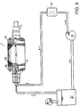
- Fig. 1 shows a molding system using the molding roll for the production of hook elements for touch fastener products.
- the process and basic machine shown are in accordance with the Fischer techniques as described in U.S. Patents 4,775,310, 4,794,028 and 4,872,243, which are hereby incorporated by reference as if they were fully set forth.
- the mold roll 1 has miniature hook form mold cavities around its periphery for forming hook projections on an extruded strip-form touch fastener product 4.
- Mold roll 1 comprises many annular, thin mold rings, for instance of .006 to .020 inch thickness, held together as a stack.
- Heat-softened synthetic resin 5 is forced into the cavities under pressure.
- the hook-form projections at least partially solidify in the mold cavities, and are then pulled out of the cavities in area 8 after the product has cooled to a temperature at which the projections have solidified sufficiently to be pulled intact out of their mold cavities, remaining integral with the base sheet of the product.
- the projections are pulled out of mold roll 1 by passing the product around an idler roll 44, and from there to the takeup assembly 50.
- Fig. 2 illustrates improvements made by the present invention as they relate to mold roll 1 of Fig. 1.
- the transverse load applied to the mold roll by the pressure roll 6 (Fig. 1), or by other means for applying resin under pressure tends to cause mold roll 1 to bend, which can result in uneven product thickness.
- Stiffening mold roll 1 in the manner shown in Fig. 2 facilitates the production of product 4 with a desirably thinner base, and also enables the use of longer mold rolls 1, producing desirably wider products 4.
- the individual mold rings 9 of mold roll 1 are aligned and stacked axially around a common shaft 15. Rings 9 are held together under axial compression by an array of tie rods 16 extending through aligned holes in the stack of rings, running parallel to shaft 15 and tensioned by threaded nuts 17 at each end.
- an array of many coolant passages 22 pass through mold roll 1 near the periphery of mold rings 9 for improved cooling of the mold cavities at the periphery of the mold roll.
- cooling fluid is pumped into the mold roll through an annular inlet 60 in shaft 15, and passes through shaft holes 62 and passages 64 of an inlet manifold 26. From the inlet manifold, the coolant passes through the mold roll along cooling passages 22 to an outlet manifold 25 at the other end of the mold roll, which also has passages 64 to direct the coolant through shaft holes 65 and a return passage 66 in shaft 15, to outlet 68.
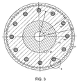
- Fig. 3 is a cross-sectional view of the mold roll 1 of Radius R, showing the arrangement of tie rods 16 around shaft 15.
- a circular array of eight one-inch diameter tie rods within about 2 to 3 inches of the periphery of a roll of radius R of 5.0 inch, on a bolt circle of radius R 2 of 3.8 inch, each tightened to establish substantial preload tension, enable axial compression of the mold roll such as to provide advantageous bending resistance.
- An array of many, relatively small coolant holes 21 are also seen near the periphery of the mold ring at radius R 1 . The coolant holes 21 in each ring are aligned to form the cooling passages 22 extending through the assembled mold roll 1 (Fig. 2).
- an array of about 60 one-quarter inch diameter coolant holes, arrayed on a radius R 1 of about 4.75 inches, provide improved temperature consistency around the mold roll.
- the axial compression of the mold roll by the tensioned tie rods 16 establishes a degree of thermal contact between the faces of the rings and serves to keep liquid coolant within coolant holes 21 from leaking between mold rings 9.
- a key 41 is employed to transfer driving torque from shaft 15 to the stacked mold rings.
- the mold cavities 2 near the periphery of mold roll 1 are shaped to form fastener elements integral to a base sheet. These mold cavities 2 form features of about 0.005 to 0.100 inch in height, and on the order of 0.005 to 0.100 inch wide.
- coolant holes 21 are in close proximity to mold cavities 2, within a distance d of, for instance, 0.2 inch. Also visible in this view is a gap 70 between tie rod 16 and the wall of an associated hole 71 through the mold roll. This gap enables improved mold ring alignment, as will be discussed later.
- mold cavities 21 are formed such that they do not extend through the entire thickness of a mold ring 9.
- mold rings 9 are stacked directly against one another, with the open surface 18 of one ring, for instance ring 9a, against the closed surface 19 of the next ring, for instance ring 9b, which forms a side of the mold cavities in ring 9a.
- mold cavities 21 such that they do not extend through the thickness of mold ring 9 is that they may be used to form features with at least one curved side, formed by a concave surface 20.
- the resulting tapered and convex nature of the hooks can contribute to the penetrability of the hooks into shallow loops, such as presented by non woven fabrics.
- the portion 72 of the mold ring that functions as a spacer between rows of hooks adds thickness to the ring and makes it easier to handle during fabrication and assembly.
- the mold cavities extend through the thickness of the mold rings.
- spacer rings void of mold cavities are stacked between mold rings to enclose the mold cavities that are otherwise defined in the mold rings.
- mold cavities are formed on both sides of some mold rings, the array of mold cavities on the two sides of the ring being circumferentially offset to avoid interference between mold cavities on mating rings.
- a mold cavity for a given feature is formed by accurately aligned cavity portions in two or more mold rings to form a single mold cavity.
- the ring-facing side of exhaust manifold 25 has an inner and an outer recess, 74 and 76, respectively, connected by several radial grooves 78.
- Recesses 74 and 76, and grooves 78 form a hydraulic passage (e.g. 64 in Fig. 2) to hydraulically connect the coolant passages in the mold rings with shaft 15.
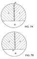
- sealant material 30 is employed to contribute to sealing cooling passages 22 within mold rings 9 in a preferred embodiment. Sealing is augmented by axial compression of the mold roll by the tie rods. In a presently preferred embodiment, sealant 30 is placed along the surfaces of mold rings 9 before assembly, as shown in Fig. 7, and is compressed by the axial compression of the mold roll. In another embodiment (Fig. 7B), the sealant is fluid-deposited, e.g. as carried by automobile radiator repair fluid, by the leakage of coolant into any interstitial space between mold rings 9 near coolant passages 22.
- Sealant material 30 is also placed at each end of the stacked roll of mold rings 9, near the location of tie rods 16 and shaft 15, to seal against leakage from manifolds 25 and 26 (Fig. 2).
- Use of a hydrophobic material as sealant 30 helps to restrict the migration of water-based coolant between the mold rings.
- a thermally conductive material 39 is deposited on the surface of the cooling passages 22, and acts as a sealant to keep the coolant from leaking between mold rings 9.
- This conductive material may be deposited in an electroplating process as shown in Fig. 8 after the mold rings 9 are stacked together and compressed.
- the compressed stack 38 of rings serves as one electrode as electroplating fluid 40 is circulated through the cooling passages 22.
- a layer of plating material e.g. thermally conductive material 39
- Sufficient axial compression of stack 38 during this process, along with an appropriate viscosity of fluid 40 keeps the fluid 40 from migrating between the mold rings, although a small amount of migration of fluid 40 between rings 9 is not adverse to the function of the assembled mold roll.
- seals are also employed as required to maintain the integrity of the cooling system, such as static seals at the interfaces of manifolds 25 and 26 to shaft 15 and to the stack of mold rings, and dynamic seals between the ends of shaft 15 and the stationary plumbing.
- coolant is circulated through the cooling system by a pump 23, and flows into mold roll 1, through inlet manifold 26 in communication with all of the cooling passages 22, along cooling passages 22, through outlet manifold 25, into shaft 15 and back to a cooling reservoir 27.
- the coolant system incorporates a vacuum source 31A and/or other means, including an upstream flow restriction 42, to maintain a subatmospheric pressure within cooling passages 22.
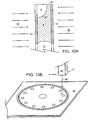
- a photochemical (PC) etching process is used to form mold cavities 2, coolant passages 22, and other features, such as an alignment keyway for key 41 (Fig. 3).
- mold cavities 2 do not extend through the thickness of mold ring 9.
- an etch-resistant photoresist material 31 is fixed to the surfaces of a sheet 82 of mold ring material of the proper thickness and then developed by exposure to ultraviolet light through a mask (not shown) that is cut to produce the desired final surface configuration, including preferably the finished inner and outer diameters of the mold ring.
- the undeveloped photoresist material in areas beneath the mask remains fixed to the sheet as the developed material 31 is removed.
- Etching fluid 32 is then sprayed on the surfaces of the sheet, etching the areas not covered by etch-resistant material 31.
- material 31 is removed from the finished mold ring 9.
- the etching rate is slower at the bottom of the mold cavity, due in part to the dilution of the etching fluid, thus creating a concave surface 20 at the bottom of molding cavity 2, and useful undercuts (not shown) in some arrangements.
- the mold cavities are formed with PC techniques by etching through the thickness of the sheet, either from one side or by etching through both sides.
- An advantage of the PC process is that all of the features on a mold ring 9, including the inner and outer diameters, coolant holes 21 and mold cavities 2, can be advantageously produced at the same time or in an appropriate sequence, using precisely positioned masks in accordance with general photo-lithographic techniques, as employed e.g., in the semiconductor industry.
- one side of a sheet of mold ring stock is appropriately masked to etch all of the features to the depth of the mold cavities 2, and the other side of the sheet is masked by a system that holds registration to complete the etching of the inner and outer diameters and coolant holes 21 through the thickness of mold ring 9.
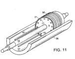
- a laser machining technique is employed in other embodiments to produce mold rings 9 from a sheet 33 of ring stock.
- hook profiles cut through the thickness of sheet 33 are readily formed, and these can be advantageously of smaller size than those previously formed using wire EDM methods. For instance, hook elements as short as 0.005 to 0.008 inch, with appropriately small radii of 0.001 or 0.002 inch, can be formed.
- sheet 33 of the proper thickness is fixtured to be presented to a laser head 34.
- a beam 35 of energy from laser head 34 removes material from sheet 33, according to a programmed pattern, to produce a finished mold ring.
- Head 34 is typically mounted on a positionable base, such that the motion of the head can be controlled as desired to form the features of the finished ring.
- Transverse X-Y motion of a table carrying sheet 33 may also be employed.
- the depth of the groove produced by the effect of the beam 35 on the sheet 33 is a function of the intensity or power of the beam 35, the material properties of the sheet 33, and the speed at which the head 34 or sheet 33 is moved. Varying these parameters can produce the desired depth of the mold cavities, while also cutting through the entire thickness of the sheet to form the coolant holes 21, the holes 71 for the tie rods, and the ring inner and outer diameters.
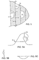
- particularly close control of the deposition of laser energy is maintained to limit the vaporization of the ring material to produce, for example, the general cavity shape of Figs. 5A, 5B and 5C.
- the structure of the mold roll according to the invention enables an improved mold ring alignment method, using a radial alignment shell 36 and one or more orientation bars 37.
- the rings are sequentially stacked about shaft 15 which is concentrically aligned to shell 36 by the inlet and outlet manifolds (i.e., 25) or other means.
- Tie rods 16 or other alignment bars inserted through holes 71
- align holes 71 as rings 9 are stacked, also aligning coolant holes 21 in each ring to form the cooling passages of the assembled roll.
- the inner surface 37 of shell 36 aligns the outer surface of the rings, such that the assembled roll has a very cylindrical circumference for producing an even base thickness in the molded fastener product.
- the stack of rings is concentrically aligned with shaft 15. The gap (70, Fig. 4) between tie rods 16 and the inner edges of holes 71 enables each ring to be radially aligned by surface 37 of shell 36 without radial restraint from tie rods 16. After rings 9 are stacked, the other manifold is set in place and the stack 38 is compressed and removed from alignment shell 36.
- the rings are aligned with an expandable center shaft.
- the invention enables faster production rates and therefore lower unit production costs, more accurately formed products, and products with finer features and higher flexibility of the supporting base layer.
- Fig. 1 In molding machines that employ substantially the Fischer process, other systems from that shown in Fig. 1 may introduce pressurized heat softened or molten synthetic resin to the surface of the mold roll under conditions that fill the mold cavities and form a base layer integral with features molded in the cavities. For instance an extruder may be moved closer to the roll from what is shown in Fig. 1 and the extruder nozzle may confine the resin so that it is applied with pressure directly to the mold roll, filling the cavities and forming a base layer of desired thickness.
- the structure of the mold roll of the invention can advantageously stiffen and align the roll for improved base thickness consistency, enabling the production of thinner bases, and wider products.
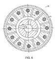
- Figure 12 shows a mold roll according to the invention arranged to make a product with molded fastener elements on one side and engageable loops on the other side, in accordance with the teachings of U.S. 5,260,015 and U.S. 5,518,795, which are hereby incorporated by reference as if fully set forth herein.
- Figure 13 shows mold rolls according to the invention employed in making a so called back-to-back product in accordance with the teachings of WO 94/07556, which is hereby incorporated by reference as if fully set forth herein.
- both mold roll 1 and pressure roll 46 are constructed and cooled in accordance with the invention.
- both rolls have mold cavities to form features on the finished product.
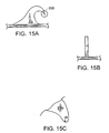
- Figs. 15A and 15B Shown in Figs. 15A and 15B is a fine, sharp tip fastener element formed with mold plates fabricated by the laser machining process illustrated in Fig. 10B.
- Elements with tips having radii, R (Fig. 15C), of about 0.001 inch or less (preferably only about 0.0005 inch), are obtainable with laser-machined molds.
- Certain advantages are provided by sharp tip fastener elements including penetrability into the loops of engaging loop materials. The sharp tip enables penetration between an engageable loop and the rest of the loop mass of a looped fastener member.
- Improving the loop-engaging probability of an individual hook of a hook fastener member increases the engagement ratio of an array of hooks, that is, the overall percentage of hooks of the array that, at any given time, engage loops. Higher engagement ratios typically result in better fastener performance.
- the laser machining process enables the formation of mold surfaces 20 that do not extend through the entire thickness of mold plate 9.
- An advantage of forming mold surfaces that do not extend through the mold plate is that they may be used to form fastener elements with at least one convex surface which may contribute to the penetrability of the elements into shallow loops, such as those presented by non-woven fabrics.
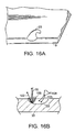
- particularly close control of the deposition of laser energy is maintained by appropriate machine controls to limit the vaporization of the plate material to produce, for example, the concave mold surface 20 shown in Figs. 16A and 16B.
- the depth of the laser cut produced by the effect of beam 35 on sheet 33 is a function of the intensity or power of beam 35, the material properties of sheet 33, and the speed at which the laser head or sheet 33 is moved. Varying these parameters can produce either a concave mold surface of a desired depth (Fig. 16A) or can cut through the entire thickness of the sheet to form mold cavities and/or cooling holes or plate inner and outer diameters.
- a concave mold surface of a desired depth Fig. 16A
- hot molten debris 106 of plate material is produced.
- a blower 108 is employed to maintain an air flow 105 sufficient to continually displace debris 106 from the forming area in the general direction indicated by arrow 102. This is especially important when forming concave surfaces not extending through the plate, as in Fig. 16B.
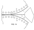
- Fig. 17A shows a mold cavity 90 formed by stacking a mold plate 9a with the laser machined surface 20 of Fig. 16A against the flat side of a spacer plate 9b. Similar cavities are also formed by stacking mold plates 9a' and 9a'' together, such that their mold surfaces 20 do not overlap. This arrangement can be used to produce fastener products with particularly high densities.
- a mold cavity for a given feature is formed by accurately aligned and cooperating mold surfaces 118 and 120 in two adjacent mold plates 9c and 9d, respectively, to form a single mold cavity 114.
- mold surfaces can be cut through the thickness of a mold plate at speeds of up to one circumferential inch per minute.
- a finished mold plate can typically be machined in less than one hour.
- a pulsed laser is preferred.
- the laser-machined mold plates are immersed in a chemical etchant which preferentially removes mold plate material of the microscopic asperities left by the laser-machining process. Finished mold surfaces with a roughness of 63 microinches, for instance, have been found to acceptably release molded fastener elements.
Landscapes
- Engineering & Computer Science (AREA)
- Mechanical Engineering (AREA)
- Textile Engineering (AREA)
- Physics & Mathematics (AREA)
- Thermal Sciences (AREA)
- General Engineering & Computer Science (AREA)
- Moulds For Moulding Plastics Or The Like (AREA)
Claims (16)
- Verfahren zur Herstellung einer Form (2), umfassend formende Formplatten (9) aus einem Vorrat einer flachen Platte, beinhaltend für die Formplatten ein Ausbilden eines Arrays bzw. Felds von Formoberflächen (20), welche sich nach innen von den Formplatten (9) erstrecken;
gekennzeichnet durch
ein Laserschneiden jeder Platte (9), um das Feld von Formoberflächen (20) an einer offenen Oberfläche (18) an einer Seite der Formplatte (9) auszubilden; und
ein Konfigurieren der Formoberflächen (20), so daß die Formoberflächen (20) als Festlegungselement geformte Hohlräume bzw. Ausnehmungen (2) definieren. - Verfahren nach Anspruch 1 zum Formen eines Festlegungsprodukts (4), das Reihen von Festlegungselementen integral mit einer Basis aufweist, wobei das Verfahren weiters gekennzeichnet ist durch ein Stapeln der Formplatten (9), wobei ihre Kanten ausgerichtet werden, um eine Oberfläche einer Form auszubilden, die Reihen von festlegungselement-förmigen Formhohlräumen (2) aufweist; und/oder beinhaltend den Schritt eines Laserschneidens von Kühllöchern (21) durch die Dicke der Platten (9) an Orten, die von ihren Kanten beabstandet sind; und/oder beinhaltend den Schritt eines Ausrichtens der Löcher (21) während des Stapelns, um Kühldurchgänge (22) auszubilden; und/oder wobei die Formplatten (9) rund sind und der Schritt eines Ausbildens ein Laserschneiden der Außenkanten der Formplatten (9) beinhaltend.
- Verfahren nach Anspruch 2, wobei die gestapelten Platten (9) ein Teil einer Form bilden, die konstruiert wird, um zum Spritzgießen eines Produkts und zum Entfernen des spritzgegossenen Produkts geschlossen und geöffnet zu werden.
- Verfahren nach Anspruch 2, wobei der Schritt eines Stapelns ein axiales Stapeln von runden Formplatten (9) beinhaltet, um eine Formwalze (1) zu bilden.
- Verfahren nach Anspruch 4, weiters umfassend einen Einlaßverteiler (26), der an einem ersten Ende der Formwalze (1) festgelegt wird, um Kühlflüssigkeit in Kühldurchtritte (22) durch die Platten (9) zu richten; und/oder wobei die Formwalze (1) weiters einen Rückkehrdurchgang (66) umfaßt, der mit den Kühldurchgängen (22) durch die Platten (9) kommuniziert bzw. in Verbindung steht und sich axial durch die Walze (1) erstreckt.
- Verfahren nach Anspruch 4 oder 5, wobei eine große Anzahl von Kühldurchtritten (22) in einem Kreis benachbart dem Umfang der Formwalze (1) angeordnet wird; und/oder wobei die Formwalze (1) einen Durchmesser zwischen etwa 8 bis 12 Zoll aufweist und wenigstens 50 Kühldurchtritte (22) innerhalb etwa eines halben Zolls von dem Umfang der Walze (1) angeordnet werden.
- Verfahren nach einem der Ansprüche 2-6, beinhaltend Mittel (31), um einen subatmosphärischen Druck auf das Kühlfluid in den Durchgängen (22) aufrechtzuerhalten.
- Verfahren nach einem der Ansprüche 2-7, weiters umfassend ein Dichtmaterial (30; 39) in der Nachbarschaft der Kühllöcher (21), um ein Dichten zu unterstützen; und/oder wobei die Platten (9) an ihren Seiten benachbart den Kühllöchern (21) mit Dichtmaterial (39) beschichtet werden; und/oder wobei das Dichtmaterial (30) in Abstände zwischen den Platten (9) durch Fluid abgeschieden wird.
- Verfahren nach Anspruch 4, weiters umfassend ein Komprimieren des Stapels unter Verwendung eines Umfangfelds von Zugstangen (16), die sich durch die Platten (9) parallel zu einer Welle (15) erstrecken und einen axialen Kompressionsdruck auf die Platten (9) ausüben; und/oder wobei die Formwalze (1) einen Durchmesser in der Größenordnung von 8 bis 12 Zoll aufweist und wenigstens 6 Zugstangen (16) innerhalb von etwa 2 Zoll vom Umfang der Walze (1) angeordnet werden.
- Verfahren nach Anspruch 4, wobei ein axiales Stapeln von runden Formplatten (9) zum Ausbilden einer Formwalze (1) ein Bereitstellen einer Ausrichtungshülle (36) beinhaltet, die eine kreisförmige Ausrichtungs-Oberfläche (37) definiert und jeden Ring (9) an seiner Außenumfangs-Oberfläche durch die Ausrichtungs-Oberfläche (37) abstützt.
- Verfahren nach Anspruch 1, wobei der Schritt des Laserschneidens ein Schneiden von Formoberflächen (20) beinhaltet, welche Befestigungselement-Merkmale definieren, die Endradien (R) von weniger als etwa 0,001 Zoll, vorzugsweise weniger als etwa 0,0005 Zoll aufweisen; und/oder beinhaltend ein Ausbilden von wenigstens einigen der festlegungselement-förmigen Formhohlräume (2) durch die Formoberflächen (118, 120) von zwei oder mehreren benachbarten gestapelten Formplatten (9); und/oder beinhaltend ein Steuern bzw. Regeln des Laserschneidens, um Formoberflächen (20) herzustellen, die sich durch nur einen Abschnitt der Dicke ihrer entsprechenden Formplatten (9) erstrecken; und/oder wobei der Schritt eines Ausbildens ein Laserschneiden von wenigstens einigen der Formoberflächen (20; 118, 120) beinhaltet, welche sich durch ihre entsprechenden Formplatten (9) erstrecken; und/oder wobei die Formoberflächen gleichzeitig durch ein Laserschneiden in einer Mehrzahl von Formplatten (9) ausgebildet werden; und/oder wobei der Schritt eines Ausbildens nach einem Laserschneiden der Formoberflächen (20) ein Glätten der Formoberflächen beinhaltet; und/oder wobei die Formplatten (9) in ein chemisches Ätzmittel eingetaucht werden, um die Formoberflächen (20) zu glätten.
- Formplatte (9), geformt aus einem Vorrat einer ebenen Platte, der ein Array bzw. Feld von Formoberflächen (20) aufweist,
dadurch gekennzeichnet, daß
das Feld von Formoberflächen (20) in eine offene Oberfläche (18) an einer Seite der Formplatte (9) derartig lasergeschnitten ist, daß, wenn die Formplatte (9a, 9a') gegen eine ebene Abstandshalterplatte (9b) oder eine zweite Formplatte (9a") gestapelt ist, die Formoberfläche (20) festlegungselementförmige Hohlräume definiert. - Formplatte nach Anspruch 12, die eine Dicke von weniger als etwa 0,020 Zoll aufweist; und/oder umfassend konkave Formoberflächen (20), die sich durch nur einen Abschnitt der Dicke der Formplatte (9) erstrecken; und/oder umfassend Formoberflächen, die sich vollständig durch die Dicke der Formplatte (9) erstrecken.
- Formplatte nach Anspruch 12, die Kühlmittellöcher (21) aufweist, die sich durch ihre Dicke erstrecken.
- Formplatte nach Anspruch 14, die lasergeschnittene Kühllöcher (21) an Orten aufweist, die von ihrer Kante beabstandet sind, wobei sich die Formoberflächen (20) und Kühllöcher (21) vollständig durch die Dicke der Formplatte (9) erstrecken.
- Formplatte nach Anspruch 14, wobei die Kühllöcher lasergeschnitten sind.
Applications Claiming Priority (5)
| Application Number | Priority Date | Filing Date | Title |
|---|---|---|---|
| US786226 | 1997-01-21 | ||
| US08/786,226 US5971738A (en) | 1997-01-21 | 1997-01-21 | Continuous molding of fasteners and other features |
| US08/926,517 US6039556A (en) | 1997-01-21 | 1997-09-10 | Stackable mold plates having arrays of laser-cut mold surfaces at their edges |
| US926517 | 1997-09-10 | ||
| PCT/US1998/001053 WO1998031520A1 (en) | 1997-01-21 | 1998-01-20 | Molding of fasteners and other features |
Publications (3)
| Publication Number | Publication Date |
|---|---|
| EP1019229A1 EP1019229A1 (de) | 2000-07-19 |
| EP1019229A4 EP1019229A4 (de) | 2001-07-04 |
| EP1019229B1 true EP1019229B1 (de) | 2005-07-27 |
Family
ID=27120518
Family Applications (1)
| Application Number | Title | Priority Date | Filing Date |
|---|---|---|---|
| EP98904603A Expired - Lifetime EP1019229B1 (de) | 1997-01-21 | 1998-01-20 | Verfahren zur herstellung einer form aus formplatten und eine formplatte hergestellt aus einer flachen platte |
Country Status (6)
| Country | Link |
|---|---|
| US (2) | US6039556A (de) |
| EP (1) | EP1019229B1 (de) |
| AU (1) | AU6244298A (de) |
| DE (1) | DE69831004T2 (de) |
| ES (1) | ES2245021T3 (de) |
| WO (1) | WO1998031520A1 (de) |
Families Citing this family (29)
| Publication number | Priority date | Publication date | Assignee | Title |
|---|---|---|---|---|
| US5900350A (en) * | 1996-06-06 | 1999-05-04 | Velcro Industries B.V. | Molding methods, molds and products |
| US6039556A (en) * | 1997-01-21 | 2000-03-21 | Velcro Industries B.V. | Stackable mold plates having arrays of laser-cut mold surfaces at their edges |
| US6930277B2 (en) * | 1997-09-10 | 2005-08-16 | Velcro Industries B.V. | Fastener element molding |
| US5884374A (en) * | 1997-11-20 | 1999-03-23 | Velcro Industries B.V. | Fastener members and apparatus for their fabrication |
| DE29800426U1 (de) * | 1998-01-14 | 1998-06-10 | Walter Watermann | Kühl- und Heizkern |
| US6162040A (en) * | 1999-02-01 | 2000-12-19 | Velcro Industries B.V. | Molds for forming touch fasteners |
| US6190594B1 (en) | 1999-03-01 | 2001-02-20 | 3M Innovative Properties Company | Tooling for articles with structured surfaces |
| WO2002098624A1 (en) | 2001-06-05 | 2002-12-12 | Mikro Systems Inc. | Methods for manufacturing three-dimensional devices and devices created thereby |
| US7785098B1 (en) | 2001-06-05 | 2010-08-31 | Mikro Systems, Inc. | Systems for large area micro mechanical systems |
| WO2003094323A1 (en) * | 2002-05-06 | 2003-11-13 | Aerovironment, Inc. | Lamination cooling system |
| US6902389B2 (en) | 2003-05-14 | 2005-06-07 | 3M Innovative Properties Company | Wire wound tooling |
| US20050244756A1 (en) * | 2004-04-30 | 2005-11-03 | Clarner Mark A | Etch rate control |
| US7192266B2 (en) * | 2004-09-28 | 2007-03-20 | Velera Industries | Molding device inserts |
| US7641469B2 (en) * | 2004-09-28 | 2010-01-05 | Velcro Industries B.V. | Fastener molding |
| US7217119B2 (en) * | 2005-05-18 | 2007-05-15 | Velcro Industries B.V. | Fastener molding |
| US7806677B2 (en) | 2007-07-16 | 2010-10-05 | Velcro Industries B.V. | Molding apparatus and related systems and methods |
| FR2922805B1 (fr) | 2007-10-26 | 2013-09-06 | Aplix Sa | Bloc d'insertion pour la formation d'un champ de crochets sur un objet moule par injection et objet moule comportant un champ de crochet de ce genre |
| US9315663B2 (en) * | 2008-09-26 | 2016-04-19 | Mikro Systems, Inc. | Systems, devices, and/or methods for manufacturing castings |
| CN102458559B (zh) | 2009-04-10 | 2014-06-04 | 3M创新有限公司 | 制造中空微针阵列的方法以及由其制得的制品和用途 |
| CN101992546B (zh) * | 2010-09-26 | 2013-05-15 | 常州丰盛光电科技股份有限公司 | 用于微结构复制的分区温控辊筒 |
| US8813824B2 (en) | 2011-12-06 | 2014-08-26 | Mikro Systems, Inc. | Systems, devices, and/or methods for producing holes |
| DE102012106527B4 (de) * | 2012-07-18 | 2016-01-21 | Maschinenfabrik Köppern GmbH & Co KG | Presswalze für eine Walzenpresse |
| FR2998628B1 (fr) * | 2012-11-28 | 2015-01-16 | Aplix Sa | Elements d accrochage moules et leur procede de fabrication |
| US10189186B2 (en) | 2014-05-16 | 2019-01-29 | Ford Global Technologies, Llc | Method for finishing matching surfaces in forming tool components |
| CN104309038B (zh) * | 2014-09-01 | 2016-09-14 | 余祥艮 | 一种高速流延辊的端盖结构 |
| CN110868883B (zh) | 2017-07-11 | 2022-12-13 | 维克罗知识产权控股有限责任公司 | 形成紧固件元件 |
| SG11202004522RA (en) * | 2017-11-27 | 2020-06-29 | Essentium Inc | Tool assembly for manufacturing parts and a method of producing a tooling assembly |
| JP2023504899A (ja) | 2019-12-09 | 2023-02-07 | スリーエム イノベイティブ プロパティズ カンパニー | 共押出ポリマー物品及びその製造方法 |
| US20230182348A1 (en) * | 2020-05-01 | 2023-06-15 | Essentium Ipco, Llc | Tool assembly for manufacturing parts and a method of producing a tool assembly |
Family Cites Families (30)
| Publication number | Priority date | Publication date | Assignee | Title |
|---|---|---|---|---|
| US973380A (en) * | 1910-01-20 | 1910-10-18 | Improved Paper Machinery Company | Method of making press-rolls. |
| US3031730A (en) | 1958-09-26 | 1962-05-01 | Louis H Morin | Burr-type closure or coupling element |
| US3027595A (en) * | 1959-11-27 | 1962-04-03 | Takai Unokichi | Apparatus and method of continuous molding of a thermoplastic sheet having fine pile-like projections |
| US3136026A (en) | 1960-06-23 | 1964-06-09 | Velcro Sa Soulie | Method for producing a device for joining two flexibel elements |
| US3089191A (en) * | 1961-06-13 | 1963-05-14 | American Pipe & Constr Co | Product method and apparatus for making a hobbed-surfaced sheet material |
| US3261069A (en) | 1963-06-04 | 1966-07-19 | Robert V Mathison | Fasteners and articles employing same |
| US3312583A (en) * | 1963-10-02 | 1967-04-04 | James J Rochlis | Apertured and staggered molded pile product |
| US3555601A (en) * | 1968-07-30 | 1971-01-19 | Harold Price | Apparatus for continuously forming conical shaped cleats on a thermoplastic sheet |
| US3752619A (en) * | 1971-11-11 | 1973-08-14 | American Velcro Inc | Production of a continuous molded plastic strip |
| US3907486A (en) * | 1973-12-07 | 1975-09-23 | United States Steel Corp | Means for internally cooling briquetting machine rolls and segments |
| US4261692A (en) * | 1979-11-01 | 1981-04-14 | Davy Mckee Corporation | Roll press for forming briquettes |
| US4573893A (en) * | 1984-04-02 | 1986-03-04 | Application Engineering Corporation | Extrusion die with external and internal cooling means |
| US4872243A (en) | 1984-04-16 | 1989-10-10 | Velcro Industries B.V. | Multi-hook fastener member |
| US4775310A (en) * | 1984-04-16 | 1988-10-04 | Velcro Industries B.V. | Apparatus for making a separable fastener |
| US4794028A (en) * | 1984-04-16 | 1988-12-27 | Velcro Industries B.V. | Method for continuously producing a multi-hook fastner member and product of the method |
| US4587700A (en) * | 1984-06-08 | 1986-05-13 | The Garrett Corporation | Method for manufacturing a dual alloy cooled turbine wheel |
| US4725221A (en) * | 1986-05-23 | 1988-02-16 | John H. Blanz Company, Inc. | Improved machine for continuously producing an element of a separable fastener |
| US5174937A (en) * | 1987-09-05 | 1992-12-29 | Canon Kabushiki Kaisha | Method for molding of substrate for information recording medium and method for preparing substrate for information recording medium |
| US4894060A (en) | 1988-01-11 | 1990-01-16 | Minnesota Mining And Manufacturing Company | Disposable diaper with improved hook fastener portion |
| US4984339A (en) | 1988-10-20 | 1991-01-15 | Velcro Industries B.V. | Hook for hook and loop fasteners |
| KR930006066B1 (ko) * | 1989-08-22 | 1993-07-03 | 가부시기가이샤 마쓰다 세이사꾸쇼 | 다공로울장치 및 그 제조방법 |
| JPH0431512U (de) | 1990-07-03 | 1992-03-13 | ||
| US5326612A (en) | 1991-05-20 | 1994-07-05 | The Procter & Gamble Company | Nonwoven female component for refastenable fastening device and method of making the same |
| JPH0584213U (ja) | 1992-04-24 | 1993-11-16 | 吉田工業株式会社 | 一体成形面ファスナー |
| US5339499A (en) | 1993-02-16 | 1994-08-23 | Velcro Industries B.V. | Hook design for a hook and loop fastener |
| WO1994029070A1 (en) | 1993-06-11 | 1994-12-22 | Minnesota Mining And Manufacturing Company | Laser machined replication tooling |
| WO1995001863A1 (en) * | 1993-07-06 | 1995-01-19 | Velcro Industries, B.V. | Back-to-back hook fastener |
| JP3471954B2 (ja) * | 1994-03-10 | 2003-12-02 | キヤノン株式会社 | プラスチック成形品及びその成形方法 |
| US6039556A (en) * | 1997-01-21 | 2000-03-21 | Velcro Industries B.V. | Stackable mold plates having arrays of laser-cut mold surfaces at their edges |
| US5971738A (en) * | 1997-01-21 | 1999-10-26 | Velcro Industries B.V. | Continuous molding of fasteners and other features |
-
1997
- 1997-09-10 US US08/926,517 patent/US6039556A/en not_active Expired - Lifetime
-
1998
- 1998-01-20 EP EP98904603A patent/EP1019229B1/de not_active Expired - Lifetime
- 1998-01-20 ES ES98904603T patent/ES2245021T3/es not_active Expired - Lifetime
- 1998-01-20 AU AU62442/98A patent/AU6244298A/en not_active Abandoned
- 1998-01-20 WO PCT/US1998/001053 patent/WO1998031520A1/en not_active Ceased
- 1998-01-20 DE DE69831004T patent/DE69831004T2/de not_active Expired - Lifetime
-
2002
- 2002-05-08 US US09/341,908 patent/US6533981B1/en not_active Expired - Fee Related
Also Published As
| Publication number | Publication date |
|---|---|
| EP1019229A4 (de) | 2001-07-04 |
| US6533981B1 (en) | 2003-03-18 |
| DE69831004T2 (de) | 2006-06-01 |
| DE69831004D1 (de) | 2005-09-01 |
| US6039556A (en) | 2000-03-21 |
| AU6244298A (en) | 1998-08-07 |
| ES2245021T3 (es) | 2005-12-16 |
| EP1019229A1 (de) | 2000-07-19 |
| WO1998031520A1 (en) | 1998-07-23 |
Similar Documents
| Publication | Publication Date | Title |
|---|---|---|
| EP1019229B1 (de) | Verfahren zur herstellung einer form aus formplatten und eine formplatte hergestellt aus einer flachen platte | |
| US5971738A (en) | Continuous molding of fasteners and other features | |
| US6258311B1 (en) | Forming mold cavities | |
| US6099289A (en) | Forming mold cavities | |
| US5900350A (en) | Molding methods, molds and products | |
| AU754541B2 (en) | Process and apparatus for making papermaking belt using fluid pressure differential | |
| US6930277B2 (en) | Fastener element molding | |
| KR0152167B1 (ko) | 면파스너 제조 방법 및 장치 | |
| EP2117980A2 (de) | Bandgewickelte rolle | |
| EP1017553B1 (de) | Herstellen von formvertiefungen | |
| CN1754673B (zh) | 成型装置嵌件 | |
| AU2916002A (en) | Molding of fastening hooks and other devices |
Legal Events
| Date | Code | Title | Description |
|---|---|---|---|
| PUAI | Public reference made under article 153(3) epc to a published international application that has entered the european phase |
Free format text: ORIGINAL CODE: 0009012 |
|
| 17P | Request for examination filed |
Effective date: 19990820 |
|
| AK | Designated contracting states |
Kind code of ref document: A1 Designated state(s): DE ES FR GB IT |
|
| A4 | Supplementary search report drawn up and despatched |
Effective date: 20010521 |
|
| AK | Designated contracting states |
Kind code of ref document: A4 Designated state(s): DE ES FR GB IT |
|
| RIC1 | Information provided on ipc code assigned before grant |
Free format text: 7B 29C 33/02 A, 7B 29C 39/18 B, 7B 29C 39/26 B, 7B 29C 39/38 B, 7B 29C 43/28 B, 7B 29C 43/46 B, 7B 29C 43/52 B, 7B 29C 43/22 B, 7A 44B 18/00 B, 7B 29C 33/30 B, 7B 29C 33/38 B |
|
| 17Q | First examination report despatched |
Effective date: 20031029 |
|
| GRAP | Despatch of communication of intention to grant a patent |
Free format text: ORIGINAL CODE: EPIDOSNIGR1 |
|
| RTI1 | Title (correction) |
Free format text: METHOD OF MAKING A MOULD FROM MOULD PLATES AND A MOULD PLATE FORMED FROM FLAT PLATE STOCK |
|
| GRAS | Grant fee paid |
Free format text: ORIGINAL CODE: EPIDOSNIGR3 |
|
| GRAA | (expected) grant |
Free format text: ORIGINAL CODE: 0009210 |
|
| AK | Designated contracting states |
Kind code of ref document: B1 Designated state(s): DE ES FR GB IT |
|
| PG25 | Lapsed in a contracting state [announced via postgrant information from national office to epo] |
Ref country code: IT Free format text: LAPSE BECAUSE OF FAILURE TO SUBMIT A TRANSLATION OF THE DESCRIPTION OR TO PAY THE FEE WITHIN THE PRESCRIBED TIME-LIMIT;WARNING: LAPSES OF ITALIAN PATENTS WITH EFFECTIVE DATE BEFORE 2007 MAY HAVE OCCURRED AT ANY TIME BEFORE 2007. THE CORRECT EFFECTIVE DATE MAY BE DIFFERENT FROM THE ONE RECORDED. Effective date: 20050727 |
|
| REG | Reference to a national code |
Ref country code: GB Ref legal event code: FG4D |
|
| REF | Corresponds to: |
Ref document number: 69831004 Country of ref document: DE Date of ref document: 20050901 Kind code of ref document: P |
|
| REG | Reference to a national code |
Ref country code: ES Ref legal event code: FG2A Ref document number: 2245021 Country of ref document: ES Kind code of ref document: T3 |
|
| PG25 | Lapsed in a contracting state [announced via postgrant information from national office to epo] |
Ref country code: FR Free format text: LAPSE BECAUSE OF NON-PAYMENT OF DUE FEES Effective date: 20060131 |
|
| ET | Fr: translation filed | ||
| PLBE | No opposition filed within time limit |
Free format text: ORIGINAL CODE: 0009261 |
|
| STAA | Information on the status of an ep patent application or granted ep patent |
Free format text: STATUS: NO OPPOSITION FILED WITHIN TIME LIMIT |
|
| 26N | No opposition filed |
Effective date: 20060428 |
|
| REG | Reference to a national code |
Ref country code: FR Ref legal event code: ST Effective date: 20060929 |
|
| PGFP | Annual fee paid to national office [announced via postgrant information from national office to epo] |
Ref country code: ES Payment date: 20090126 Year of fee payment: 12 |
|
| PGFP | Annual fee paid to national office [announced via postgrant information from national office to epo] |
Ref country code: GB Payment date: 20090129 Year of fee payment: 12 |
|
| GBPC | Gb: european patent ceased through non-payment of renewal fee |
Effective date: 20100120 |
|
| PG25 | Lapsed in a contracting state [announced via postgrant information from national office to epo] |
Ref country code: GB Free format text: LAPSE BECAUSE OF NON-PAYMENT OF DUE FEES Effective date: 20100120 |
|
| REG | Reference to a national code |
Ref country code: ES Ref legal event code: FD2A Effective date: 20110330 |
|
| PG25 | Lapsed in a contracting state [announced via postgrant information from national office to epo] |
Ref country code: ES Free format text: LAPSE BECAUSE OF NON-PAYMENT OF DUE FEES Effective date: 20110317 |
|
| PG25 | Lapsed in a contracting state [announced via postgrant information from national office to epo] |
Ref country code: ES Free format text: LAPSE BECAUSE OF NON-PAYMENT OF DUE FEES Effective date: 20100121 |
|
| REG | Reference to a national code |
Ref country code: DE Ref legal event code: R082 Ref document number: 69831004 Country of ref document: DE Representative=s name: MUELLER-BORE & PARTNER PATENTANWAELTE PARTG MB, DE Ref country code: DE Ref legal event code: R081 Ref document number: 69831004 Country of ref document: DE Owner name: VELCRO BVBA, BE Free format text: FORMER OWNER: VELCRO INDUSTRIES B.V., CURACAO, AN |
|
| PGFP | Annual fee paid to national office [announced via postgrant information from national office to epo] |
Ref country code: DE Payment date: 20170125 Year of fee payment: 20 |
|
| REG | Reference to a national code |
Ref country code: DE Ref legal event code: R071 Ref document number: 69831004 Country of ref document: DE |