EP1019200B1 - Hollow vibrational horn - Google Patents
Hollow vibrational horn Download PDFInfo
- Publication number
- EP1019200B1 EP1019200B1 EP98904863A EP98904863A EP1019200B1 EP 1019200 B1 EP1019200 B1 EP 1019200B1 EP 98904863 A EP98904863 A EP 98904863A EP 98904863 A EP98904863 A EP 98904863A EP 1019200 B1 EP1019200 B1 EP 1019200B1
- Authority
- EP
- European Patent Office
- Prior art keywords
- horn
- cylinder
- shaft
- welding
- input end
- Prior art date
- Legal status (The legal status is an assumption and is not a legal conclusion. Google has not performed a legal analysis and makes no representation as to the accuracy of the status listed.)
- Expired - Lifetime
Links
- 238000003466 welding Methods 0.000 claims abstract description 57
- 230000033001 locomotion Effects 0.000 claims description 14
- 239000000463 material Substances 0.000 claims description 14
- 238000006073 displacement reaction Methods 0.000 claims description 11
- 238000000034 method Methods 0.000 description 10
- 230000008569 process Effects 0.000 description 10
- 238000013461 design Methods 0.000 description 8
- 238000004519 manufacturing process Methods 0.000 description 5
- 238000012986 modification Methods 0.000 description 5
- 230000004048 modification Effects 0.000 description 5
- 235000012773 waffles Nutrition 0.000 description 3
- XAGFODPZIPBFFR-UHFFFAOYSA-N aluminium Chemical compound [Al] XAGFODPZIPBFFR-UHFFFAOYSA-N 0.000 description 2
- 229910052782 aluminium Inorganic materials 0.000 description 2
- 238000011161 development Methods 0.000 description 2
- 230000018109 developmental process Effects 0.000 description 2
- 210000004709 eyebrow Anatomy 0.000 description 2
- 238000003754 machining Methods 0.000 description 2
- 230000002093 peripheral effect Effects 0.000 description 2
- 229910000831 Steel Inorganic materials 0.000 description 1
- RTAQQCXQSZGOHL-UHFFFAOYSA-N Titanium Chemical compound [Ti] RTAQQCXQSZGOHL-UHFFFAOYSA-N 0.000 description 1
- 238000005452 bending Methods 0.000 description 1
- 230000008901 benefit Effects 0.000 description 1
- 230000008859 change Effects 0.000 description 1
- 230000006835 compression Effects 0.000 description 1
- 238000007906 compression Methods 0.000 description 1
- 238000005520 cutting process Methods 0.000 description 1
- 230000005284 excitation Effects 0.000 description 1
- 238000010438 heat treatment Methods 0.000 description 1
- 238000012423 maintenance Methods 0.000 description 1
- 238000005259 measurement Methods 0.000 description 1
- 239000002991 molded plastic Substances 0.000 description 1
- 239000004033 plastic Substances 0.000 description 1
- 239000002985 plastic film Substances 0.000 description 1
- 229920006255 plastic film Polymers 0.000 description 1
- 230000002028 premature Effects 0.000 description 1
- 238000007789 sealing Methods 0.000 description 1
- 239000010959 steel Substances 0.000 description 1
- 239000000758 substrate Substances 0.000 description 1
- 238000012360 testing method Methods 0.000 description 1
- 229910052719 titanium Inorganic materials 0.000 description 1
- 239000010936 titanium Substances 0.000 description 1
Images


Classifications
-
- B—PERFORMING OPERATIONS; TRANSPORTING
- B06—GENERATING OR TRANSMITTING MECHANICAL VIBRATIONS IN GENERAL
- B06B—METHODS OR APPARATUS FOR GENERATING OR TRANSMITTING MECHANICAL VIBRATIONS OF INFRASONIC, SONIC, OR ULTRASONIC FREQUENCY, e.g. FOR PERFORMING MECHANICAL WORK IN GENERAL
- B06B3/00—Methods or apparatus specially adapted for transmitting mechanical vibrations of infrasonic, sonic, or ultrasonic frequency
-
- B—PERFORMING OPERATIONS; TRANSPORTING
- B29—WORKING OF PLASTICS; WORKING OF SUBSTANCES IN A PLASTIC STATE IN GENERAL
- B29C—SHAPING OR JOINING OF PLASTICS; SHAPING OF MATERIAL IN A PLASTIC STATE, NOT OTHERWISE PROVIDED FOR; AFTER-TREATMENT OF THE SHAPED PRODUCTS, e.g. REPAIRING
- B29C65/00—Joining or sealing of preformed parts, e.g. welding of plastics materials; Apparatus therefor
- B29C65/02—Joining or sealing of preformed parts, e.g. welding of plastics materials; Apparatus therefor by heating, with or without pressure
- B29C65/08—Joining or sealing of preformed parts, e.g. welding of plastics materials; Apparatus therefor by heating, with or without pressure using ultrasonic vibrations
-
- B—PERFORMING OPERATIONS; TRANSPORTING
- B29—WORKING OF PLASTICS; WORKING OF SUBSTANCES IN A PLASTIC STATE IN GENERAL
- B29C—SHAPING OR JOINING OF PLASTICS; SHAPING OF MATERIAL IN A PLASTIC STATE, NOT OTHERWISE PROVIDED FOR; AFTER-TREATMENT OF THE SHAPED PRODUCTS, e.g. REPAIRING
- B29C66/00—General aspects of processes or apparatus for joining preformed parts
- B29C66/80—General aspects of machine operations or constructions and parts thereof
- B29C66/81—General aspects of the pressing elements, i.e. the elements applying pressure on the parts to be joined in the area to be joined, e.g. the welding jaws or clamps
- B29C66/814—General aspects of the pressing elements, i.e. the elements applying pressure on the parts to be joined in the area to be joined, e.g. the welding jaws or clamps characterised by the design of the pressing elements, e.g. of the welding jaws or clamps
- B29C66/8141—General aspects of the pressing elements, i.e. the elements applying pressure on the parts to be joined in the area to be joined, e.g. the welding jaws or clamps characterised by the design of the pressing elements, e.g. of the welding jaws or clamps characterised by the surface geometry of the part of the pressing elements, e.g. welding jaws or clamps, coming into contact with the parts to be joined
- B29C66/81427—General aspects of the pressing elements, i.e. the elements applying pressure on the parts to be joined in the area to be joined, e.g. the welding jaws or clamps characterised by the design of the pressing elements, e.g. of the welding jaws or clamps characterised by the surface geometry of the part of the pressing elements, e.g. welding jaws or clamps, coming into contact with the parts to be joined comprising a single ridge, e.g. for making a weakening line; comprising a single tooth
-
- B—PERFORMING OPERATIONS; TRANSPORTING
- B29—WORKING OF PLASTICS; WORKING OF SUBSTANCES IN A PLASTIC STATE IN GENERAL
- B29C—SHAPING OR JOINING OF PLASTICS; SHAPING OF MATERIAL IN A PLASTIC STATE, NOT OTHERWISE PROVIDED FOR; AFTER-TREATMENT OF THE SHAPED PRODUCTS, e.g. REPAIRING
- B29C66/00—General aspects of processes or apparatus for joining preformed parts
- B29C66/80—General aspects of machine operations or constructions and parts thereof
- B29C66/81—General aspects of the pressing elements, i.e. the elements applying pressure on the parts to be joined in the area to be joined, e.g. the welding jaws or clamps
- B29C66/814—General aspects of the pressing elements, i.e. the elements applying pressure on the parts to be joined in the area to be joined, e.g. the welding jaws or clamps characterised by the design of the pressing elements, e.g. of the welding jaws or clamps
- B29C66/8141—General aspects of the pressing elements, i.e. the elements applying pressure on the parts to be joined in the area to be joined, e.g. the welding jaws or clamps characterised by the design of the pressing elements, e.g. of the welding jaws or clamps characterised by the surface geometry of the part of the pressing elements, e.g. welding jaws or clamps, coming into contact with the parts to be joined
- B29C66/81431—General aspects of the pressing elements, i.e. the elements applying pressure on the parts to be joined in the area to be joined, e.g. the welding jaws or clamps characterised by the design of the pressing elements, e.g. of the welding jaws or clamps characterised by the surface geometry of the part of the pressing elements, e.g. welding jaws or clamps, coming into contact with the parts to be joined comprising a single cavity, e.g. a groove
-
- B—PERFORMING OPERATIONS; TRANSPORTING
- B29—WORKING OF PLASTICS; WORKING OF SUBSTANCES IN A PLASTIC STATE IN GENERAL
- B29C—SHAPING OR JOINING OF PLASTICS; SHAPING OF MATERIAL IN A PLASTIC STATE, NOT OTHERWISE PROVIDED FOR; AFTER-TREATMENT OF THE SHAPED PRODUCTS, e.g. REPAIRING
- B29C66/00—General aspects of processes or apparatus for joining preformed parts
- B29C66/80—General aspects of machine operations or constructions and parts thereof
- B29C66/81—General aspects of the pressing elements, i.e. the elements applying pressure on the parts to be joined in the area to be joined, e.g. the welding jaws or clamps
- B29C66/814—General aspects of the pressing elements, i.e. the elements applying pressure on the parts to be joined in the area to be joined, e.g. the welding jaws or clamps characterised by the design of the pressing elements, e.g. of the welding jaws or clamps
- B29C66/8141—General aspects of the pressing elements, i.e. the elements applying pressure on the parts to be joined in the area to be joined, e.g. the welding jaws or clamps characterised by the design of the pressing elements, e.g. of the welding jaws or clamps characterised by the surface geometry of the part of the pressing elements, e.g. welding jaws or clamps, coming into contact with the parts to be joined
- B29C66/81433—General aspects of the pressing elements, i.e. the elements applying pressure on the parts to be joined in the area to be joined, e.g. the welding jaws or clamps characterised by the design of the pressing elements, e.g. of the welding jaws or clamps characterised by the surface geometry of the part of the pressing elements, e.g. welding jaws or clamps, coming into contact with the parts to be joined being toothed, i.e. comprising several teeth or pins, or being patterned
-
- B—PERFORMING OPERATIONS; TRANSPORTING
- B29—WORKING OF PLASTICS; WORKING OF SUBSTANCES IN A PLASTIC STATE IN GENERAL
- B29C—SHAPING OR JOINING OF PLASTICS; SHAPING OF MATERIAL IN A PLASTIC STATE, NOT OTHERWISE PROVIDED FOR; AFTER-TREATMENT OF THE SHAPED PRODUCTS, e.g. REPAIRING
- B29C66/00—General aspects of processes or apparatus for joining preformed parts
- B29C66/90—Measuring or controlling the joining process
- B29C66/95—Measuring or controlling the joining process by measuring or controlling specific variables not covered by groups B29C66/91 - B29C66/94
- B29C66/951—Measuring or controlling the joining process by measuring or controlling specific variables not covered by groups B29C66/91 - B29C66/94 by measuring or controlling the vibration frequency and/or the vibration amplitude of vibrating joining tools, e.g. of ultrasonic welding tools
- B29C66/9512—Measuring or controlling the joining process by measuring or controlling specific variables not covered by groups B29C66/91 - B29C66/94 by measuring or controlling the vibration frequency and/or the vibration amplitude of vibrating joining tools, e.g. of ultrasonic welding tools by controlling their vibration frequency
-
- B—PERFORMING OPERATIONS; TRANSPORTING
- B29—WORKING OF PLASTICS; WORKING OF SUBSTANCES IN A PLASTIC STATE IN GENERAL
- B29C—SHAPING OR JOINING OF PLASTICS; SHAPING OF MATERIAL IN A PLASTIC STATE, NOT OTHERWISE PROVIDED FOR; AFTER-TREATMENT OF THE SHAPED PRODUCTS, e.g. REPAIRING
- B29C66/00—General aspects of processes or apparatus for joining preformed parts
- B29C66/90—Measuring or controlling the joining process
- B29C66/95—Measuring or controlling the joining process by measuring or controlling specific variables not covered by groups B29C66/91 - B29C66/94
- B29C66/951—Measuring or controlling the joining process by measuring or controlling specific variables not covered by groups B29C66/91 - B29C66/94 by measuring or controlling the vibration frequency and/or the vibration amplitude of vibrating joining tools, e.g. of ultrasonic welding tools
- B29C66/9516—Measuring or controlling the joining process by measuring or controlling specific variables not covered by groups B29C66/91 - B29C66/94 by measuring or controlling the vibration frequency and/or the vibration amplitude of vibrating joining tools, e.g. of ultrasonic welding tools by controlling their vibration amplitude
-
- G—PHYSICS
- G10—MUSICAL INSTRUMENTS; ACOUSTICS
- G10K—SOUND-PRODUCING DEVICES; METHODS OR DEVICES FOR PROTECTING AGAINST, OR FOR DAMPING, NOISE OR OTHER ACOUSTIC WAVES IN GENERAL; ACOUSTICS NOT OTHERWISE PROVIDED FOR
- G10K11/00—Methods or devices for transmitting, conducting or directing sound in general; Methods or devices for protecting against, or for damping, noise or other acoustic waves in general
- G10K11/02—Mechanical acoustic impedances; Impedance matching, e.g. by horns; Acoustic resonators
- G10K11/025—Mechanical acoustic impedances; Impedance matching, e.g. by horns; Acoustic resonators horns for impedance matching
-
- B—PERFORMING OPERATIONS; TRANSPORTING
- B29—WORKING OF PLASTICS; WORKING OF SUBSTANCES IN A PLASTIC STATE IN GENERAL
- B29C—SHAPING OR JOINING OF PLASTICS; SHAPING OF MATERIAL IN A PLASTIC STATE, NOT OTHERWISE PROVIDED FOR; AFTER-TREATMENT OF THE SHAPED PRODUCTS, e.g. REPAIRING
- B29C66/00—General aspects of processes or apparatus for joining preformed parts
- B29C66/80—General aspects of machine operations or constructions and parts thereof
- B29C66/81—General aspects of the pressing elements, i.e. the elements applying pressure on the parts to be joined in the area to be joined, e.g. the welding jaws or clamps
- B29C66/816—General aspects of the pressing elements, i.e. the elements applying pressure on the parts to be joined in the area to be joined, e.g. the welding jaws or clamps characterised by the mounting of the pressing elements, e.g. of the welding jaws or clamps
- B29C66/8167—Quick change joining tools or surfaces
-
- B—PERFORMING OPERATIONS; TRANSPORTING
- B29—WORKING OF PLASTICS; WORKING OF SUBSTANCES IN A PLASTIC STATE IN GENERAL
- B29C—SHAPING OR JOINING OF PLASTICS; SHAPING OF MATERIAL IN A PLASTIC STATE, NOT OTHERWISE PROVIDED FOR; AFTER-TREATMENT OF THE SHAPED PRODUCTS, e.g. REPAIRING
- B29C66/00—General aspects of processes or apparatus for joining preformed parts
- B29C66/90—Measuring or controlling the joining process
- B29C66/95—Measuring or controlling the joining process by measuring or controlling specific variables not covered by groups B29C66/91 - B29C66/94
- B29C66/951—Measuring or controlling the joining process by measuring or controlling specific variables not covered by groups B29C66/91 - B29C66/94 by measuring or controlling the vibration frequency and/or the vibration amplitude of vibrating joining tools, e.g. of ultrasonic welding tools
- B29C66/9513—Measuring or controlling the joining process by measuring or controlling specific variables not covered by groups B29C66/91 - B29C66/94 by measuring or controlling the vibration frequency and/or the vibration amplitude of vibrating joining tools, e.g. of ultrasonic welding tools characterised by specific vibration frequency values or ranges
-
- B—PERFORMING OPERATIONS; TRANSPORTING
- B29—WORKING OF PLASTICS; WORKING OF SUBSTANCES IN A PLASTIC STATE IN GENERAL
- B29C—SHAPING OR JOINING OF PLASTICS; SHAPING OF MATERIAL IN A PLASTIC STATE, NOT OTHERWISE PROVIDED FOR; AFTER-TREATMENT OF THE SHAPED PRODUCTS, e.g. REPAIRING
- B29C66/00—General aspects of processes or apparatus for joining preformed parts
- B29C66/90—Measuring or controlling the joining process
- B29C66/95—Measuring or controlling the joining process by measuring or controlling specific variables not covered by groups B29C66/91 - B29C66/94
- B29C66/951—Measuring or controlling the joining process by measuring or controlling specific variables not covered by groups B29C66/91 - B29C66/94 by measuring or controlling the vibration frequency and/or the vibration amplitude of vibrating joining tools, e.g. of ultrasonic welding tools
- B29C66/9517—Measuring or controlling the joining process by measuring or controlling specific variables not covered by groups B29C66/91 - B29C66/94 by measuring or controlling the vibration frequency and/or the vibration amplitude of vibrating joining tools, e.g. of ultrasonic welding tools characterised by specific vibration amplitude values or ranges
Definitions
- the present invention relates to vibrational horns. More particularly, the present invention relates to ultrasonic welding horns.
- Ultrasonic welding a critical process for manufacturing face masks.
- a cup-shaped filter media is bonded by ultrasonic welding to a substrate, or shell.
- the welding is performed around the outer periphery with a desired pattern.
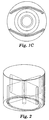
- several patterns are used, including the waffle pattern, peripheral weld pattern, and eyebrow pattern, shown in Figures 1A, 1B, and 1C. In some cases the patterns are used for both cutting and sealing operations.
- a common feature in all patterns is that the internal diameter is greater than 7-10 cm (3-4 in).
- horns used for ultrasonically welding face masks generally have an outside diameter of 15 cm (6 in).
- the horn is formed with multiple slots machined radially through the center, as shown in Figure 2.
- the slots are intended to control the amplitude profile of the horn at the weld surface. Without the slots, the amplitude varies greatly on the weld surface. In some cases, the welding amplitude at certain locations is zero and no welding occurs at these locations.
- This slotted horn is used to perform peripheral welding of face masks and tacking of the layers. Normally a pattern is machined on the end of the horn opposite the input or excitation end. This design is fairly complicated to machine, and has proven to be unreliable in production. This has resulted in significant cost to fabricate spare horns, and in excess machine downtime. Also, the vibration amplitude on the weld surface varies 25-30% along the weld pattern. In order to achieve acceptable welds with this non-uniformity, the dwell time of the welding process must be increased, which results in reduced throughput of the entire machine. Nonuniformity can result in overwelding at some locations, or underwelding at others. This reduces the process window.
- a vibrational horn for imparting energy at a selected wavelength, frequency, and amplitude includes a shaft, a cylinder and a disk portion connecting the shaft and cylinder.
- the shaft receives vibrational energy at an axial input end and transmits the vibrational energy to the disk portion.
- the disk portion transmits the vibrational energy to the cylinder.
- the cylinder has an inner surface, an outer surface, and first and second opposing end surfaces.
- the shaft is located adjacent the first end surface and the second end surface serves as a welding surface which applies vibrational energy to an object.
- the cylinder is hollow and has an outer diameter that is greater than the diameter of the shaft. The welding surface moves as the cylinder expands and contracts with the application of vibrational energy to the input end of the shaft.
- the cylinder can be a right circular cylinder or can have an elliptical diameter or can be rectangular or one of many other shapes.
- the length of the cylinder can be a multiple of approximately one-half wavelength of the horn material.
- the shaft is coaxial with the cylinder.
- the horn can be an ultrasonic horn with the weld surface moving substantially in phase with the movement of the axial input end of the horn.
- the disk portion has a hollow on the side facing away from the welding surface to improve flexing of the cylinder.
- the shaft has a notch formed on the axial output end to minimize stress for a given amplitude of operation.
- the cylinder has an undercut on the inner surface to control the displacement along the welding surface.
- the cylinder has an undercut on the outer surface to obtain the desired amplitude profile along the welding surface.
- the ultrasonic welding horn of this invention can be used to bond multiple layers of material from face masks.
- the horn is designed for plunge welding of a face mask, it can be used to weld other materials such as molded plastic parts, plastic films, and nonwoven materials and to make many other products.
- this horn can be used with other welding processes, such as scan welding, which can be easily accommodated due to the uniformity of the welding surface displacement and the simplicity of the design.
- the horn's size can be scaled up or down with minimal design effort, and any fairly shallow welding pattern can be machined on the welding surface.
- This horn attains more uniform and higher amplitudes, with lower stresses, and can have a larger diameter than known horns. Higher and more uniform amplitudes require less weld time, resulting in a higher machine speed, a wider process window, and the ability to weld thicker and increased numbers of layers. Reduced stress increases the horn reliability and reduces machine down time. The bigger diameter horn accommodates larger weld patterns and provides more options for product enhancements and development.
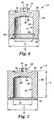
- FIG 4 shows one embodiment of the ultrasonic horn of the invention.
- the horn imparts energy at a selected wavelength, frequency, and amplitude.
- the horn 10 is a hollow cylinder 12 with an inner diameter 14, in the illustrated embodiment, of 10 cm (4 in) and an outer diameter 16 of 16.26 cm (6.4 in).
- This design achieves acceptable uniform amplitude at all points between the inner and outer diameters 14, 16 on the welding face. Therefore, any shallow machined pattern on this welding face should exhibit uniform amplitude. For patterns whose depth is small compared to the length of the horn, extra material can be provided to machine the pattern.
- the total length of the horn is a multiple of approximately one half wavelength of the horn material.
- the horn can be made out of aluminum, titanium, steel or other materials. The horn dimensions depend on the wavelength of the material used to attain the half wavelength length requirement.
- the horn 10 is shown as a single part, conceptually it includes an outer cylinder 12 (having inner and outer diameters 14, 16) and an inner shaft 18 connected by a disk 20.
- the shaft 18 can have any shape.
- a cylindrical shaft is most common.
- the shaft 18 has an axial input end 22 and an axial output end, and receives vibrational energy at the axial input end and transmits the vibrational energy at the axial output end.
- the axial output end is not a defined surface of the shaft 18. It is generally considered to be at the area where the shaft 18 connects to the disk 20.
- the cylinder 12 can be a right circular cylinder, it can have an elliptical diameter, or it can have other shapes, such as polygonal (such as triangular, rectangular, pentagonal, etc.), and combinations of two or more shapes. It could be concave or convex.
- the cylinder 12 is hollow and has an inner surface 26 having the inner diameter 14, an outer surface 28 having the outer diameter 16, and first and second opposing end surfaces 30, 32.
- the shaft 18 is located adjacent the first end surface 30 (connected by the disk 20) and the second end surface 32 serves as a welding surface which applies vibrational energy to an object.
- the welding surface 32 moves as the cylinder 12 expands and contracts with the application of vibrational energy to the input end 22 of the shaft 18.
- the shaft 18 can be coaxial or eccentric with the cylinder 12.
- a tapped hole 24 on the cylinder 12 provides attachment to the booster (not shown) using a threaded stud (not shown).
- both end surfaces 30, 32 can serve as welding surfaces.
- the disk portion 20 connects the inner shaft 18 to the cylinder 12 and transmits the vibrational energy from the inner shaft to the cylinder.
- the disk 20 can be circular although it can be other shapes depending on the shape of the horn.
- the disk portion 20 need not be located adjacent the first end surface 30 of the cylinder 12.
- the disk portion could be located at any axial location with respect to the cylinder 12. Adjusting the location of the disk portion 20 can be used to change the gain of the horn (the ratio of the output to input amplitudes) and the amplitude profile on the weld surface 32. If the disk portion 20 is located centrally, the cylinder 12 can have both end surfaces 30, 32 serve as welding surfaces.
- the disk portion 20 optionally can have an annular hollow portion 34 on the side facing away from the welding surface 32 to improve flexing of the disk 20.
- the shaft 18 optionally can have a notch 36 formed on the axial output end to minimize stress for a given mode of vibration.
- the notch 36 can extend for the entire circumference of the horn or only part.
- the vibration mode is opposite to the conventional horn.
- a half wavelength horn shown in Figure 4, having a length L.
- the input end 22 moves downward
- the welding surface 32 also moves downward, as shown in Figure 5B.
- the displacement of the input end 22 and the welding surface 32 are in the same direction and hence the motion is identified as "in phase.”
- the cylinder 12 acts as a bar horn because the opposing ends 30, 32 are out of phase.
- the outer cylinder 12 goes through compression and tension.
- the cylinder 12 is coupled with the shaft 18 by the disk 20.
- the disk 20 goes through bending motion and experiences radial compressive and tensile stresses.
- the input and output are "in phase.
- the actuating surface a booster mounting surface
- the bottom welding surface moves outward and vice versa.
- the input and output are "out of phase.”
- the actuating surface the input end 22, moves downward, the welding surface 32 moves upward.
- the displacement of the input end 22 and the welding surface 32 are in opposite direction and the motion is "out of phase.”
- horn 10 of the invention is a difference between the horn 10 of the invention and the horn of Figure 2 or Figure 3, is that the entire horn of Figure 2 acts as a half-wavelength bar horn with the input and output surfaces acting axially at all points.
- the outer cylinder 12 acts as a half-wavelength bar horn with the input and output surfaces acting axially.
- the amplitude profile on the welding surface 32, the gain in the horn 10, the resonant frequency, and the stress in the horn are functions of the inner diameter 14, the outer diameter 16, the thickness and axial position of the disk 20, the length of the horn 10, the depth of the hollow 34 and notch 36, and the material used for the horn 10.
- the corners of the cylinder 12 at the first surface 30 can be chamfered.
- the disk portion 20 can extend beyond the outer diameter of the cylinder 12.
- the cylinder 12 can extend beyond the disk portion 20 for all or a portion of the first surface 30.
- FIG. 6 Another design variation of the hollow vibrational horn is shown in Figure 6 which has an outer diameter of 20 cm (8 in) and an inner diameter of 10 cm (4 in).
- an undercut 38 is made on the inner surface 26 of the cylinder 12.
- a similar undercut 40 can be provided on the outer surface 28, if it is required to obtain the desired amplitude profile along the welding surface 32.
- the placement, depth, and width of the undercuts 38, 40 directly influence the amplitude profile on the welding surface 32.
- the undercuts 38, 40 can extend completely around the cylinder 12 or partially around the cylinder.
- a cap 42 can be placed across the second end surface 32 of the cylinder 12, as shown in Figure 7. The cap 42 would serve as a larger welding surface while the horn still operates as a hollow horn as described above.
- a primary advantage of the new hollow horn design, as compared with known horns, is that it has better displacement uniformity or controlled displacement profile. Both measurements and finite element analysis have shown that displacement variation of less than 5% is achieved. Better uniformity means that the dwell time for a plunge welding operation may be reduced, which leads to improved throughput for the welding operation, and often improved throughput for an entire production machine. Better uniformity also gives uniform weld and improved yield with a wider process window.
- the hollow horn of this invention also has lower internal stresses. When internal stresses are reduced, the horn can withstand a greater number of cycles before failure. This leads to less machine downtime and reduced maintenance costs because each horn will last longer. Also, lower internal stresses allow the hom to attain a greater horn amplitude.
- a high amplitude horn can be used for processes that are not feasible with a lower amplitude horn, such as thick layer or multilayer webs for face masks.
- the hollow horn is simple to machine. Simple machining will reduce fabrication costs. This horn should be cheaper to make than the existing horn. Also, the hollow horn has a larger diameter. It can accommodate larger weld patterns, more options for product modifications, and new developments.
- the horn of Figure 4 was made of 7075-T651 aluminum, and its welding frequency was measured to be 20.09 kHz. The gain was approximately 1.2. The output amplitude at the welding surface of the horn was measured when the horn was excited using different boosters as shown below. Booster Ratio Output-Amplitude, Mils p-p 0.67:1 0.41 1.50:1 1.4 2.50:1 2.0 3.75:1 3.5
- the power drawn by the horn in air by the power supply was less than 50 watts, and the horn showed no signs of heating.
- the other vibrational modes of the horn occurred at 18.3 and 21.5 kHz, and are well separated from the operating frequency of 20.09 kHz.
- the uniformity of the amplitude along the weld surface was measured to be within 5%.
- the waffle pattern shown in Figure 1A was applied to another horn with the dimensions as shown in Figure 4, except for the overall length.
- the cylinder length was increased by extending the welding surface downward by 0.25 cm (0.1 in), which is equal to the depth of the pattern.
- the frequency of this horn before machining the pattern was 19.85 kHz. After the waffle pattern was machined, the welding frequency was determined to be 20.01 kHz.
- a horn of Figure 2 with the eyebrow pattern of Figure 1C was made and installed on a production machine. This horn failed frequently and was unreliable. In some cases the horn failed immediately and in some cases after welding 500 parts.
- the hollow horn of this example has welded at least 25,000 parts without failing. Because of the amplitude uniformity there is increased yield in the welding process and a widened process window.
Landscapes
- Engineering & Computer Science (AREA)
- Mechanical Engineering (AREA)
- Physics & Mathematics (AREA)
- Acoustics & Sound (AREA)
- Multimedia (AREA)
- Apparatuses For Generation Of Mechanical Vibrations (AREA)
- Lining Or Joining Of Plastics Or The Like (AREA)
- Pressure Welding/Diffusion-Bonding (AREA)
Applications Claiming Priority (3)
| Application Number | Priority Date | Filing Date | Title |
|---|---|---|---|
| US08/942,469 US5922170A (en) | 1997-10-02 | 1997-10-02 | Hollow vibrational horn |
| US942469 | 1997-10-02 | ||
| PCT/US1998/002029 WO1999017893A1 (en) | 1997-10-02 | 1998-02-05 | Hollow vibrational horn |
Publications (2)
| Publication Number | Publication Date |
|---|---|
| EP1019200A1 EP1019200A1 (en) | 2000-07-19 |
| EP1019200B1 true EP1019200B1 (en) | 2003-05-02 |
Family
ID=25478113
Family Applications (1)
| Application Number | Title | Priority Date | Filing Date |
|---|---|---|---|
| EP98904863A Expired - Lifetime EP1019200B1 (en) | 1997-10-02 | 1998-02-05 | Hollow vibrational horn |
Country Status (10)
| Country | Link |
|---|---|
| US (1) | US5922170A (enExample) |
| EP (1) | EP1019200B1 (enExample) |
| JP (1) | JP4047540B2 (enExample) |
| KR (1) | KR100512656B1 (enExample) |
| AU (1) | AU6264098A (enExample) |
| BR (1) | BR9812596A (enExample) |
| CA (1) | CA2303533C (enExample) |
| DE (1) | DE69814119T2 (enExample) |
| TW (1) | TW429190B (enExample) |
| WO (1) | WO1999017893A1 (enExample) |
Families Citing this family (12)
| Publication number | Priority date | Publication date | Assignee | Title |
|---|---|---|---|---|
| US6059923A (en) * | 1998-09-18 | 2000-05-09 | 3M Innovative Properties Company | Rotary acoustic horn with sleeve |
| FR2809984B1 (fr) * | 2000-06-09 | 2006-07-14 | Aplix Sa | Sonotrode rotative permettant de souder en continu sur une grande largeur |
| FR2817176B1 (fr) * | 2000-11-28 | 2003-02-14 | Forward Technology Ind | Outillage de vibration de grandes dimensions, notamment pour des applications de soudage |
| MXPA05004521A (es) * | 2002-11-01 | 2005-07-26 | Rieke Corp | Pico soldador. |
| US7992566B2 (en) * | 2002-12-30 | 2011-08-09 | Quiescence Medical, Inc. | Apparatus and methods for treating sleep apnea |
| US8146600B2 (en) * | 2003-07-22 | 2012-04-03 | Quiescence Medical, Inc. | Apparatus and methods for treating sleep apnea |
| DE102011005536A1 (de) * | 2011-03-15 | 2012-09-20 | Herrmann Ultraschalltechnik Gmbh & Co. Kg | Sonotrode mit Bearbeitungskanal |
| DE102012216584A1 (de) * | 2012-09-17 | 2014-03-20 | Ms Spaichingen Gmbh | Sonotrodenhalterung |
| DE102013202766A1 (de) * | 2013-02-20 | 2014-08-21 | Ms Spaichingen Gmbh | Rundsonotrode |
| CN106457459B (zh) * | 2014-06-09 | 2019-05-28 | 必能信超声公司 | 高带宽大表面积的块状超声波焊头 |
| ITUA20163828A1 (it) * | 2016-05-26 | 2017-11-26 | Gd Spa | Sonotrodo per la saldatura ad ultrasuoni di componenti plastici di una sigaretta elettronica |
| US10265913B2 (en) | 2016-11-23 | 2019-04-23 | GM Global Technology Operations LLC | Horn for an ultrasonic welding process |
Family Cites Families (10)
| Publication number | Priority date | Publication date | Assignee | Title |
|---|---|---|---|---|
| DE1227702B (de) * | 1961-08-17 | 1966-10-27 | Jenoptik Jena Gmbh | Ultraschall-Amplituden-Transformator |
| DE2338908C3 (de) * | 1973-08-01 | 1981-06-04 | Elbatainer Kunststoff- Und Verpackungsgesellschaft Mbh, 7505 Ettlingen | Ultraschall-Schweißverfahren und -vorrichtung zum flüssigkeitsdichten Einschweißen eines verschließbaren Gießstutzens in einen dünnwandigen Flüssigkeitsbehälter sowie ein Gießstutzen hierfür |
| DE2542969C2 (de) * | 1975-09-26 | 1984-07-12 | Elbatainer Kunststoff- Und Verpackungsgesellschaft Mbh, 7505 Ettlingen | Vorrichtung zum flüssigkeitsdichten Einschweißen eines verschließbaren Gießstutzens mittels Ultraschall |
| US4131505A (en) * | 1977-12-12 | 1978-12-26 | Dukane Corporation | Ultra-sonic horn |
| JPS62273832A (ja) * | 1986-05-23 | 1987-11-27 | Eiji Mori | 超音波プラスチツクウエルダ−用工具ホ−ン |
| CH671529A5 (en) * | 1987-03-06 | 1989-09-15 | Hansen Dieter Ag | Ultrasound processing tool with vibration mass - has separate spring properties from mass for vibration across transformer axis |
| US5244520A (en) * | 1990-07-12 | 1993-09-14 | International Paper Company | Pour spout construction and method |
| US5275767A (en) * | 1991-06-19 | 1994-01-04 | Micciche Frank S | Manufacture of plastic containers |
| DE4313875C3 (de) * | 1993-04-28 | 2001-01-18 | Karl Widmann Schweismaschinen | Vorrichtung zum Herstellen von Einsteckhüllen oder Einbanddecken |
| US5421923A (en) * | 1993-12-03 | 1995-06-06 | Baxter International, Inc. | Ultrasonic welding horn with sonics dampening insert |
-
1997
- 1997-10-02 US US08/942,469 patent/US5922170A/en not_active Expired - Lifetime
-
1998
- 1998-02-05 BR BR9812596-6A patent/BR9812596A/pt not_active IP Right Cessation
- 1998-02-05 CA CA002303533A patent/CA2303533C/en not_active Expired - Fee Related
- 1998-02-05 DE DE69814119T patent/DE69814119T2/de not_active Expired - Lifetime
- 1998-02-05 KR KR10-2000-7003525A patent/KR100512656B1/ko not_active Expired - Lifetime
- 1998-02-05 WO PCT/US1998/002029 patent/WO1999017893A1/en not_active Ceased
- 1998-02-05 EP EP98904863A patent/EP1019200B1/en not_active Expired - Lifetime
- 1998-02-05 AU AU62640/98A patent/AU6264098A/en not_active Abandoned
- 1998-02-05 JP JP2000514750A patent/JP4047540B2/ja not_active Expired - Fee Related
- 1998-09-16 TW TW087115432A patent/TW429190B/zh not_active IP Right Cessation
Also Published As
| Publication number | Publication date |
|---|---|
| JP4047540B2 (ja) | 2008-02-13 |
| CA2303533A1 (en) | 1999-04-15 |
| TW429190B (en) | 2001-04-11 |
| WO1999017893A1 (en) | 1999-04-15 |
| CA2303533C (en) | 2004-01-06 |
| AU6264098A (en) | 1999-04-27 |
| KR100512656B1 (ko) | 2005-09-07 |
| JP2001519225A (ja) | 2001-10-23 |
| KR20010024383A (ko) | 2001-03-26 |
| DE69814119T2 (de) | 2003-10-23 |
| US5922170A (en) | 1999-07-13 |
| EP1019200A1 (en) | 2000-07-19 |
| DE69814119D1 (en) | 2003-06-05 |
| BR9812596A (pt) | 2000-08-01 |
Similar Documents
| Publication | Publication Date | Title |
|---|---|---|
| EP1019200B1 (en) | Hollow vibrational horn | |
| US5707483A (en) | Rotary acoustic horn | |
| US5645681A (en) | Stacked rotary acoustic horn | |
| CN100374284C (zh) | 对称超声波旋转焊头 | |
| KR100939386B1 (ko) | 진동 요소용 마운트 | |
| US5976316A (en) | Non-nodal mounting system for acoustic horn | |
| US7718022B2 (en) | Resonant nodal mount for linear ultrasonic horns | |
| US7754141B2 (en) | Bi-material ultrasonic horn with integral isolation member | |
| EP1633497B1 (en) | Ultrasonic horn mount | |
| US20030107299A1 (en) | Vibration wave driving apparatus, and method of setting shape of support member supporting elastic member forming vibration member of vibration wave driving apparatus | |
| EP3838562B1 (en) | Servo-driven ultrasonic welding system and method for welding to a thin part without read-through | |
| EP1866104B1 (en) | Rotary ultrasonic sealer | |
| US20020134813A1 (en) | Large vibration tool, especially for welding applications | |
| MXPA00003148A (en) | Hollow vibrational horn | |
| US20230038455A1 (en) | Rotary Acoustic Horn | |
| JPH03198673A (ja) | 超音波モータ | |
| JP2002524254A (ja) | 超音波ホーン |
Legal Events
| Date | Code | Title | Description |
|---|---|---|---|
| PUAI | Public reference made under article 153(3) epc to a published international application that has entered the european phase |
Free format text: ORIGINAL CODE: 0009012 |
|
| 17P | Request for examination filed |
Effective date: 20000428 |
|
| AK | Designated contracting states |
Kind code of ref document: A1 Designated state(s): CH DE FR GB IT LI NL |
|
| 17Q | First examination report despatched |
Effective date: 20010108 |
|
| GRAG | Despatch of communication of intention to grant |
Free format text: ORIGINAL CODE: EPIDOS AGRA |
|
| GRAG | Despatch of communication of intention to grant |
Free format text: ORIGINAL CODE: EPIDOS AGRA |
|
| GRAG | Despatch of communication of intention to grant |
Free format text: ORIGINAL CODE: EPIDOS AGRA |
|
| GRAH | Despatch of communication of intention to grant a patent |
Free format text: ORIGINAL CODE: EPIDOS IGRA |
|
| GRAH | Despatch of communication of intention to grant a patent |
Free format text: ORIGINAL CODE: EPIDOS IGRA |
|
| GRAH | Despatch of communication of intention to grant a patent |
Free format text: ORIGINAL CODE: EPIDOS IGRA |
|
| GRAH | Despatch of communication of intention to grant a patent |
Free format text: ORIGINAL CODE: EPIDOS IGRA |
|
| GRAA | (expected) grant |
Free format text: ORIGINAL CODE: 0009210 |
|
| AK | Designated contracting states |
Designated state(s): CH DE FR GB IT LI NL |
|
| REG | Reference to a national code |
Ref country code: GB Ref legal event code: FG4D |
|
| REG | Reference to a national code |
Ref country code: CH Ref legal event code: EP |
|
| REG | Reference to a national code |
Ref country code: CH Ref legal event code: NV Representative=s name: E. BLUM & CO. PATENTANWAELTE |
|
| REF | Corresponds to: |
Ref document number: 69814119 Country of ref document: DE Date of ref document: 20030605 Kind code of ref document: P |
|
| ET | Fr: translation filed | ||
| PLBE | No opposition filed within time limit |
Free format text: ORIGINAL CODE: 0009261 |
|
| STAA | Information on the status of an ep patent application or granted ep patent |
Free format text: STATUS: NO OPPOSITION FILED WITHIN TIME LIMIT |
|
| 26N | No opposition filed |
Effective date: 20040203 |
|
| PGFP | Annual fee paid to national office [announced via postgrant information from national office to epo] |
Ref country code: NL Payment date: 20060116 Year of fee payment: 9 |
|
| REG | Reference to a national code |
Ref country code: CH Ref legal event code: PFA Owner name: MINNESOTA MINING AND MANUFACTURING COMPANY Free format text: MINNESOTA MINING AND MANUFACTURING COMPANY#3M CENTER, P.O. BOX 33427#ST. PAUL, MINNESOTA 55133-3427 (US) -TRANSFER TO- MINNESOTA MINING AND MANUFACTURING COMPANY#3M CENTER, P.O. BOX 33427#ST. PAUL, MINNESOTA 55133-3427 (US) |
|
| NLV4 | Nl: lapsed or anulled due to non-payment of the annual fee |
Effective date: 20070901 |
|
| PG25 | Lapsed in a contracting state [announced via postgrant information from national office to epo] |
Ref country code: NL Free format text: LAPSE BECAUSE OF NON-PAYMENT OF DUE FEES Effective date: 20070901 |
|
| PGFP | Annual fee paid to national office [announced via postgrant information from national office to epo] |
Ref country code: FR Payment date: 20070221 Year of fee payment: 10 |
|
| PGFP | Annual fee paid to national office [announced via postgrant information from national office to epo] |
Ref country code: GB Payment date: 20080227 Year of fee payment: 11 |
|
| REG | Reference to a national code |
Ref country code: FR Ref legal event code: ST Effective date: 20081031 |
|
| PG25 | Lapsed in a contracting state [announced via postgrant information from national office to epo] |
Ref country code: FR Free format text: LAPSE BECAUSE OF NON-PAYMENT OF DUE FEES Effective date: 20080229 |
|
| GBPC | Gb: european patent ceased through non-payment of renewal fee |
Effective date: 20090205 |
|
| PG25 | Lapsed in a contracting state [announced via postgrant information from national office to epo] |
Ref country code: GB Free format text: LAPSE BECAUSE OF NON-PAYMENT OF DUE FEES Effective date: 20090205 |
|
| PGFP | Annual fee paid to national office [announced via postgrant information from national office to epo] |
Ref country code: CH Payment date: 20100224 Year of fee payment: 13 |
|
| PGFP | Annual fee paid to national office [announced via postgrant information from national office to epo] |
Ref country code: IT Payment date: 20100224 Year of fee payment: 13 |
|
| REG | Reference to a national code |
Ref country code: CH Ref legal event code: PL |
|
| PG25 | Lapsed in a contracting state [announced via postgrant information from national office to epo] |
Ref country code: CH Free format text: LAPSE BECAUSE OF NON-PAYMENT OF DUE FEES Effective date: 20110228 Ref country code: LI Free format text: LAPSE BECAUSE OF NON-PAYMENT OF DUE FEES Effective date: 20110228 |
|
| PG25 | Lapsed in a contracting state [announced via postgrant information from national office to epo] |
Ref country code: IT Free format text: LAPSE BECAUSE OF NON-PAYMENT OF DUE FEES Effective date: 20110205 |
|
| PGFP | Annual fee paid to national office [announced via postgrant information from national office to epo] |
Ref country code: DE Payment date: 20170131 Year of fee payment: 20 |
|
| REG | Reference to a national code |
Ref country code: DE Ref legal event code: R071 Ref document number: 69814119 Country of ref document: DE |