EP1018656B1 - Fibre optique à faible pente de dispersion chromatique - Google Patents
Fibre optique à faible pente de dispersion chromatique Download PDFInfo
- Publication number
- EP1018656B1 EP1018656B1 EP99403160A EP99403160A EP1018656B1 EP 1018656 B1 EP1018656 B1 EP 1018656B1 EP 99403160 A EP99403160 A EP 99403160A EP 99403160 A EP99403160 A EP 99403160A EP 1018656 B1 EP1018656 B1 EP 1018656B1
- Authority
- EP
- European Patent Office
- Prior art keywords
- chromatic dispersion
- index
- fibre according
- maximum
- wavelength
- Prior art date
- Legal status (The legal status is an assumption and is not a legal conclusion. Google has not performed a legal analysis and makes no representation as to the accuracy of the status listed.)
- Expired - Lifetime
Links
Images
Classifications
-
- G—PHYSICS
- G02—OPTICS
- G02B—OPTICAL ELEMENTS, SYSTEMS OR APPARATUS
- G02B6/00—Light guides; Structural details of arrangements comprising light guides and other optical elements, e.g. couplings
- G02B6/02—Optical fibres with cladding with or without a coating
- G02B6/02214—Optical fibres with cladding with or without a coating tailored to obtain the desired dispersion, e.g. dispersion shifted, dispersion flattened
- G02B6/02219—Characterised by the wavelength dispersion properties in the silica low loss window around 1550 nm, i.e. S, C, L and U bands from 1460-1675 nm
- G02B6/02228—Dispersion flattened fibres, i.e. having a low dispersion variation over an extended wavelength range
- G02B6/02238—Low dispersion slope fibres
- G02B6/02242—Low dispersion slope fibres having a dispersion slope <0.06 ps/km/nm2
-
- G—PHYSICS
- G02—OPTICS
- G02B—OPTICAL ELEMENTS, SYSTEMS OR APPARATUS
- G02B6/00—Light guides; Structural details of arrangements comprising light guides and other optical elements, e.g. couplings
- G02B6/02—Optical fibres with cladding with or without a coating
- G02B6/036—Optical fibres with cladding with or without a coating core or cladding comprising multiple layers
- G02B6/03616—Optical fibres characterised both by the number of different refractive index layers around the central core segment, i.e. around the innermost high index core layer, and their relative refractive index difference
- G02B6/03638—Optical fibres characterised both by the number of different refractive index layers around the central core segment, i.e. around the innermost high index core layer, and their relative refractive index difference having 3 layers only
- G02B6/03644—Optical fibres characterised both by the number of different refractive index layers around the central core segment, i.e. around the innermost high index core layer, and their relative refractive index difference having 3 layers only arranged - + -
-
- G—PHYSICS
- G02—OPTICS
- G02B—OPTICAL ELEMENTS, SYSTEMS OR APPARATUS
- G02B6/00—Light guides; Structural details of arrangements comprising light guides and other optical elements, e.g. couplings
- G02B6/02—Optical fibres with cladding with or without a coating
- G02B6/036—Optical fibres with cladding with or without a coating core or cladding comprising multiple layers
- G02B6/03616—Optical fibres characterised both by the number of different refractive index layers around the central core segment, i.e. around the innermost high index core layer, and their relative refractive index difference
- G02B6/03661—Optical fibres characterised both by the number of different refractive index layers around the central core segment, i.e. around the innermost high index core layer, and their relative refractive index difference having 4 layers only
- G02B6/03666—Optical fibres characterised both by the number of different refractive index layers around the central core segment, i.e. around the innermost high index core layer, and their relative refractive index difference having 4 layers only arranged - + - +
Definitions
- the present invention relates to the field of optical fiber transmissions, and more particularly to the field of wavelength division multiplex transmissions.
- the refractive index profile is generally qualified as a function of the shape of the graph of the function which the radius associates with the refractive index.
- the distance r at the center of the fiber is conventionally represented on the abscissae, and the index is defined by its absolute difference or in percent with respect to the index of the cladding of the fiber.
- This is referred to as a "step”, “trapezium” or “triangle” index profile for curves representative of the variation of the index as a function of the radius, which have respective shapes of step, trapezoid or triangle.
- the objective is to obtain, for all wavelength values of the multiplex, a cumulative chromatic dispersion substantially zero on the link, so as to limit the expansion of the pulses.
- a cumulative value of a few hundred ps / nm for dispersion is acceptable. It is also interesting to avoid near the wavelengths used in the system the null values of the chromatic dispersion, for which the nonlinear effects are more important.
- fibers called NZ-DSF non-zero DSF
- ⁇ 0 of zero chromatic dispersion outside the channel range of the multiplex are preferably used to avoid problems caused by the four-wave mixture.
- the use of these fibers for wavelength division multiplex systems leads to the search for a low chromatic dispersion slope, so as to maintain similar propagation characteristics for the different channels. From this point of view, the reference value for the chromatic dispersion slope is 0.075 ps / nm 2 .km.
- the fibers obtained have a core of index greater than that of the outer sheath, a first sheath of index less than that of the outer sheath, and a second cladding of index greater than that of the outer sheath.
- the losses induced by a winding of the fiber over a radius of 5 cm are less than 2.4 dB / km, and the dispersion is less than 3 ps / nm.km in the wavelength range between 1300 and 1550 nm. .
- EP-A-0 368 014 describes another fiber having the same type of profile. It has between 1280 and 1560 nm a chromatic dispersion less than or equal to 3.5 ps / nm.km, and a sensitivity to the curvature less than 10 -6 dB / m for a radius of 5 cm.
- EP-A-0 131 634 still describes a fiber having the same type of profile. This fiber has a chromatic dispersion with three dispersion zeros, and opposite values of the relative maxima and minima of the dispersion between the zeros.
- PK Bachmann Worldwide status of dispersion-modified single mode fibers, Philips J. Res.42, 435-450, (1987) proposes a review of flat dispersion and shifted dispersion (DSF) fibers. The author concludes on the need to reduce the losses induced by curvature of the fibers.
- LG Cohen et al. Electronic Letters, vol.18, 1982, p.1023-1024 discloses a dispersion-shifted single-mode fiber having an index profile with a core having an index greater than the index of the outer cladding, followed by a buried annular portion of index less than that of the outer sheath, followed by a ring of index greater than that of the outer sheath, followed by a buried annular portion of index lower than that of the outer sheath.
- the invention proposes a fiber which has characteristics suitable for use in wavelength division multiplex transmission systems, without inducing significant attenuation, and limiting the non-linear effects.
- the invention applies to multiplex pulse wavelength multiplex transmission systems of any kind, and in particular to RZ or NRZ pulses.
- the invention provides a dispersion mode single mode optical fiber as defined in claim 1.
- the maximum is unique in the wavelength range of 1400 to 1650 nm.
- the fiber has a positive chromatic dispersion value at said maximum.
- the maximum is advantageously achieved for a wavelength between 1530 and 1580 nm.
- the fiber may have a chromatic dispersion zero for a wavelength of less than 1450 nm.
- the fiber has a negative chromatic dispersion value at said maximum.
- the maximum is preferably reached for a wavelength between 1480 and 1520 nm.
- the fiber may further have in the wavelength range of 1530 to 1580 a positive chromatic dispersion slope.
- the fiber has a negative chromatic dispersion slope in the wavelength range of 1530 to 1580.
- the fiber has in the wavelength range of 1530 to 1580 a lower chromatic dispersion slope in absolute value at 0.03 ps / nm 2 .km.
- the fiber exhibits for a wavelength of 1300 nm a lower chromatic dispersion in absolute value at 7 ps / nm.km.
- the fiber has an index profile with a fiber core and a sheath, the core comprising a central portion of index (n 1 ) greater than that (n s ) of the sheath of the fiber, an annular portion of index (n 2 ) less than that of the sheath around said central portion, and a ring index (n 3 ) greater than that of the sheath around said annular portion.
- the difference of the indices of the central portion and the annular portion is between 13.10 -3 and 17.10 -3 .
- the difference ( ⁇ n 2 ) between the index (n 2 ) of the annular part and the index (n s ) of the sheath is between -8.10 -3 and -6.10 -3 .
- the difference ( ⁇ n 3 ) between the index (n 3 ) of the ring and the index (n s ) of the cladding is between 3.10 -3 and 6.10 -3 .
- the radius (a 1 ) of the central portion is less than or equal to 3 microns.
- the ratio (a 2 - a 1 ) / a 1 between the thickness of the annular portion and the radius of the central portion is between 0.8 and 1.2.
- the ratio (a 3 - a 2 ) / a 1 between the thickness of the ring and the radius of the central portion is between 0.3 and 0.7.
- the invention further proposes the use of such a fiber for wavelength division multiplex transmission systems.
- the invention provides a dispersion-shifted single-mode optical fiber having, in a wavelength range of 1400 to 1650 nm, a maximum of the chromatic dispersion, and a chromatic dispersion slope in absolute value of less than 0.05. ps / nm 2 .km.
- the maximum of the chromatic dispersion is unique in this range of wavelengths.
- Chromatic dispersion may have a positive or negative value for this maximum. If the chromatic dispersion has a maximum positive value, the fiber may have a chromatic dispersion zero on either side of the maximum. The position of the maximum of the dispersion is then preferably selected from the wavelength range of the multiplex, or between 1530 and 1580 nm.
- the chromatic dispersion is canceled a first time for a wavelength value of less than 1450 nm. It can cancel itself a second time for a wavelength value greater than 1600 nm.
- the fiber is NZ-DSF, ie does not exhibit dispersion zeros in the wavelength range of the comb, between 1530 and 1580 nm, and is particularly suitable for use with multiplex transmission systems. in wavelength.
- the non-zero values of the dispersion make it possible to limit the nonlinear effects, for example the four-wave mixing.
- the position of this maximum is advantageously chosen so that in the wavelength range of the multiplex, the chromatic dispersion and the chromatic dispersion slope are negative.
- a maximum of chromatic dispersion is chosen between 1480 and 1520 nm, preferably close to 1500 nm, a negative chromatic dispersion and a negative dispersion slope can be obtained in the multiplex range.
- the advantage in this case is that it is possible in the transmission system to use, for the compensation of the dispersion, an index jump fiber with a positive dispersion slope, and a positive dispersion. It is then not necessary to use a highly attenuating dispersion compensating fiber having a small mode diameter; such chromatic dispersion management is described in the patent application filed by the applicant on the same day as the present application, under the title “Fiber optic transmission system. wavelength division multiplexing. "It is proposed to use as low-slope fiber line fiber, with chromatic dispersion in absolute value between 3 and 5.5 ps / nm.km in a range of lengths. from 1530 to 1600 nm, and a lower chromatic dispersion slope in absolute value at 0.04 ps / nm 2 .km in a wavelength range of 1530 to 1600 nm.
- Negative chromatic dispersion and positive chromatic dispersion slope could also be selected in the multiplex wavelength range, or positive chromatic dispersion and negative chromatic dispersion slope in the wavelength range of the multiplex.
- the low values of the dispersion slope ensure that the channels of the multiplex are transmitted without significant differences in the transmission characteristics.
- these values of the dispersion slope ensure that the fiber of the invention also has low dispersion values around 1300 nm, and can thus also be used around this wavelength value.
- the fiber of the invention also has in the multiplex range a lower chromatic dispersion slope in absolute value at 0.03 ps / nm 2 .km.
- a lower chromatic dispersion slope in absolute value at 0.03 ps / nm 2 .km Such a value has the advantage of limiting the distortions between the different channels of the comb.
- the fiber preferably has a low chromatic dispersion at 1300 nm, and typically a lower chromatic dispersion in absolute value at 7 ps / nm.km.
- FIG. 1 shows an exemplary index profile of a fiber according to the invention.
- the index profile of FIG. 1 is a ringed rectangle index profile. This profile has, starting from the center of the fiber towards the sheath, a central portion of index n 1 substantially constant, up to a radius a 1 .
- the index n 1 is greater than the index n s silica of the sheath.
- the difference ⁇ n 1 between the index n 1 and the index of the cladding is 10 ⁇ 10 -3
- the radius a 1 is 2.7 ⁇ m.
- the fiber of the invention has a buried annular portion, of index n 2 less than that of the sheath, between the ⁇ 1 and ⁇ 2 rays.
- the difference ⁇ n 2 between the index n 2 and index of the cladding is -6.10 -3
- the buried portion extends over a thickness of 2.7 ⁇ m.
- the fiber has around the buried part a ring of index n 3 , greater than that of the sheath, between spokes a 2 and a 3 .
- the difference ⁇ n 3 between the index n 3 of the ring and the index of the sheath is 3.2 ⁇ 10 -3
- the ring has a thickness of 1.35 ⁇ m. so that the radius at 3 is 6.75 ⁇ m.
- This choice of index profile ensures that the slope of the chromatic dispersion remains less than 0.05 ps / nm 2 .km between 1300 and 1600 nm. More precisely, the chromatic dispersion in this example has a maximum value of -0.6 ps / nm.km for a wavelength value of 1500 nm.
- the fiber of Figure 1 presents the following values of chromatic dispersion, in ps / nm.km: 1450 nm 1500 nm 1550 nm 1600 nm -0.7 -0.6 -0.95 -1.8
- the maximum of the chromatic dispersion is reached for a negative value of the dispersion, and the chromatic dispersion is negative in the wavelength range of the multiplex.
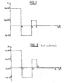
- FIG. 2 shows an example of an index profile according to the prior art.
- the index profile is a ring-shaped rectangle profile, as in FIG. 1, but with a part buried around the ring.
- This profile has, starting from the center of the fiber towards the sheath, a central portion of index n 1 substantially constant, up to a radius a 1 .
- the index n 1 is greater than the index n s of the silica of the cladding.
- the difference ⁇ n 1 between the index n 1 and the index of the sheath is 10 ⁇ 10 -3 .
- the fiber of FIG. 2 has a buried annular portion, of index n 2 less than that of the sheath, between the spokes a 1 and a 2 .
- the difference ⁇ n 2 between the index n 2 and the index of the sheath is -6.10 -3 .
- the fiber has around the buried part a ring of index n 3 , greater than that of the sheath, between spokes a 2 and a 3 .
- the difference ⁇ n 3 between the index n 3 of the ring and the index of the sheath is 5.10 -3 .
- the fiber still has a buried part between radii 3 and 4 , of index n 4 lower than the index of the cladding, and greater than the index of the buried part extending between the rectangle and the ring.
- the difference ⁇ n 4 between the index n 3 of the ring and the index of the cladding is -0.3.10 -3 .
- positive dispersion values are found in the range of 1450 to 1650 nm, and a maximum of the dispersion in this range.
- the maximum is reached around 1500 nm, and the dispersion values are positive, then negative.
- the maximum is reached around 1550 nm, and the dispersion values are positive in the comb range.
- the maximum is reached around 1550 nm in the first case and around 1600 nm in the second case.
- the invention can be obtained by a combination of the following characteristics: 13.10 - 3 ⁇ .DELTA.N 1 - .DELTA.N 2 ⁇ 17.10 - 3 - 8.10 - 3 ⁇ .DELTA.N 2 ⁇ - 6.10 - 3 3.10 - 3 ⁇ .DELTA.N 3 ⁇ 6.10 - 3 at 1 ⁇ 3 microns 0 , 8 ⁇ at 2 - at 1 / at 1 ⁇ 1 , 2 0 , 3 ⁇ at 3 - at 2 / at 1 ⁇ 0 , 7
- the invention may be manufactured by those skilled in the art using known techniques, such as MCVD or other techniques commonly used for the manufacture of optical fibers.
Landscapes
- Physics & Mathematics (AREA)
- Chemical & Material Sciences (AREA)
- Dispersion Chemistry (AREA)
- General Physics & Mathematics (AREA)
- Optics & Photonics (AREA)
- Optical Communication System (AREA)
- Optical Fibers, Optical Fiber Cores, And Optical Fiber Bundles (AREA)
- Glass Compositions (AREA)
Applications Claiming Priority (2)
| Application Number | Priority Date | Filing Date | Title |
|---|---|---|---|
| FR9900007A FR2788138B1 (fr) | 1999-01-04 | 1999-01-04 | Fibre optique a faible pente de dispersion chromatique |
| FR9900007 | 1999-01-04 |
Publications (2)
| Publication Number | Publication Date |
|---|---|
| EP1018656A1 EP1018656A1 (fr) | 2000-07-12 |
| EP1018656B1 true EP1018656B1 (fr) | 2008-01-23 |
Family
ID=9540612
Family Applications (1)
| Application Number | Title | Priority Date | Filing Date |
|---|---|---|---|
| EP99403160A Expired - Lifetime EP1018656B1 (fr) | 1999-01-04 | 1999-12-16 | Fibre optique à faible pente de dispersion chromatique |
Country Status (9)
| Country | Link |
|---|---|
| US (1) | US6535675B1 (ja) |
| EP (1) | EP1018656B1 (ja) |
| JP (2) | JP4434398B2 (ja) |
| CN (1) | CN1163768C (ja) |
| AT (1) | ATE384966T1 (ja) |
| BR (1) | BR9905987A (ja) |
| DE (1) | DE69938033T2 (ja) |
| DK (1) | DK1018656T3 (ja) |
| FR (1) | FR2788138B1 (ja) |
Families Citing this family (11)
| Publication number | Priority date | Publication date | Assignee | Title |
|---|---|---|---|---|
| KR100636332B1 (ko) * | 1998-09-21 | 2006-10-19 | 피렐리 카비 에 시스테미 소시에떼 퍼 아찌오니 | 확장 파장 밴드용의 광파이버 |
| FR2815420B1 (fr) * | 2000-10-16 | 2003-05-16 | Cit Alcatel | Compensation de la dispersion chromatique dans un systeme de transmission a fibre optique, et fibre de compensation |
| JP2002148464A (ja) * | 2000-11-07 | 2002-05-22 | Furukawa Electric Co Ltd:The | 光ファイバ |
| JP4443788B2 (ja) * | 2001-03-30 | 2010-03-31 | 古河電気工業株式会社 | 光ファイバおよびその光ファイバを用いた光通信システム |
| FR2828742B1 (fr) * | 2001-08-16 | 2004-01-16 | Cit Alcatel | Fibre a changement continu de dispersion chromatique |
| FR2828939B1 (fr) | 2001-08-27 | 2004-01-16 | Cit Alcatel | Fibre optique pour un systeme de transmission a multiplexage en longueurs d'onde |
| US20040052486A1 (en) * | 2002-09-13 | 2004-03-18 | Fitel Usa Corp. | Optical fibers and modules for dispersion compensation with simultaneous raman amplification |
| FR2849213B1 (fr) * | 2002-12-24 | 2005-03-04 | Cit Alcatel | Fibre optique |
| US7103251B2 (en) * | 2002-12-31 | 2006-09-05 | Corning Incorporated | Dispersion flattened NZDSF fiber |
| US7437045B2 (en) * | 2006-05-02 | 2008-10-14 | Sterlite Technologies Limited | Dispersion optimized optical fiber for wideband optical transmission |
| CN103149630B (zh) * | 2013-03-06 | 2016-02-24 | 长飞光纤光缆股份有限公司 | 一种低衰减单模光纤 |
Citations (2)
| Publication number | Priority date | Publication date | Assignee | Title |
|---|---|---|---|---|
| US4372647A (en) * | 1979-10-08 | 1983-02-08 | Nippon Telegraph & Telephone Public Corporation | Single mode optical fibers |
| US4435040A (en) * | 1981-09-03 | 1984-03-06 | Bell Telephone Laboratories, Incorporated | Double-clad optical fiberguide |
Family Cites Families (12)
| Publication number | Priority date | Publication date | Assignee | Title |
|---|---|---|---|---|
| JPS583206B2 (ja) * | 1979-10-08 | 1983-01-20 | 日本電信電話株式会社 | 中間層付単一モ−ド光フアイバ |
| JPS6023321B2 (ja) * | 1980-07-14 | 1985-06-07 | 日本電信電話株式会社 | 屈折率溝付形単一モ−ド光フアイバ |
| DE3376884D1 (de) * | 1983-06-29 | 1988-07-07 | Ant Nachrichtentech | Single-mode w-fibre |
| DE3837792A1 (de) * | 1988-11-08 | 1990-05-10 | Kabelmetal Electro Gmbh | Monomodefaser aus quarzglas |
| JPH08136758A (ja) * | 1994-09-13 | 1996-05-31 | Furukawa Electric Co Ltd:The | 波長多重伝送用分散補償光ファイバ |
| CA2157828C (en) * | 1994-09-13 | 2003-02-11 | Youichi Akasaka | Dispersion compensating optical fiber for wavelength division multiplex transmission |
| CA2170815C (en) * | 1995-03-10 | 2002-05-28 | Youichi Akasaka | Dispersion compensating optical fiber |
| JP2988571B2 (ja) * | 1995-03-10 | 1999-12-13 | 古河電気工業株式会社 | 分散補償光ファイバ |
| US5684909A (en) * | 1996-02-23 | 1997-11-04 | Corning Inc | Large effective area single mode optical waveguide |
| CA2202586C (en) * | 1996-04-15 | 2003-05-06 | Masashi Onishi | Dispersion compensating fiber and optical transmission system including the same |
| JP3760557B2 (ja) * | 1996-04-15 | 2006-03-29 | 住友電気工業株式会社 | 分散補償ファイバ及びそれを含む光伝送システム |
| US5878182A (en) * | 1997-06-05 | 1999-03-02 | Lucent Technologies Inc. | Optical fiber having a low-dispersion slope in the erbium amplifier region |
-
1999
- 1999-01-04 FR FR9900007A patent/FR2788138B1/fr not_active Expired - Fee Related
- 1999-12-16 DE DE69938033T patent/DE69938033T2/de not_active Expired - Lifetime
- 1999-12-16 DK DK99403160T patent/DK1018656T3/da active
- 1999-12-16 EP EP99403160A patent/EP1018656B1/fr not_active Expired - Lifetime
- 1999-12-16 AT AT99403160T patent/ATE384966T1/de not_active IP Right Cessation
- 1999-12-23 US US09/471,688 patent/US6535675B1/en not_active Expired - Fee Related
- 1999-12-27 BR BR9905987-8A patent/BR9905987A/pt not_active Application Discontinuation
- 1999-12-28 JP JP37446199A patent/JP4434398B2/ja not_active Expired - Fee Related
- 1999-12-30 CN CNB991274490A patent/CN1163768C/zh not_active Expired - Fee Related
-
2009
- 2009-11-24 JP JP2009265919A patent/JP4527192B2/ja not_active Expired - Fee Related
Patent Citations (2)
| Publication number | Priority date | Publication date | Assignee | Title |
|---|---|---|---|---|
| US4372647A (en) * | 1979-10-08 | 1983-02-08 | Nippon Telegraph & Telephone Public Corporation | Single mode optical fibers |
| US4435040A (en) * | 1981-09-03 | 1984-03-06 | Bell Telephone Laboratories, Incorporated | Double-clad optical fiberguide |
Non-Patent Citations (1)
| Title |
|---|
| L.G.COHEN ET AL., ELECTRONICS LETTERS, vol. 18, no. 24, 25 November 1982 (1982-11-25), Stevenage, Herts, GB, pages 1023 - 1024 * |
Also Published As
| Publication number | Publication date |
|---|---|
| CN1163768C (zh) | 2004-08-25 |
| CN1261676A (zh) | 2000-08-02 |
| EP1018656A1 (fr) | 2000-07-12 |
| JP4527192B2 (ja) | 2010-08-18 |
| JP2000206355A (ja) | 2000-07-28 |
| US6535675B1 (en) | 2003-03-18 |
| JP2010044426A (ja) | 2010-02-25 |
| DK1018656T3 (da) | 2008-03-03 |
| FR2788138A1 (fr) | 2000-07-07 |
| DE69938033T2 (de) | 2009-01-15 |
| BR9905987A (pt) | 2000-10-24 |
| JP4434398B2 (ja) | 2010-03-17 |
| ATE384966T1 (de) | 2008-02-15 |
| DE69938033D1 (de) | 2008-03-13 |
| FR2788138B1 (fr) | 2001-03-30 |
Similar Documents
| Publication | Publication Date | Title |
|---|---|---|
| EP1030199B1 (fr) | Fibre de ligne pour systèmes de transmission à fibre optique à multiplexage en longueurs d'onde | |
| EP1067412B1 (fr) | Fibre optique à compensation de dispersion chromatique | |
| JP4527192B2 (ja) | 波長分散勾配が小さい光ファイバ | |
| FR2782391A1 (fr) | Ajout d'un anneau externe au profil d'indice d'une fibre optique monomode a dispersion decalee | |
| EP1081514B1 (fr) | Fibre optique pour la compensation de la dispersion chromatique d'une fibre optique à dispersion chromatique positive | |
| EP0987569B1 (fr) | Fibre optique monomode à dispersion décalée optimisée pour les hauts débits | |
| EP1217399B1 (fr) | Fibre pour la compensation de dispersion chromatique d'une fibre NZ-DSF à dispersion chromatique positive | |
| FR2784197A1 (fr) | Fibre optique monomode a dispersion decalee a grande aire effective | |
| EP1128196B1 (fr) | Fibre optique monomode en cable pour reseaux de transmission à fibre optique à multiplexage en longueurs d'onde | |
| EP1202087B1 (fr) | Fibre pour la compensation de la dispersion chromatique en bande S d'une fibre monomode | |
| EP0992818B1 (fr) | Fibre optique à dispersion décalée avec dipersion positive à 1550 nm | |
| EP1103830B1 (fr) | Fibre optique à dispersion chromatique décalée pour systèmes de transmission à fibre optique à multiplexage en longueurs d'onde | |
| EP1213595B1 (fr) | Compensation de la dispersion chromatique dans un système de transmission à fibre optique, et fibre de compensation | |
| EP1030200B1 (fr) | Fibre optique à grande surface effective et à forte dispersion chromatique | |
| EP1202088A1 (fr) | Fibre optique pour la compensation en ligne de la dispersion chromatique d'une fibre optique à dispersion chromatique positive | |
| EP1030198A1 (fr) | Fibre optique à saut d'indice à large bande | |
| EP1018812B1 (fr) | Système de transmission à fibre optique à multiplexage en longueur d'onde avec compensation de la dispersion chromatique |
Legal Events
| Date | Code | Title | Description |
|---|---|---|---|
| PUAI | Public reference made under article 153(3) epc to a published international application that has entered the european phase |
Free format text: ORIGINAL CODE: 0009012 |
|
| AK | Designated contracting states |
Kind code of ref document: A1 Designated state(s): AT BE CH CY DE DK ES FI FR GB GR IE IT LI LU MC NL PT SE |
|
| AX | Request for extension of the european patent |
Free format text: AL;LT;LV;MK;RO;SI |
|
| 17P | Request for examination filed |
Effective date: 20010112 |
|
| AKX | Designation fees paid |
Free format text: AT BE CH CY DE DK ES FI FR GB GR IE IT LI LU MC NL PT SE |
|
| RAP1 | Party data changed (applicant data changed or rights of an application transferred) |
Owner name: DRAKA COMTEQ B.V. |
|
| 17Q | First examination report despatched |
Effective date: 20050429 |
|
| RIC1 | Information provided on ipc code assigned before grant |
Ipc: H04B 10/18 20060101ALI20070420BHEP Ipc: G02B 6/02 20060101AFI20070420BHEP |
|
| RAP1 | Party data changed (applicant data changed or rights of an application transferred) |
Owner name: DRAKA COMTEQ B.V. |
|
| RAP1 | Party data changed (applicant data changed or rights of an application transferred) |
Owner name: DRAKA COMTEQ B.V. |
|
| GRAP | Despatch of communication of intention to grant a patent |
Free format text: ORIGINAL CODE: EPIDOSNIGR1 |
|
| GRAS | Grant fee paid |
Free format text: ORIGINAL CODE: EPIDOSNIGR3 |
|
| GRAA | (expected) grant |
Free format text: ORIGINAL CODE: 0009210 |
|
| AK | Designated contracting states |
Kind code of ref document: B1 Designated state(s): AT BE CH CY DE DK ES FI FR GB GR IE IT LI LU MC NL PT SE |
|
| REG | Reference to a national code |
Ref country code: GB Ref legal event code: FG4D Free format text: NOT ENGLISH |
|
| REG | Reference to a national code |
Ref country code: CH Ref legal event code: EP |
|
| REG | Reference to a national code |
Ref country code: DK Ref legal event code: T3 |
|
| REG | Reference to a national code |
Ref country code: IE Ref legal event code: FG4D Free format text: LANGUAGE OF EP DOCUMENT: FRENCH |
|
| REF | Corresponds to: |
Ref document number: 69938033 Country of ref document: DE Date of ref document: 20080313 Kind code of ref document: P |
|
| GBT | Gb: translation of ep patent filed (gb section 77(6)(a)/1977) |
Effective date: 20080405 |
|
| NLV1 | Nl: lapsed or annulled due to failure to fulfill the requirements of art. 29p and 29m of the patents act | ||
| PG25 | Lapsed in a contracting state [announced via postgrant information from national office to epo] |
Ref country code: FI Free format text: LAPSE BECAUSE OF FAILURE TO SUBMIT A TRANSLATION OF THE DESCRIPTION OR TO PAY THE FEE WITHIN THE PRESCRIBED TIME-LIMIT Effective date: 20080123 Ref country code: ES Free format text: LAPSE BECAUSE OF FAILURE TO SUBMIT A TRANSLATION OF THE DESCRIPTION OR TO PAY THE FEE WITHIN THE PRESCRIBED TIME-LIMIT Effective date: 20080504 |
|
| PG25 | Lapsed in a contracting state [announced via postgrant information from national office to epo] |
Ref country code: AT Free format text: LAPSE BECAUSE OF FAILURE TO SUBMIT A TRANSLATION OF THE DESCRIPTION OR TO PAY THE FEE WITHIN THE PRESCRIBED TIME-LIMIT Effective date: 20080123 |
|
| PG25 | Lapsed in a contracting state [announced via postgrant information from national office to epo] |
Ref country code: PT Free format text: LAPSE BECAUSE OF FAILURE TO SUBMIT A TRANSLATION OF THE DESCRIPTION OR TO PAY THE FEE WITHIN THE PRESCRIBED TIME-LIMIT Effective date: 20080623 |
|
| REG | Reference to a national code |
Ref country code: IE Ref legal event code: FD4D |
|
| PG25 | Lapsed in a contracting state [announced via postgrant information from national office to epo] |
Ref country code: SE Free format text: LAPSE BECAUSE OF FAILURE TO SUBMIT A TRANSLATION OF THE DESCRIPTION OR TO PAY THE FEE WITHIN THE PRESCRIBED TIME-LIMIT Effective date: 20080423 Ref country code: NL Free format text: LAPSE BECAUSE OF FAILURE TO SUBMIT A TRANSLATION OF THE DESCRIPTION OR TO PAY THE FEE WITHIN THE PRESCRIBED TIME-LIMIT Effective date: 20080123 Ref country code: IE Free format text: LAPSE BECAUSE OF FAILURE TO SUBMIT A TRANSLATION OF THE DESCRIPTION OR TO PAY THE FEE WITHIN THE PRESCRIBED TIME-LIMIT Effective date: 20080123 |
|
| PLBE | No opposition filed within time limit |
Free format text: ORIGINAL CODE: 0009261 |
|
| STAA | Information on the status of an ep patent application or granted ep patent |
Free format text: STATUS: NO OPPOSITION FILED WITHIN TIME LIMIT |
|
| 26N | No opposition filed |
Effective date: 20081024 |
|
| BERE | Be: lapsed |
Owner name: DRAKA COMTEQ B.V. Effective date: 20081231 |
|
| PG25 | Lapsed in a contracting state [announced via postgrant information from national office to epo] |
Ref country code: MC Free format text: LAPSE BECAUSE OF NON-PAYMENT OF DUE FEES Effective date: 20081231 Ref country code: CY Free format text: LAPSE BECAUSE OF FAILURE TO SUBMIT A TRANSLATION OF THE DESCRIPTION OR TO PAY THE FEE WITHIN THE PRESCRIBED TIME-LIMIT Effective date: 20080123 |
|
| REG | Reference to a national code |
Ref country code: CH Ref legal event code: PL |
|
| PG25 | Lapsed in a contracting state [announced via postgrant information from national office to epo] |
Ref country code: BE Free format text: LAPSE BECAUSE OF NON-PAYMENT OF DUE FEES Effective date: 20081231 |
|
| PG25 | Lapsed in a contracting state [announced via postgrant information from national office to epo] |
Ref country code: LI Free format text: LAPSE BECAUSE OF NON-PAYMENT OF DUE FEES Effective date: 20081231 Ref country code: CH Free format text: LAPSE BECAUSE OF NON-PAYMENT OF DUE FEES Effective date: 20081231 |
|
| PG25 | Lapsed in a contracting state [announced via postgrant information from national office to epo] |
Ref country code: LU Free format text: LAPSE BECAUSE OF NON-PAYMENT OF DUE FEES Effective date: 20081216 |
|
| PG25 | Lapsed in a contracting state [announced via postgrant information from national office to epo] |
Ref country code: GR Free format text: LAPSE BECAUSE OF FAILURE TO SUBMIT A TRANSLATION OF THE DESCRIPTION OR TO PAY THE FEE WITHIN THE PRESCRIBED TIME-LIMIT Effective date: 20080424 |
|
| PGFP | Annual fee paid to national office [announced via postgrant information from national office to epo] |
Ref country code: DK Payment date: 20121219 Year of fee payment: 14 |
|
| PGFP | Annual fee paid to national office [announced via postgrant information from national office to epo] |
Ref country code: GB Payment date: 20121220 Year of fee payment: 14 Ref country code: IT Payment date: 20121221 Year of fee payment: 14 |
|
| PGFP | Annual fee paid to national office [announced via postgrant information from national office to epo] |
Ref country code: FR Payment date: 20130130 Year of fee payment: 14 Ref country code: DE Payment date: 20121220 Year of fee payment: 14 |
|
| REG | Reference to a national code |
Ref country code: DE Ref legal event code: R119 Ref document number: 69938033 Country of ref document: DE |
|
| REG | Reference to a national code |
Ref country code: DK Ref legal event code: EBP Effective date: 20131231 |
|
| GBPC | Gb: european patent ceased through non-payment of renewal fee |
Effective date: 20131216 |
|
| REG | Reference to a national code |
Ref country code: FR Ref legal event code: ST Effective date: 20140829 |
|
| REG | Reference to a national code |
Ref country code: DE Ref legal event code: R119 Ref document number: 69938033 Country of ref document: DE Effective date: 20140701 |
|
| PG25 | Lapsed in a contracting state [announced via postgrant information from national office to epo] |
Ref country code: DE Free format text: LAPSE BECAUSE OF NON-PAYMENT OF DUE FEES Effective date: 20140701 |
|
| PG25 | Lapsed in a contracting state [announced via postgrant information from national office to epo] |
Ref country code: GB Free format text: LAPSE BECAUSE OF NON-PAYMENT OF DUE FEES Effective date: 20131216 Ref country code: FR Free format text: LAPSE BECAUSE OF NON-PAYMENT OF DUE FEES Effective date: 20131231 |
|
| PG25 | Lapsed in a contracting state [announced via postgrant information from national office to epo] |
Ref country code: DK Free format text: LAPSE BECAUSE OF NON-PAYMENT OF DUE FEES Effective date: 20131231 |
|
| PG25 | Lapsed in a contracting state [announced via postgrant information from national office to epo] |
Ref country code: IT Free format text: LAPSE BECAUSE OF NON-PAYMENT OF DUE FEES Effective date: 20131231 |
|
| PG25 | Lapsed in a contracting state [announced via postgrant information from national office to epo] |
Ref country code: IT Free format text: LAPSE BECAUSE OF NON-PAYMENT OF DUE FEES Effective date: 20131216 |