EP1018480A2 - Cable guide and drive machinery position for elevator - Google Patents
Cable guide and drive machinery position for elevator Download PDFInfo
- Publication number
- EP1018480A2 EP1018480A2 EP00100130A EP00100130A EP1018480A2 EP 1018480 A2 EP1018480 A2 EP 1018480A2 EP 00100130 A EP00100130 A EP 00100130A EP 00100130 A EP00100130 A EP 00100130A EP 1018480 A2 EP1018480 A2 EP 1018480A2
- Authority
- EP
- European Patent Office
- Prior art keywords
- shaft
- car
- hoisting machine
- elevator system
- counterweight
- Prior art date
- Legal status (The legal status is an assumption and is not a legal conclusion. Google has not performed a legal analysis and makes no representation as to the accuracy of the status listed.)
- Granted
Links
Images







Classifications
-
- B—PERFORMING OPERATIONS; TRANSPORTING
- B66—HOISTING; LIFTING; HAULING
- B66B—ELEVATORS; ESCALATORS OR MOVING WALKWAYS
- B66B5/00—Applications of checking, fault-correcting, or safety devices in elevators
-
- B—PERFORMING OPERATIONS; TRANSPORTING
- B66—HOISTING; LIFTING; HAULING
- B66B—ELEVATORS; ESCALATORS OR MOVING WALKWAYS
- B66B11/00—Main component parts of lifts in, or associated with, buildings or other structures
- B66B11/0035—Arrangement of driving gear, e.g. location or support
- B66B11/0045—Arrangement of driving gear, e.g. location or support in the hoistway
Definitions
- the present invention relates to an elevator system, in which a hoisting machine for driving a main cable connecting a car with a counterweight is disposed within a shaft.
- FIGS. 18 and 19 show a conventional elevator system described in, for example, Japanese Patent Application Laid-Open No. Hei-10-139321, wherein FIG. 18 is a perspective view conceptually showing the elevator system and FIG. 19 is a transverse plan view showing the principal elements of the elevator system shown in FIG. 18.
- reference numeral 1 designates a shaft
- 2 designates a car which travels vertically along a predetermined path within the shaft 1
- 3 designates a counterweight provided on one side of and within the shaft 1 when viewed from the top
- 4 designates a hoisting machine which is provided on the ceiling by means of a support member 5 provided at the upper portion of the shaft 1 and on which a drive sheave 6 is provided such that the rotor axis thereof is oriented vertically.
- a counterweight-side turning pulley When viewed within a
- Reference numeral 12 designates a main cable whose one end is connected to the upper portion of the shaft 1 by means of a first cable anchor 13 provided on the ceiling of the shaft 1 so as to correspond to the first car pulley 7 and whose remaining end is connected to the upper portion of the shaft 1 by means of a second cable anchor 14 provided on the ceiling of the shaft 1 so as to correspond to the counterweight pulley 9.
- the main cable 12 is wound around the first car pulley 7, the second car pulley 8, the car-side turning pulley 10, the drive sheave 6, the counterweight-side turning pulley 11, and the counterweight pulley 9, in the sequence given.
- the hoisting machine 4 is energized and driven so as to rotate the drive sheave 6, whereupon the car 2 and the counterweight 3 are moved vertically in opposite directions by way of the main cable 12.
- the hoisting machine 4 is provided at the upper portion of and within the shaft 1, thereby obviating a machinery room, which would otherwise be independently provided at a position above the shaft 1, and reducing the total space occupied by the elevator system within a building.
- the hoisting machine 4 is mounted on the ceiling of the shaft 1 by means of the support member 5 provided at the upper portion of the shaft 1. Further, the main cable 12 extends across the position above the center of the car 2. For these reasons, the ceiling of the shaft 1 must be made higher than the top floor of the building. Thus, ensuring a space for installing the elevator system adds to construction cost.
- the present invention has been conceived to solve such a problem in the conventional elevator system, and the object of the present invention is to provide an elevator system which can be installed in a shaft accommodated within the height of the top floor of a building and in which a hoisting machine can be disposed within the shaft.
- an elevator system comprises a car which moves vertically along a predetermined path within a shaft.
- a counterweight is provided in a space between an interior wall surface of the shaft and the car.
- a pair of turning pulleys are provided on the upper end of the shaft so as to correspond to the car and the counterweight respectively.
- the pair of turning pulleys are provided, in a horizontal plane of projection, within the space between the car and the interior wall surface of the shaft.
- a hoisting machine is provided which includes a drive sheave mounted thereon with the rotor axis thereof oriented vertically. The hoisting machine is disposed at the upper end of the shaft and is located at a position higher than the lower edges of the pair of turning pulleys.
- a main cable is provided whose one end is connected to the car and whose remaining end is connected to the counterweight.
- the main cable is wound around the pair of turning pulleys, and extends between the pair of turning pulleys while being wound around the drive sheave.
- FIGS. 1 through 4 illustrate an elevator system according to a first embodiment of the present invention.
- FIG. 1 is a longitudinal cross-sectional view conceptually showing an elevator system according to the first embodiment when viewed from the side front;
- FIG. 2 is a longitudinal cross-sectional view of the elevator system shown in FIG. 1 when viewed from the side;
- FIG. 3 is a transverse cross-sectional view showing the principal elements of the elevator system shown in FIG. 1 and 2;
- FIG. 4 is a perspective view of the elevator system shown in FIGS. 1 thorough 3.
- reference numeral 1 designates a shaft; and 2 designates a car which moves vertically along a predetermined path within the shaft 1.
- the car 2 is provided with a door 15 and an upper beam 16.
- the upper surface of the roof of the car 2 is lower than the upper surface of the upper beam 16, thus constituting a recessed surface 17.
- Reference numeral 3 designates a counterweight provided along one of the four interior sides of the shaft 1.
- Reference numeral 18 designates a hoisting machine provided on the ceiling of the shaft 1 at a position above a portion of the recessed surface 17 located away from the door 15.
- a drive sheave 6 is provided on the hoisting machine 18 in a rotatable manner such that the rotor axis of the drive sheave 6 is oriented vertically.
- Reference numeral 7 designates a first car pulley provided on one side of the lower surface of the car 2; and 8 designates a second car pulley provided on another side of the lower surface of the car 2 substantially opposite the first car pulley 7.
- Reference numeral 9 designates a counterweight pulley provided on the top of the counterweight 3, and 10 designates a turning pulley (hereinafter referred to as a "car-side turning pulley").
- the car-side turning pulley 10 When viewed within a horizontal plane of projection, the car-side turning pulley 10 is located within a space between the interior wall surface of the shaft 1 and the car 2 so as to correspond to the position of the second car pulley 8.
- the car-side turning pulley 10 is attached to the upper portion of the shaft 1 in a rotatable manner such that the rotor axis of the turning pulley 10 is oriented horizontally.
- Reference numeral 11 designates a turning pulley (hereinafter referred to as a "counterweight-side turning pulley"). When viewed within a horizontal plane of projection, the counterweight-side turning pulley 11 is located within a space between the interior wall surface of the shaft 1 and the car 2 so as to correspond to the position of the counterweight pulley 9. The counterweight-side turning pulley 11 is attached to the upper portion of the shaft 1 in a rotatable manner such that the rotor axis of the turning pulley 11 is oriented horizontally.
- Reference numeral 19 designates shock absorbers disposed on the bottom surface of the shaft 1 so as to correspond to the car 2 and the counterweight 3, respectively.
- Reference numeral 12 designates a main cable whose one end is connected to the upper portion of the shaft 1 by means of a first cable anchor 13 provided in an upper portion of the shaft 1 so as to correspond to the first car pulley 7, and whose remaining end is connected to the upper portion of the shaft 1 by means of a second cable anchor 14 provided in the upper portion of the shaft 1 so as to correspond to the counterweight pulley 9.
- the main cable 12 is wound around the first car pulley 7, the second car pulley 8, the car-side turning pulley 10, the drive sheave 6, the counterweight-side turning pulley 11, and the counterweight pulley 9, in the sequence given.
- the hoisting machine 18 is energized and driven so as to rotate the drive sheave 6, whereupon the car 2 and the counterweight 3 are moved vertically in opposite directions by way of the main cable 12.
- the hoisting machine 18 is provided at the upper portion of and within the shaft 1, thereby obviating a machinery room, which would otherwise be independently provided at a position above the shaft 1, and reducing the total space occupied by the elevator system within a building.
- the lower end of the hoisting machine 18 disposed at the upper end of the shaft 1 is located at a position higher than the lower ends of the turning pulleys 10 and 11.
- the hoisting machine 18 is provided on the ceiling of the shaft 1 at a position above a portion of the recessed surface 17 located away from the door 15. Further, the car-side turning pulley 10 and the counterweight-side turning pulley 11 are provided within a gap between the edge of the car 2 and the interior wall surface of the shaft 1.
- the drive sheave 6 is provided on the hoisting machine 18, and the main cable 12 extends horizontally with respect to the drive sheave 6.
- the hoisting machine 18 is disposed and the main cable 12 can extend within the shaft 1 accommodated within the height of the top floor (not shown) of the building.
- the car 2 can approach the ceiling of the shaft 1, a necessity for making the ceiling of the shaft 1 higher than the top floor of the building is obviated, thus diminishing construction cost required for ensuring a space for installing the elevator system. Moreover, since the height of the building can be reduced, there may be prevented occurrence of a problem; for example, a problem of blocking sunlight from the neighboring buildings and spaces.
- the drive sheave 6 is disposed on the hoisting machine 18 such that the side surface of the drive sheave 6 faces the ceiling of the shaft 1.
- the configuration of the elevator system of the present embodiment yields the advantage of enabling provision of un-illustrated equipments other than the upper beam 16 on the roof of the car 2 or the top of the car 2.
- the drive sheave 6 is provided on the hoisting machine 18, as a result of which the highest position of the car 2 where the car 2 avoids the hoisting machine 18 may be set higher than in a case where the drive sheave 6 is provided below the hoisting machine 18. Consequently, the space in the upper end of the shaft 1 can be effectively utilized, and construction cost required for building the shaft 1 can be diminished.
- the hoisting machine 18 and the car 2 when viewed within a horizontal plane of projection, are disposed so as to overlap at least partially.
- the space of the shaft 1 when viewed within a horizontal plane of projection can be effectively utilized, thereby diminishing construction cost required for building the shaft 1.
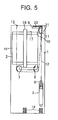
- FIGS. 5 through 8 illustrate an elevator system according to a second embodiment of the present invention.
- FIG. 5 is a longitudinal cross-sectional view conceptually showing an elevator system according to the second embodiment when viewed from the side front;
- FIG. 6 is a longitudinal cross-sectional view of the elevator system shown in FIG. 5 when viewed from the side;
- FIG. 7 is a transverse cross-sectional view showing the principal elements of the elevator system shown in FIG. 5 through 7;
- FIG. 8 is a perspective view of the elevator system shown in FIGS. 5 thorough 7.
- Reference numeral 20 designates a hoisting machine provided on the ceiling of the shaft 1 at a position above a portion of the recessed surface 17 located away from the door 15.
- the drive sheave 6 is provided on the hoisting machine 20 in a rotatable manner such that the rotor axis of the drive sheave 6 is oriented vertically.
- An electric drive motor 21 is provided on the lower surface of the hoisting machine 20 so as to protrude downward within the space between the edge of the car 2 and the interior wall surface of the shaft 1.
- the hoisting machine 20 is disposed on the upper end of the shaft 1, and the lower end of the hoisting machine 20 is located at a position higher than the lower end of the turning pulleys 10 and 11.
- the electric drive motor 21 is attached to the lower surface of the hoisting machine 20 so as to protrude downward, the electric drive motor 21 is located within the space between the edge of the car 2 and the interior wall surface of the shaft 1.
- the hoisting machine 20 is provided on the ceiling of the shaft 1 at a position above a portion of the recessed surface 17 located away from the door 15.
- the car-side turning pulley 10 and the counterweight-side turning pulley 11 are disposed in the gap between the edge of the car 2 and the interior wall surface of the shaft 1. Further detailed description will be omitted to avoid duplication.
- the second embodiment shown in FIGS. 5 through 8 also yields the same advantageous results as those yielded by the first embodiment shown in FIGS. 1 through 4.
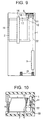
- FIGS. 9 through 11 illustrate an elevator system according to a third embodiment of the present invention.
- FIG. 9 is a longitudinal cross-sectional view conceptually showing an elevator system according to the third embodiment when viewed from the side front;
- FIG. 10 is a transverse cross-sectional view showing the principal elements of the elevator system shown in FIG. 9 ;
- FIG. 11 is a perspective view of the elevator system shown in FIGS. 9 and 10.
- Reference numeral 22 designates a main cable whose one end is connected to the lower edge of the car 2 opposite the door 15 and whose remaining end is connected to the top of the counterweight 3.
- the main cable 22 is wound around the car-side turning pulley 10, the drive sheave 6, and the counterweight-side turning pulley 11, in the sequence given.
- the hoisting machine 18 is disposed on the upper end of the shaft 1, and the lower end of the hoisting machine 18 is located at a position higher than the lower end of the turning pulleys 10 and 11.
- the hoisting machine 18 is provided on the ceiling of the shaft 1 at a position above a portion of the recessed surface 17 located away from the door 15.
- the car-side turning pulley 10 and the counterweight-side turning pulley 11 are disposed within a space between the edge of the car 2 and the interior wall surface of the shaft 1. Consequently, although detailed description will be omitted to avoid duplication, the third embodiment shown in FIGS. 9 through 11 also yields the same advantageous results as those yielded by the first embodiment shown in FIGS. 1 through 4.
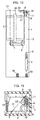
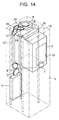
- FIGS. 12 through 14 illustrate an elevator system according to a fourth embodiment of the present invention.
- FIG. 12 is a longitudinal cross-sectional view conceptually showing an elevator system according to the fourth embodiment when viewed from the side front;
- FIG. 13 is a transverse cross-sectional view showing the principal elements of the elevator system shown in FIG. 12;
- FIG. 14 is a perspective view of the elevator system shown in FIGS. 12 and 13.
- Reference numeral 23 designates a deflector wheel mounted on the ceiling of the shaft 1 such that the rotor axis of the deflector wheel 23 is oriented vertically.
- the deflector wheel 23 pulls the main cable 12, which is extending between the drive sheave 6 and the car-side turning pulley 10, toward the interior surface of the shaft 1
- the hoisting machine 18 is disposed on the upper end of the shaft 1, and the lower end of the hoisting machine 18 is located at a position higher than the lower end of the turning pulleys 10 and 11.
- the hoisting machine 18 is provided on the ceiling of the shaft 1 at a position above a portion of the recessed surface 17 located away from the door 15.
- the car-side turning pulley 10 and the counterweight-side turning pulley 11 are disposed within the space between the edge of the car 2 and the interior wall surface of the shaft 1.
- FIGS. 12 through 14 also yields the same advantageous results as those yielded by the first embodiment shown in FIGS. 1 through 4.
- the deflector wheel 23 pulls the main cable 12 extending between the drive sheave 6 and the car-side turning pulley 10, in the horizontal direction toward the interior surface of the shaft 1.
- the side surface of the car-side turning pulley 10 can be provided in parallel with the interior surface of the shaft 1. Consequently, the width of the space between the edge of the car 2 and the interior wall surface of the shaft 1 can be diminished, thus reducing the total space to be occupied by the elevator system within the building to a much greater extent.
- FIGS. 15 through 17 illustrate an elevator system according to a fifth embodiment of the present invention.
- FIG. 15 is a longitudinal cross-sectional view conceptually showing an elevator system according to the fifth embodiment when viewed from the side front;
- FIG. 16 is a transverse cross-sectional view showing the principal elements of the elevator system shown in FIG. 15;
- FIG. 17 is a perspective view of the elevator system shown in FIGS. 15 and 16.
- Reference numeral 24 designates a counterweight provided within the space between the edge of one of the lateral sides of the car 2 and the interior wall surface of the shaft 1.
- the hoisting machine 18 is disposed on the upper end of the shaft 1, and the lower end of the hoisting machine 18 is located at a position higher than the lower end of the turning pulleys 10 and 11.
- the hoisting machine 18 is provided on the ceiling of the shaft 1 at a position above a portion of the recessed surface 17 located away from the door 15.
- the car-side turning pulley 10 and the counterweight-side turning pulley 11 are disposed within the space between the edge of the car 2 and the interior wall surface of the shaft 1.
- the deflector wheel 23 pulls the main cable 12, which is extending between the drive sheave 6 and the car-side turning pulley 10, in the horizontal direction toward the interior surface of the shaft 1.
- the side surface of the car-side turning pulley 10 can be provided in parallel with the interior surface of the shaft 1.
- the fifth embodiment shown in FIGS. 15 through 17 also yields the same advantageous results as those yielded by the fourth embodiment shown in FIGS. 12 through 14.
- the present invention provides an elevator system which comprises a car, a counterweight, turning pulleys, a main cable, and a hoisting machine which includes a drive sheave.
- a car has a door at one end thereof and moves vertically along a predetermined path within a shaft.
- a counterweight is provided within a space between an interior wall surface of the shaft and the car.
- a pair of turning pulleys are provided on the upper end of the shaft in a rotatable manner so as to correspond to the car and the counterweight, respectively, within the space between the car and the interior wall surface of the shaft when viewed within a horizontal plane of projection.
- a main cable is provided and whose one end is connected to the car and whose remaining end is connected to the counterweight.
- the main cable is provided within the shaft and is wound around the turning pulleys.
- a hoisting machine is disposed at the upper end of the shaft and is located at a position higher than the lower edges of the turning pulleys.
- a drive sheave is provided on the hoisting machine in a rotatable manner such that the rotor axis of the drive sheave is oriented vertically.
- the main cable extends between the turning pulleys while being wound around the drive sheave.
- the hoisting machine is disposed at the upper end of the shaft, and the lower end of the hoisting machine is located at a position higher than the lower edges of the turning pulleys.
- the car-side turning pulley and the counterweight-side turning pulley are provided within a space between the edge of the car and the interior wall surface of the shaft.
- the hoisting machine is provided within the shaft accommodated within the height of the top floor of a building, and the main cable can extend between the hoisting machine and the car. Consequently, there is obviated a necessity for making the ceiling of the shaft higher than the top floor of the building, thus diminishing construction cost required for ensuring a space for installing the elevator system.
- the hoisting machine is disposed at a position corresponding to a recess formed in the upper surface of the car as has been described previously.
- the hoisting machine is disposed at the upper end of the shaft, and the lower end of the hoisting machine is located at a position higher than the lower edges of the turning pulleys. Further, the hoisting machine is placed at a position corresponding to a recess formed in the upper surface of the car.
- the car-side turning pulley and the counterweight-side turning pulley are provided within the space between the edge of the car and the interior wall surface of the shaft.
- the hoisting machine is provided within the shaft accommodated within the height of the top floor of a building, and the main cable can extend between the hoisting machine and the car. Consequently, there is obviated a necessity for making the ceiling of the shaft higher than the top floor of the building, thus diminishing construction cost required for ensuring a space for installing the elevator system.
- an electric motor is provided on the hoisting machine so as to protrude downward from the lower surface of the hoisting machine and within the space between the edge of the car and the interior wall surface of the shaft as has been described previously.
- the hoisting machine is disposed at the upper end of the shaft, and the lower end of the hoisting machine is located at a position higher than the lower edges of the turning pulleys.
- the electric motor is provided on the hoisting machine so as to protrude downward from the lower surface of the hoisting machine and provided within the space between the edge of the car and the interior wall surface of the shaft, and the car-side turning pulley and the counterweight-side turning pulley are provided within the space between the edge of the car and the interior wall surface of the shaft.
- the hoisting machine is provided within the shaft accommodated within the height of the top floor of a building, and the main cable can extend between the hoisting machine and the car. Consequently, there is obviated a necessity for making the ceiling of the shaft higher than the top floor of the building, thus diminishing construction cost required for ensuring a space for installing the elevator system.
- a deflector wheel is provided on the roof of the shaft in a rotatable manner such that the rotor axis of the deflector wheel is oriented vertically.
- the deflector wheel pulls the main cable extending between the drive sheave and the turning pulley in a direction toward the interior wall surface of the shaft as has been described previously.
- the hoisting machine is disposed at the upper end of the shaft, and the lower end of the hoisting machine is located at a position higher than the lower edges of the turning pulleys.
- the car-side turning pulley and the counterweight-side turning pulley are provided in a space between the edge of the car and the interior wall surface of the shaft.
- the hoisting machine is provided within the shaft accommodated within the height of the top floor of a building, and the main cable can extend between the hoisting machine and the car. Consequently, there is obviated a necessity for making the ceiling of the shaft higher than the top floor of the building, thus diminishing construction cost required for ensuring a space for installing the elevator system.
- the deflector wheel pulls the main cable extending between the drive sheave and the car-side turning pulley, such that the main cable runs in the direction parallel with the interior surface of the shaft.
- the side surface of the car-side turning pulley can be provided in horizontal direction parallel with the interior surface of the shaft. Consequently, the width of the space between the edge of the car and the interior wall surface of the shaft can be diminished.
- the present invention yields an advantage of reducing the space to be occupied by the elevator system within the building to a much greater extent and of diminishing construction cost required for ensuring the total space for installing the elevator system.
- the drive sheave is provided on the hoisting machine such that the side surface of the drive sheave faces the ceiling of the shaft as has been described previously.
- the hoisting machine is disposed at the upper end of the shaft, and the lower end of the hoisting machine is located at a position higher than the lower edges of the turning pulleys.
- the car-side turning pulley and the counterweight-side turning pulley are provided within the space between the edge of the car and the interior wall surface of the shaft.
- the hoisting machine is provided within the shaft accommodated within the height of the top floor of a building, and the main cable can extend between the hoisting machine and the car. Consequently, there is obviated a necessity for making the ceiling of the shaft higher than the top floor of the building, thus diminishing construction cost required for ensuring a space for installing the elevator system.
- the highest position of the car where the car avoids the hoisting machine may be set higher than in a case where the drive sheave is provided below the hoisting machine. Consequently, the space in the upper end of the shaft can be effectively utilized, and construction cost required for building the shaft can be diminished.
- the hoisting machine and the car overlap at least partially when viewed within a horizontal plane of projection as has been described previously.
- the hoisting machine is disposed at the upper end of the shaft, and the lower end of the hoisting machine is located at a position higher than the lower edges of the turning pulleys.
- the car-side turning pulley and the counterweight-side turning pulley are provided within the space between the edge of the car and the interior wall surface of the shaft.
- the hoisting machine is provided within the shaft accommodated within the height of the top floor of a building, and the main cable can extend between the hoisting machine and the car. Consequently, there is obviated a necessity for making the ceiling of the shaft higher than the top floor of the building, thus diminishing construction cost required for ensuring a space for installing the elevator system.
- the hoisting machine and the car overlap at least partially when viewed within a horizontal plane of projection. The space of the shaft when viewed within a horizontal plane of projection can be effectively utilized, thereby diminishing construction cost required for building the shaft.
Landscapes
- Engineering & Computer Science (AREA)
- Civil Engineering (AREA)
- Mechanical Engineering (AREA)
- Structural Engineering (AREA)
- Lift-Guide Devices, And Elevator Ropes And Cables (AREA)
- Cage And Drive Apparatuses For Elevators (AREA)
Abstract
Description
Claims (6)
- An elevator system comprising:a car which moves vertically along a predetermined path within a shaft;a counterweight provided in a space between an interior wall surface of said shaft and said car;a pair of turning pulleys which are provided on the upper end of the shaft so as to correspond to said car and said counterweight respectively, said pair of turning pulleys being provided, in a horizontal plane of projection, within the space between said car and the interior wall surface of the shaft;a hoisting machine including a drive sheave provided thereon with the rotor axis thereof oriented vertically, said hoisting machine being disposed at the upper end of the shaft and is located at a position higher than the lower edges of said pair of turning pulleys; anda main cable whose one end is connected to said car and whose remaining end is connected to said counterweight, said main cable being wound around said pair of turning pulleys; said main cable extending between said pair of turning pulleys while being wound around said drive sheave.
- The elevator system according to claim 1, wherein said hoisting machine is disposed at a position corresponding to a recess formed in the upper surface of said car.
- The elevator system according to claim 1 or 2, wherein an electric drive motor is provided on said hoisting machine so as to protrude downward from the lower surface of said hoisting machine and within the space between the edge of said car and the interior wall surface of the shaft.
- The elevator system according to either of claims 1 to 3, further comprising a deflector wheel which is provided on the ceiling of the shaft in a rotatable manner such that the rotor axis of said deflector wheel is oriented vertically, said deflector wheel pulling the main cable extending between said drive sheave and said turning pulley in a horizontal direction toward the interior wall surface of the shaft.
- The elevator system according to either of claims 1 to 4, wherein said drive sheave is provided in the upper portion of said hoisting machine such that the upper side surface of said drive sheave faces the ceiling of the shaft.
- The elevator system according to either of claims 1 to 5, wherein said hoisting machine and said car overlap at least partially in a horizontal plane of projection.
Applications Claiming Priority (4)
| Application Number | Priority Date | Filing Date | Title |
|---|---|---|---|
| JP264799 | 1999-01-08 | ||
| JP264799 | 1999-01-08 | ||
| JP23167399 | 1999-08-18 | ||
| JP23167399A JP4191331B2 (en) | 1999-01-08 | 1999-08-18 | Elevator equipment |
Publications (3)
| Publication Number | Publication Date |
|---|---|
| EP1018480A2 true EP1018480A2 (en) | 2000-07-12 |
| EP1018480A3 EP1018480A3 (en) | 2001-02-28 |
| EP1018480B1 EP1018480B1 (en) | 2004-08-04 |
Family
ID=26336092
Family Applications (1)
| Application Number | Title | Priority Date | Filing Date |
|---|---|---|---|
| EP00100130A Expired - Lifetime EP1018480B1 (en) | 1999-01-08 | 2000-01-07 | Cable guide and drive machinery position for elevator |
Country Status (5)
| Country | Link |
|---|---|
| EP (1) | EP1018480B1 (en) |
| JP (1) | JP4191331B2 (en) |
| KR (1) | KR100330286B1 (en) |
| CN (1) | CN1094887C (en) |
| DE (1) | DE60012588T2 (en) |
Cited By (16)
| Publication number | Priority date | Publication date | Assignee | Title |
|---|---|---|---|---|
| WO2002016247A1 (en) | 2000-08-21 | 2002-02-28 | Mitsubishi Denki Kabushiki Kaisha | Elevator device |
| WO2002018257A1 (en) | 2000-08-29 | 2002-03-07 | Mitsubishi Denki Kabushiki Kaisha | Elevator device |
| WO2002018256A1 (en) | 2000-08-28 | 2002-03-07 | Mitsubishi Denki Kabushiki Kaisha | Elevator device |
| WO2002022486A1 (en) | 2000-09-12 | 2002-03-21 | Mitsubishi Denki Kabushiki Kaisha | Elevator device |
| WO2002024566A1 (en) * | 2000-09-20 | 2002-03-28 | Mitsubishi Denki Kabushiki Kaisha | Elevator device |
| WO2002098782A1 (en) | 2001-06-04 | 2002-12-12 | Mitsubishi Denki Kabushiki Kaisha | Elevator device |
| WO2004022471A1 (en) | 2002-09-03 | 2004-03-18 | Mitsubishi Denki Kabushiki Kaisha | Elevator device |
| EP1400478A1 (en) * | 1999-06-03 | 2004-03-24 | Mitsubishi Denki Kabushiki Kaisha | Elevator system |
| EP1422184A3 (en) * | 2002-11-19 | 2004-07-07 | Bravo S.r.l. | Machine-room-less elevator |
| DE102005002607A1 (en) * | 2005-01-20 | 2006-08-10 | System Antriebstechnik Dresden Gmbh | Elevator, with a cabin riding between guide rails, has the machine and emergency brake in a cube structure mounted at the top of the shaft with an angle carrier at the shaft wall and roof |
| CN100528728C (en) * | 2004-09-30 | 2009-08-19 | 三菱电机株式会社 | Elevator device |
| EP1422183A4 (en) * | 2001-08-29 | 2010-06-16 | Mitsubishi Electric Corp | ELEVATOR |
| EP1514827A4 (en) * | 2002-06-14 | 2011-03-23 | Toshiba Elevator Kk | Machine-room-less elevator |
| WO2011072113A1 (en) * | 2009-12-09 | 2011-06-16 | Thyssenkrupp Elevator Capital Corporation | Elevator apparatus yielding no reverse rope bend |
| CN108861966A (en) * | 2018-07-06 | 2018-11-23 | 宁波宏大电梯有限公司 | It is a kind of with the knapsack type elevator for wrapping up in plastic steel wire rope |
| WO2018163143A3 (en) * | 2018-05-22 | 2018-11-29 | Universidad Tecnológica De Panamá | Modular mobile table for prestressing |
Families Citing this family (15)
| Publication number | Priority date | Publication date | Assignee | Title |
|---|---|---|---|---|
| JP2001039643A (en) * | 1999-08-03 | 2001-02-13 | Teijin Seiki Co Ltd | Elevator equipment |
| CN100340466C (en) * | 2000-09-20 | 2007-10-03 | 三菱电机株式会社 | Elevator device |
| JP4849712B2 (en) * | 2000-11-08 | 2012-01-11 | 東芝エレベータ株式会社 | elevator |
| JP4825368B2 (en) * | 2001-07-10 | 2011-11-30 | 東芝エレベータ株式会社 | Elevator equipment |
| WO2004005177A1 (en) * | 2002-07-08 | 2004-01-15 | Mitsubishi Denki Kabushiki Kaisha | Elevator device |
| CN1612837A (en) * | 2002-12-24 | 2005-05-04 | 三菱电机株式会社 | Elevator device |
| DE60333795D1 (en) * | 2003-03-12 | 2010-09-23 | Mitsubishi Electric Corp | LIFT DEVICE |
| JPWO2005056455A1 (en) * | 2003-12-09 | 2007-07-05 | 三菱電機株式会社 | Elevator equipment |
| EP1710196B1 (en) | 2004-01-27 | 2012-08-08 | Mitsubishi Denki Kabushiki Kaisha | Drive unit for elevator apparatus, elevator apparatus, installation method of elevator apparatus, and maintenance/inspection method of elevator apparatus |
| EP1862420B1 (en) * | 2005-03-04 | 2014-06-04 | Mitsubishi Denki Kabushiki Kaisha | Elevator apparatus |
| KR101016822B1 (en) * | 2006-05-19 | 2011-02-21 | 미쓰비시덴키 가부시키가이샤 | Elevator device |
| WO2008026263A1 (en) * | 2006-08-30 | 2008-03-06 | Mitsubishi Electric Corporation | Elevator device |
| KR100795265B1 (en) * | 2006-09-20 | 2008-01-15 | 미쓰비시덴키 가부시키가이샤 | Elevator device |
| DE102008022709A1 (en) * | 2008-05-07 | 2009-11-19 | Thyssenkrupp Steel Ag | Use of a metallic composite material in a vehicle structure |
| CN114772416B (en) * | 2022-04-11 | 2023-08-25 | 天津市特种设备监督检验技术研究院(天津市特种设备事故应急调查处理中心) | Automatic disinfection and epidemic prevention elevator |
Family Cites Families (3)
| Publication number | Priority date | Publication date | Assignee | Title |
|---|---|---|---|---|
| CH666673A5 (en) * | 1985-05-10 | 1988-08-15 | Gebauer Ag | Drive for lifts and method of assembly. |
| ES2227012T3 (en) * | 1996-11-11 | 2005-04-01 | Inventio Ag | ELEVATOR INSTALLATION WITH MOTOR UNIT DISPOSED IN THE ELEVATOR BOX. |
| EP0841283B1 (en) * | 1996-11-11 | 2003-04-16 | Inventio Ag | Elevator system with the drive machinery unit arranged inside the hoistway |
-
1999
- 1999-08-18 JP JP23167399A patent/JP4191331B2/en not_active Expired - Fee Related
- 1999-12-29 KR KR1019990064603A patent/KR100330286B1/en not_active Expired - Fee Related
-
2000
- 2000-01-07 DE DE60012588T patent/DE60012588T2/en not_active Expired - Lifetime
- 2000-01-07 EP EP00100130A patent/EP1018480B1/en not_active Expired - Lifetime
- 2000-01-07 CN CN00100931A patent/CN1094887C/en not_active Expired - Fee Related
Cited By (27)
| Publication number | Priority date | Publication date | Assignee | Title |
|---|---|---|---|---|
| EP1400478A1 (en) * | 1999-06-03 | 2004-03-24 | Mitsubishi Denki Kabushiki Kaisha | Elevator system |
| JP4675548B2 (en) * | 2000-08-21 | 2011-04-27 | 三菱電機株式会社 | Elevator equipment |
| EP1312573A4 (en) * | 2000-08-21 | 2008-09-03 | Mitsubishi Electric Corp | LIFT FACILITY |
| WO2002016247A1 (en) | 2000-08-21 | 2002-02-28 | Mitsubishi Denki Kabushiki Kaisha | Elevator device |
| WO2002018256A1 (en) | 2000-08-28 | 2002-03-07 | Mitsubishi Denki Kabushiki Kaisha | Elevator device |
| EP1327596A4 (en) * | 2000-08-28 | 2008-09-03 | Mitsubishi Electric Corp | ELEVATOR DEVICE |
| WO2002018257A1 (en) | 2000-08-29 | 2002-03-07 | Mitsubishi Denki Kabushiki Kaisha | Elevator device |
| EP1314680A4 (en) * | 2000-08-29 | 2008-09-03 | Mitsubishi Electric Corp | ELEVATOR DEVICE |
| JPWO2002022486A1 (en) * | 2000-09-12 | 2004-01-22 | 三菱電機株式会社 | Elevator equipment |
| WO2002022486A1 (en) | 2000-09-12 | 2002-03-21 | Mitsubishi Denki Kabushiki Kaisha | Elevator device |
| EP1319627A4 (en) * | 2000-09-12 | 2008-09-03 | Mitsubishi Electric Corp | ELEVATOR DEVICE |
| EP2042462A1 (en) * | 2000-09-12 | 2009-04-01 | Mitsubishi Denki Kabushiki Kaisha | Elevator apparatus |
| WO2002024566A1 (en) * | 2000-09-20 | 2002-03-28 | Mitsubishi Denki Kabushiki Kaisha | Elevator device |
| EP1972591A3 (en) * | 2000-09-20 | 2008-10-15 | Mitsubishi Denki Kabushiki Kaisha | Elevator apparatus |
| EP1396457A4 (en) * | 2001-06-04 | 2010-02-17 | Mitsubishi Electric Corp | LIFT DEVICE |
| WO2002098782A1 (en) | 2001-06-04 | 2002-12-12 | Mitsubishi Denki Kabushiki Kaisha | Elevator device |
| EP1422183A4 (en) * | 2001-08-29 | 2010-06-16 | Mitsubishi Electric Corp | ELEVATOR |
| EP1514827A4 (en) * | 2002-06-14 | 2011-03-23 | Toshiba Elevator Kk | Machine-room-less elevator |
| EP1535875A4 (en) * | 2002-09-03 | 2011-04-06 | Mitsubishi Electric Corp | ELEVATOR DEVICE |
| WO2004022471A1 (en) | 2002-09-03 | 2004-03-18 | Mitsubishi Denki Kabushiki Kaisha | Elevator device |
| EP1422184A3 (en) * | 2002-11-19 | 2004-07-07 | Bravo S.r.l. | Machine-room-less elevator |
| CN100528728C (en) * | 2004-09-30 | 2009-08-19 | 三菱电机株式会社 | Elevator device |
| DE102005002607A1 (en) * | 2005-01-20 | 2006-08-10 | System Antriebstechnik Dresden Gmbh | Elevator, with a cabin riding between guide rails, has the machine and emergency brake in a cube structure mounted at the top of the shaft with an angle carrier at the shaft wall and roof |
| WO2011072113A1 (en) * | 2009-12-09 | 2011-06-16 | Thyssenkrupp Elevator Capital Corporation | Elevator apparatus yielding no reverse rope bend |
| WO2018163143A3 (en) * | 2018-05-22 | 2018-11-29 | Universidad Tecnológica De Panamá | Modular mobile table for prestressing |
| CN108861966A (en) * | 2018-07-06 | 2018-11-23 | 宁波宏大电梯有限公司 | It is a kind of with the knapsack type elevator for wrapping up in plastic steel wire rope |
| CN108861966B (en) * | 2018-07-06 | 2024-03-19 | 宁波宏大电梯有限公司 | Knapsack formula elevator with wrap up in plastic wire rope |
Also Published As
| Publication number | Publication date |
|---|---|
| CN1260319A (en) | 2000-07-19 |
| CN1094887C (en) | 2002-11-27 |
| DE60012588T2 (en) | 2005-08-04 |
| DE60012588D1 (en) | 2004-09-09 |
| EP1018480A3 (en) | 2001-02-28 |
| EP1018480B1 (en) | 2004-08-04 |
| JP2000255933A (en) | 2000-09-19 |
| KR20000052619A (en) | 2000-08-25 |
| JP4191331B2 (en) | 2008-12-03 |
| KR100330286B1 (en) | 2002-03-27 |
Similar Documents
| Publication | Publication Date | Title |
|---|---|---|
| EP1018480B1 (en) | Cable guide and drive machinery position for elevator | |
| EP1031528B1 (en) | Elevator system | |
| EP1149042B1 (en) | Traction sheave elevator | |
| KR100966534B1 (en) | Elevator system with multiple cars in hoistway | |
| EP1557391B1 (en) | Positioning of a hoisting machine | |
| EP1396460B1 (en) | Elevator system | |
| EP1471026A9 (en) | Elevator device | |
| JP4255523B2 (en) | Elevator | |
| EP1172321B1 (en) | Elevator device | |
| CN100497147C (en) | Elevator device | |
| US7562745B2 (en) | Elevator with an operation space in a center of a machine room | |
| EP1396457A1 (en) | Elevator device | |
| EP1327596B1 (en) | Elevator device | |
| EP1010661B1 (en) | Elevator | |
| CN110546098B (en) | elevator installation | |
| EP1556304B1 (en) | Elevator | |
| EP1057769B1 (en) | Elevator | |
| EP1724229A1 (en) | Elevator apparatus | |
| JP5056672B2 (en) | Elevator equipment | |
| JP4841211B2 (en) | Elevator car door drive | |
| JPH043791A (en) | Linear motor-driven elevator | |
| EP1520830A1 (en) | Elevator device | |
| JP2004051250A (en) | Elevator equipment | |
| JPH07112883A (en) | Linear motor elevator | |
| CN101428724A (en) | Elevator apparatus |
Legal Events
| Date | Code | Title | Description |
|---|---|---|---|
| PUAI | Public reference made under article 153(3) epc to a published international application that has entered the european phase |
Free format text: ORIGINAL CODE: 0009012 |
|
| 17P | Request for examination filed |
Effective date: 20000107 |
|
| AK | Designated contracting states |
Kind code of ref document: A2 Designated state(s): DE FR NL |
|
| AX | Request for extension of the european patent |
Free format text: AL;LT;LV;MK;RO;SI |
|
| PUAL | Search report despatched |
Free format text: ORIGINAL CODE: 0009013 |
|
| AK | Designated contracting states |
Kind code of ref document: A3 Designated state(s): DE FR NL |
|
| AX | Request for extension of the european patent |
Free format text: AL;LT;LV;MK;RO;SI |
|
| AKX | Designation fees paid |
Free format text: DE FR NL |
|
| 17Q | First examination report despatched |
Effective date: 20030327 |
|
| GRAP | Despatch of communication of intention to grant a patent |
Free format text: ORIGINAL CODE: EPIDOSNIGR1 |
|
| GRAS | Grant fee paid |
Free format text: ORIGINAL CODE: EPIDOSNIGR3 |
|
| GRAA | (expected) grant |
Free format text: ORIGINAL CODE: 0009210 |
|
| AK | Designated contracting states |
Kind code of ref document: B1 Designated state(s): DE FR NL |
|
| REF | Corresponds to: |
Ref document number: 60012588 Country of ref document: DE Date of ref document: 20040909 Kind code of ref document: P |
|
| PLBE | No opposition filed within time limit |
Free format text: ORIGINAL CODE: 0009261 |
|
| STAA | Information on the status of an ep patent application or granted ep patent |
Free format text: STATUS: NO OPPOSITION FILED WITHIN TIME LIMIT |
|
| 26N | No opposition filed |
Effective date: 20050506 |
|
| EN | Fr: translation not filed | ||
| ET | Fr: translation filed | ||
| REG | Reference to a national code |
Ref country code: FR Ref legal event code: ERR Free format text: BOPI DE PUBLICATION N: 05/30 PAGES: 234 PARTIE DU BULLETIN CONCERNEE: BREVETS EUROPEENS DONT LA TRADUCTION N'A PAS ETE REMISE A I'INPI IL Y A LIEU DE SUPPRIMER: LA MENTION DE LA NON REMISE. LA REMISE DE LA TRADUCTION EST PUBLIEE DANS LE PRESENT BOPI. |
|
| PGFP | Annual fee paid to national office [announced via postgrant information from national office to epo] |
Ref country code: FR Payment date: 20100208 Year of fee payment: 11 |
|
| REG | Reference to a national code |
Ref country code: NL Ref legal event code: V1 Effective date: 20110801 |
|
| REG | Reference to a national code |
Ref country code: FR Ref legal event code: ST Effective date: 20110930 |
|
| PG25 | Lapsed in a contracting state [announced via postgrant information from national office to epo] |
Ref country code: FR Free format text: LAPSE BECAUSE OF NON-PAYMENT OF DUE FEES Effective date: 20110131 |
|
| PG25 | Lapsed in a contracting state [announced via postgrant information from national office to epo] |
Ref country code: NL Free format text: LAPSE BECAUSE OF NON-PAYMENT OF DUE FEES Effective date: 20110801 |
|
| PGFP | Annual fee paid to national office [announced via postgrant information from national office to epo] |
Ref country code: NL Payment date: 20100131 Year of fee payment: 11 |
|
| PGFP | Annual fee paid to national office [announced via postgrant information from national office to epo] |
Ref country code: DE Payment date: 20151229 Year of fee payment: 17 |
|
| REG | Reference to a national code |
Ref country code: DE Ref legal event code: R084 Ref document number: 60012588 Country of ref document: DE |
|
| REG | Reference to a national code |
Ref country code: DE Ref legal event code: R119 Ref document number: 60012588 Country of ref document: DE |
|
| PG25 | Lapsed in a contracting state [announced via postgrant information from national office to epo] |
Ref country code: DE Free format text: LAPSE BECAUSE OF NON-PAYMENT OF DUE FEES Effective date: 20170801 |