EP1018232B1 - Protection inegale contre les erreurs dans des schemas de modulation codes - Google Patents
Protection inegale contre les erreurs dans des schemas de modulation codes Download PDFInfo
- Publication number
- EP1018232B1 EP1018232B1 EP98949438A EP98949438A EP1018232B1 EP 1018232 B1 EP1018232 B1 EP 1018232B1 EP 98949438 A EP98949438 A EP 98949438A EP 98949438 A EP98949438 A EP 98949438A EP 1018232 B1 EP1018232 B1 EP 1018232B1
- Authority
- EP
- European Patent Office
- Prior art keywords
- code
- bits
- coded
- decoding
- stream
- Prior art date
- Legal status (The legal status is an assumption and is not a legal conclusion. Google has not performed a legal analysis and makes no representation as to the accuracy of the status listed.)
- Expired - Lifetime
Links
Images


Classifications
-
- H—ELECTRICITY
- H04—ELECTRIC COMMUNICATION TECHNIQUE
- H04L—TRANSMISSION OF DIGITAL INFORMATION, e.g. TELEGRAPHIC COMMUNICATION
- H04L1/00—Arrangements for detecting or preventing errors in the information received
- H04L1/004—Arrangements for detecting or preventing errors in the information received by using forward error control
- H04L1/0056—Systems characterized by the type of code used
- H04L1/0057—Block codes
- H04L1/0058—Block-coded modulation
-
- H—ELECTRICITY
- H04—ELECTRIC COMMUNICATION TECHNIQUE
- H04L—TRANSMISSION OF DIGITAL INFORMATION, e.g. TELEGRAPHIC COMMUNICATION
- H04L1/00—Arrangements for detecting or preventing errors in the information received
- H04L1/004—Arrangements for detecting or preventing errors in the information received by using forward error control
- H04L1/0041—Arrangements at the transmitter end
-
- H—ELECTRICITY
- H04—ELECTRIC COMMUNICATION TECHNIQUE
- H04L—TRANSMISSION OF DIGITAL INFORMATION, e.g. TELEGRAPHIC COMMUNICATION
- H04L1/00—Arrangements for detecting or preventing errors in the information received
- H04L1/004—Arrangements for detecting or preventing errors in the information received by using forward error control
- H04L1/0056—Systems characterized by the type of code used
- H04L1/007—Unequal error protection
Definitions
- This invention relates to coded modulation schemes used in communication systems and more particularly to the use of product codes and other concatenated codes in coded modulation schemes.
- Coded modulations such as multi-level coding or block coded modulation (BCM) can be used to increase the information rate (spectral efficiency) of a communication system without decreasing power efficiency.
- This increase in the information rate is useful in a communication system in which speech signals are digitized and compressed before being transmitted. Higher compression saves bandwidth, but reproduction quality suffers under adverse conditions in the communication channel.
- the increased information rate with coded modulation permits less compression to be used, and hence reproduction quality can be improved.
- a greater information rate i.e., a greater information capacity, also enables a communication system to accommodate more users.
- Multi-level coding schemes such as BCM are described in H. Imai et al., "A New Multi-Level Coding Method Using Error Correcting Codes", IEEE Transactions on Information Theory vol. IT-23, pp. 371-377 (May 1977); S. Sayegh, "A Class of Optimum Block Codes in Signal Space", IEEE Transactions on Communications vol. COM-34, pp. 1043-45 (Oct. 1986); A.R. Calderbank, “Multi-Level Codes and MultiStage Decoding", IEEE Transactions on Communications vol. COM-37, pp. 222-229 (Mar. 1989); G.
- This article relates generally to improvements in the DER of multistage decoding using interleaving between the levels, pass reliability information between the different stages by applying "Soft-Output" decoders, and the application of reiterated decoding.
- the Viterbi algorithm is used for decoding, the estimated information bit sequence is liable to contain error bursts. This sequence is re-encoded and fed into the decoder of the next level. Thus, the re-encoded sequence also contains error bursts. If this decoder also uses the Viterbi algorithm then it is very sensitive to these error bursts, because the algorithm is designed to deal with independent errors in the input stream. Thus, the performance of this decoder is mostly determined by preceding decoders.
- interleaving between the coded bit streams of each level.
- An interleaver matrix is added to the coder block diagram between the coders of each level and the mapping unit.
- the received symbols are first written into a deinterleaver matrix and are then processed.
- the interleaving has to be done in such a way that the re-encoded bit streams of any two decoders are spread for the third decoder. So it will be hardly influenced by error bursts from any of the other two decoders.
- Multi-level BCM is an attractive scheme for combined modulation and coding, particularly for Rayleigh fading environments where interleaving depth is a crucial factor in determining the bit error rate (BER) performance.
- US 5,416,804 describes apparatus for decoding digital signals, such as digital television signals, which have been transmitted by concatenated coded modulation using partitioning levels of a constellation of points representing different code values.
- the apparatus includes successive decoding stages which respectively operate on the successive partitioning levels of the constellation.
- Each decoding stage includes a detector for detecting received points in the relevant partitioning level.
- At least one stage includes an internal decoder for generating estimated bit sequences in accordance with an inner code and erasures of bit sequences for which the estimation is found to be ambiguous, an external decoder decoding in accordance with an outer code and correcting bit sequence erasures, and an encoder for encoding the output of the external decoder and supplying the resulting re-encoded bit sequences to the succeeding stages of the decoding apparatus to validate detection thereby of points in their partitioning levels.
- the apparatus may be arranged to produce only a predetermined maximum number of erased bit sequences.
- EP 0,490,552 relates to an arrangement whereby unequal error protection is provided for an HDTV signal by separately coding each one of the classes of information in the HDTV signal by using a conventional coded modulation scheme and then time-division-multiplexing the various coded outputs for transmission.
- US 5,581,481 relates to a storage and retrieval system for JPEG images.
- the system includes an apparatus for storing a JPEG image in or on a storage medium with unequal error protection, comprising a separator for separating the JPEG image into Type-I and Type-II information, an error correction encoder for encoding the Type-I information with more error protection than the Type-II information, and a storage recorder for recording the encoded Type-I and Type-II information in or on the storage medium.
- the system further includes an apparatus for reading the encoded Type-I and Type-II information from the storage medium.
- US 5,349,589 describes a method and apparatus for digital radio communication employs separation of a frame of data to be transmitted into key bits, critical bits and unprotected bits.
- the key bits are processed to provide parity bits.
- the parity bits, and key bits are convolutionally encoded using a tail-biting scheme and merged with unprotected bits, and then transmitted.
- the decoder splits the received data into convolutionally encoded bits and unprotected bits, and trellis decodes the convolutionally encoded bits into a number of possible paths through a trellis using a generalized Viterbi algorithm.
- the tail-biting scheme reduces the number of bits that must be transmitted. Paths having errors in the key bits are rejected, and the path having the best metric without key bit errors is used in decoding the transmitted information. In the event that there is no such path, a previously selected path is substituted and decoded.
- US 4,802,171 concerns a system and method for error correction in communication systems for transmission of digitized speech signals.
- Sub-band coding is preferably applied to the input signal, and the sample information and the side information provided.
- An error detection code (EDC) is applied to at least a portion of the side information and an error correction code (ECC) is applied over the side information and the EDC.
- EDC error correction code
- a second EDC is applied to the ECC.
- first information of k 1 x k 2 digits having k 1 digits in a first direction and k 2 digits in a second direction is encoded into a product code C A of n 1 x n 2 digits by combining a partial code word C 1 expressed in a linear (n 1 , k 1 , d 1 ) code having a minimum distance d 1 in the first direction with a partial code word C 2 expressed in a linear (n 2 , k 2 , d 2 ), code having a minimum distance d 2 in the second direction;
- second information of r x k x (r ⁇ n 1 - k 1 , k x ⁇ n 2 ) digits is encoded into a code U s of a linear (n 2 , k x , d 3 ) code having a minimum distance d 3 in the second direction;
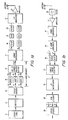
- FIG. 1a A transmitter using BCM and eight-point phase-shift keying (8-PSK) modulation is shown in Fig. 1a, in which a speech or other information source 11 generates an analog signal representing the speech or other information.
- the continuous analog speech signal is converted into a stream of digital data, such as binary bits, by a digitizer 12, such as an analog to digital converter, from which the digital data passes to a speech encoder 13.
- the speech encoder 13 transforms the digital data from the digitizer 12 into a plurality of streams i 0 , i 1 , i 2 , ... of encoded digital data elements, each stream representing a respective subset of the information in the information signal.
- this 8-PSK example there are three such streams i 0 , i 1 , i 2 , although it will be understood that an M-ary modulation other than 8-PSK, such as 16-PSK or 16 - ary quadrature amplitude modulation (QAM), and other than three streams i of encoded digital data elements might be used.
- At least one of the streams of encoded data elements represents information in the speech signal that is more important than the information represented by the other streams.
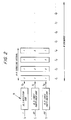
- the streams i 0 , i 1 , i 2 are provided as inputs to a BCM encoder 14, which includes a plurality of block encoders 15 connected in parallel and a bits-to-symbol mapper 16.
- the input streams are encoded according to respective block codes C 0 , C 1 , C 2 , yielding respective output streams of codewords comprising respective streams b 0 , b 1 , b 2 of coded bits.
- the code C 0 be the most powerful code, followed by the code C 1 and then the code C 2 .
- the bit stream i 0 would represent the most important class of information, which may be called Class 0; the bit stream i 1 would represent the next most important class, which may be called Class 1; and the bit stream i 2 would represent the least important class, which may be called Class 2.
- Each of the succession of triplets of code bits ⁇ b 2 b 1 b 0 ⁇ produced by the block encoders 15 is used by the mapper 16 to select a respective one of the constellation of eight 8-PSK symbols according to a predetermined scheme.
- b 2 is the most significant bit (MSB)
- b 0 is the least significant bit (LSB).
- a conventional bits-to-symbol mapper which may be realized as a lookup table or as a combination of logic elements, uses either natural binary mapping or Gray coded mapping. In this way, three N-bit block codewords generated by the three block encoders 15 are transformed into one modulation codeword, comprising N modulation symbols.
- the bits-to-symbol mapper 16 produces a stream of generally complex-valued (I + jQ) modulation symbols that is provided to a symbol interleaver 17, which shuffles the order of the modulation symbols, separating formerly successive symbols in time. Interleaving helps spread the effect of noise and other impairments in the physical communication channel among the modulation symbols, minimizing the chances that all of the symbols of a codeword will be affected and taking advantage of the built-in time diversity of the multi-level block code.
- the symbol interleaver 17 also separates the interleaved symbols into in-phase (I) and quadrature (Q) components, which undergo pulse-shaping by filters 18, and the filtered components are then converted from digital to analog form by D/A converters 19.
- the analog signals are further spectrally shaped by filters 20, and the filter output signals are applied to an I, Q modulator 21, which quadrature modulates a carrier signal with those signals.
- the modulated carrier signal is then amplified by a suitable amplifier 22, and the amplified carrier signal is transmitted via an antenna 23.
- the modulated carrier signal collected by an antenna 25 is selected by a suitable bandpass filter 26 and amplified by a suitable amplifier 27.
- the amplified signal is then translated in frequency by a down-converter 28, which is typically a balanced mixer and suitable oscillator, either directly to baseband or as illustrated to an intermediate frequency (IF) and then the IF signal is translated to baseband by an IF down-converter 29.
- the baseband signal comprises I' and Q' components, which are converted from analog to digital form by A/D converters 30.
- the digitized I' and Q' components are then provided to a sample timing selector 31, the output of which is a stream of complex-valued 8-PSK modulation symbols that is provided to a de-interleaver 32.
- the de-interleaver 32 reverses the shuffling performed by the symbol interleaver 17 and generates a stream of modulation symbols that is identical to the stream generated by the bits-to-symbol mapper 16.
- the de-interleaved symbols produced by the de-interleaver 32 are applied to a BCM decoder 33, which transforms the de-interleaved symbols into parallel data symbol streams i 0 , i 1 , i 2 .
- the data symbol streams are then applied to a speech decoder 34, which reverses the encoding performed by the speech encoder 13 and produces a speech signal.
- the BCM encoder 14 uses the triplets ⁇ b 2 b 1 b 0 ⁇ of block code symbols as addresses for the 8-PSK symbols, which may be stored in a memory at locations identified by the addresses.
- the relationship between the triplets and the modulation symbols is called a "mapping", and typically either natural order binary mapping or Gray code mapping is used.
- Fig. 2 illustrates a BCM encoder 14 in which C 0 is a (4,1) repetition code and C 1 and C 2 are (4,3) single-parity-check codes
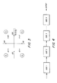
- Fig. 3 illustrates the natural binary mapping of triplets to 8-PSK symbols.
- the block length N of the codes C 0 , C 1 , C 2 is four, and thus four triplets of block code symbols ⁇ 111 ⁇ , ⁇ 100 ⁇ , ⁇ 110 ⁇ , and ⁇ 101 ⁇ are used to select four 8-PSK symbols that compose the BCM codeword ⁇ S 1 S 2 S 3 S 4 ⁇ .
- each class of bits may be encoded by a different code, and thus unequal error protection of the bits can be readily achieved.
- the unequal error protection is useful particularly for speech data, where all the bits are not equally important in a perceptual sense.
- Optimizing a coded modulation scheme to achieve a desired BER performance involves choosing the component codes and the appropriate bits-to-symbol mapping scheme that achieve the desired performance specifications. It is often desirable to improve the BER performance of a specific class of bits without increasing decoding complexity significantly or affecting the BER performance of the other classes of bits.
- a product code can improve the BER performance of a selected class of information in the coded modulation scheme without affecting the decoding complexity or BER performance of other classes of information. Moreover, it is advantageous to pass soft information between decoders of inner and outer codes of a product code.
- a coded modulation method includes the steps of encoding each of a plurality of streams of data bits according to a respective code, thereby generating respective streams of coded bits, and selecting modulation symbols based on respective groups of the coded bits. At least one stream of data bits is encoded according to a product code and at least one other stream of data bits is encoded according to at least one other code. Each group of coded bits used for selecting modulation symbols includes coded bits from all of the streams of coded bits.
- the product code and other code may be block codes having a predetermined block length.
- the encoding step may include the steps of encoding the stream of data bits according to an outer code, thereby generating a stream of outer-code bits, and encoding the stream of outer-code bits according to an inner code, thereby generating a stream of product-code bits.
- the inner code may have the predetermined block length.
- the method may further include the step of interleaving the outer-code bits, wherein the interleaved outer-code bits are encoded according to the inner code.
- the modulation symbols may be phase-shift keying symbols.
- a coded modulator includes a device for encoding each of a plurality of streams of data bits according to a respective code and for generating respective streams of coded bits, and a device for selecting modulation symbols based on respective groups of the coded bits. At least one of the streams of data bits is encoded according to a product code and the remaining streams of data bits are encoded according to at least one other code. Each group includes coded bits from all of the streams of coded bits.
- the inner code of the product code and the other code or codes may be block codes having the a predetermined block length.
- the encoding device may include a device for encoding a stream of data bits according to an outer code, thereby generating a stream of outer-code bits, and a device for encoding the stream of outer-code bits according to an inner code, thereby generating the stream of product-code bits.
- the inner code may have the predetermined block length.
- the encoding device may further include a device for interleaving the outer-code bits thereby generating interleaved outer-code bits, and the interleaved outer-code bits may be encoded according to the inner code.
- the selecting device may include a memory having a plurality of storage locations that are identified by respective addresses. Each modulation symbol may be stored in a respective one of the storage locations, and the selecting device may retrieve modulation symbols stored in storage locations identified by the groups of coded bits.
- a communications apparatus includes a device for generating a plurality of streams of data bits, comprising a first stream of data bits and other streams of data bits; a device for encoding the first stream of data bits according to a product code and for generating a stream of product-code bits; at least one device for encoding the other streams of data bits according to at least one other code and for generating at least one stream of other-code bits; and a device for selecting modulation symbols based on respective groups of the product-code bits and the other-code bits. Each group includes at least one product-code bit and at least one other code bit.
- the communications apparatus further includes a device for interleaving the selected modulation symbols; a device for transmitting a carrier signal modulated by the interleaved selected modulation symbols; and a device for receiving the carrier signal modulated by the interleaved selected modulation symbols and for recovering the interleaved selected modulation symbols.
- the communications apparatus further includes a device for de-interleaving the interleaved selected modulation symbols; and a device for decoding the de-interleaved selected modulation symbols, thereby recovering the plurality of streams of data bits.
- the product coding device may include a device for encoding the stream of data bits according to an outer code, thereby generating a stream of outer-code bits, and a device for encoding the stream of outer-code bits according to an inner code, thereby generating the stream of product-code bits.
- the outer code, inner code, and at least one other code may be block codes.
- the product coding device may further include a device for interleaving the outer-code bits.
- the device for de-interleaving the modulation symbols may include a memory having an array of storage locations that are identified by respective addresses.
- the interleaved modulation symbols may be stored in respective storage locations, and the decoding device may lecode the modulation symbols stored in the memory according to a viterbi algorithm.
- the modulation symbols may be stored in the memory such that all coded bits produced by the inner code are stored in respective rows, and the decoding device, in decoding the coded bits stored in each row, generates soft information that is used in decoding coded bits produced by the outer code.
- the decoding device may utilize an iterative decoding process in which soft information is generated by decoding the coded bits stored in each row, the soft information is used in decoding the coded bits produced by the outer code, and the decoded bits produced by the outer code are used to again decode the coded bits stored in each row.
- T an apparatus for decoding a stream of modulation symbols that respectively represent coded bits, wherein the coded bits are produced by respective codes and wherein at least one of the respective codes is a product code including at least one inner code and at least one outer code.
- the apparatus includes a memory having an array of storage locations that are identified by respective addresses; a device for storing the modulation symbols in respective storage locations; and a device for decoding the modulation symbols stored in the memory according to a viterbi algorithm.
- the modulation symbols are stored in the memory such that all coded bits produced by the at least one inner code are stored in respective rows, and the decoding device, in decoding the coded bits stored in each row, generates soft information that is used in decoding coded bits produced by the outer code.
- the decoding device may utilize an iterative decoding process in which soft information is generated by decoding the coded bits stored in each row, the soft information is used in decoding the coded bits produced by the at least one outer code, and the decoded code bits produced by the at least one outer code are used to again decode the coded bits stored in each row.
- coded bits produced by the at least one outer code may be stored in nonadjacent rows of the memory.
- an analog speech signal may be digitized at a rate of 64 kilobits/second (Kbps) using standard eight-bit pulse code modulation (PCM).
- the digitized speech may then be compressed by a speech encoder according to a speech coding algorithm, and the bits included in the encoded digital speech signal may then be categorized into classes based on their importance in reproduction of the analog speech signal.
- the more important bit classes should be preserved with less distortion or errors, which can arise from transmission of these bits through a communication channel. For example, information sent through a radio channel can suffer from transmitter noise, environmental noise, interference from other channel users, signal strength variations (fading), receiver noise, etc.
- Figs. 1a, 1b, 2, and 3 illustrate a BCM scheme based on 8-PSK modulation with three block codes C 0 , C 1 , C 2 for coding bit classes Class 0, Class 1, Class 2 bits, respectively.
- the speech coder has three bit classes that correspond to the bits' perceptual significance and that are protected by a BCM scheme accordingly, and the following description is in terms of 8-PSK. Nevertheless, it will be appreciated by those of ordinary skill in this art that the invention-is not limited to this example.
- the invention is generally applicable to M-ary modulation schemes, such as M-ary PSK, for which the M modulation symbols would be addressed by M-tuplets ⁇ b M-1 b M-2 ... b 1 b 0 ⁇ .
- the invention is also generally applicable to coding schemes other than block coding and to speech coders having other than three classes.
- the BER performance for a selected class of information such as Class 0 is improved by use of a product code or concatenated code as described below.
- a product code or concatenated code comprises a set of nested codes. As illustrated by Fig. 4, the output is formed by the product of the nested codes code 1, code 2, ..., code N.
- the codes C 0 and C 1 can advantageously be used as the nested codes as described in more detail below. In the BCM scheme illustrated in Fig.
- the BCM encoder 14 illustrated in Figs. 1a and 2 is modified such that the (4,1) repetition code C 0 is replaced with a product code C 0 formed, for example, by the product of the (4,1) repetition code and the (4,3) single-parity-check code.
- the two nested codes can conveniently be identified as an outer code C 0 (O) ) and an inner code C 0 (I) , and the outer code is the (4,3) single-parity-check code and the inner code is the (4,1) repetition code.
- the effective block length of code C 0 is increased (to sixteen, in this example) without increasing the length of the BCM codewords, and thus the Class 0 bits are more heavily protected.
- This advantage is achieved without affecting the system's decoding complexity as far as the codes C 1 and C 2 are concerned.
- the interleaving depth that can be achieved with a finite-size interleaver is not changed.
- a possible disadvantage of using a product code is that the information rate for the selected class of bits is decreased. Depending on the specific application and the particular choice of inner and outer codes, the improvement in BER performance for the selected class may justify the lowering of the information rate.
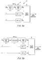
- Fig. 5a illustrates an improved encoder 14' using a product code for a selected class of information in accordance with the invention.
- Class 0 information i 0 is first encoded by an outer encoder 15-1, which produces a stream i 0 ' of outer code bits that passes to an inner encoder 15-2.
- the stream b 0 of product-code bits generated by the inner encoder 15-2 passes, with the code-bit streams b 1 , b 2 produced by respective encoders that encode the Class 1 and Class 2 information streams according to the codes C 1 and C 2 encoders, to the bits-to-symbol mapper 16 (shown in Fig. 1a).
- the bits-to-symbol mapper 16 uses these code-bit streams as addresses for retrieving complex-valued 8-PSK symbols from respective storage locations in a memory.
- the modulation symbols retrieved by the bits-to-symbol mapper 16 are provided to the symbol interleaver 17 (shown in Fig. 1a) for further processing in the manner described above in connection with Fig. 1a.
- FIG. 5b An alternative to the arrangement depicted in Fig. 5a is depicted in Fig. 5b, which shows an additional interleaver 17-1, disposed between the outer-code encoder 15-1 and the inner-code encoder 15-2, for shuffling the outer-code bits.
- This arrangement is advantageous because, as described in more detail below, it helps avoid losing the benefits of the outer code.
- a radio channel may experience fading, which is a decrease in received signal level that, if deep enough, can make decoding very difficult in the presence of receiver noise and interference, increasing the probability of errors due to the decreased signal to noise ratio.
- Fig. 6a illustrates a fade in signal amplitude level and a corresponding portion of a stream of transmitted symbols S 1 , S 2 , S 3 , ... conveyed by the fading signal.
- a fade can affect a large number of consecutive symbols, which without interleaving might be a substantial portion of the symbols of one or more transmitted codewords. (Threee BCM codewords, each comprising four symbols S, are indicated in Fig. 6a.) If too many of its symbols are received with poor signal to noise ratio, a codeword may not be decoded correctly.
- Interleaving shuffles the stream of symbols so that the symbols composing a given codeword are spaced far enough apart that they are unlikely to be affected by the same fade.
- the symbols composing a codeword experience different radio propagation conditions, making it more likely that the codeword will be decoded correctly.
- Fig. 6b which corresponds to Fig. 6a.
- the symbols S 5 , S 9 , S 13 , S 17 affected by the fade come from different BCM codewords as a result of the interleaving.
- a simple form of interleaving can be implemented with an array of memory elements.
- a rectangular interleaver comprises an array of N r rows and N c columns of memory elements, each element storing one modulation symbol S, which as described above is usually complex-valued.
- the stream of symbols S 1 , S 2 , S 3 , ...., S 100 is written into the interleaver row-wise and read out of the interleaver column-wise as depicted in Fig. 7.
- the number N c of columns is usually chosen to be the block length of the modulation codewords (which is four, in this example).
- the number N r of rows is chosen so that the separation between two successive symbols of a codeword is large enough to minimize the effects of fading.
- the decoding procedure implemented by the decoder 33 should fully exploit the advantages of the product code by using soft information derived from decoding the inner code for decoding the outer code.
- An advantageous decoding procedure is described in more detail below, in which the inner code protects bits in each row of a memory array and the outer code protects bits along each column (spanning many rows).
- the decoding of the inner code is accomplished when the symbols stored in each row of an interleaver such as that illustrated in Fig. 7 are decoded using Applicants' trellis decoding procedure that is described in more detail below.
- the trellis decoding procedure would be carried out by a device located in a position in the receiver that is equivalent to the position of the BCM decoder 33 shown in Fig. 1b. It will be appreciated that such a device may be implemented as hard-wired logic circuitry of an application-specific integrated circuit (ASIC) or as an integrated digital signal processor. Of course it will be understood that an ASIC may include hard-wired logic circuitry that is optimal for performing a required function, which is an arrangement commonly selected when speed or another performance parameter is more important than the versatility of a programmable digital signal processor.
- ASIC application-specific integrated circuit
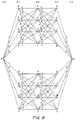
- Fig. 8 shows a trellis that is a complete graphical representation of the decoding procedure appropriate for a BCM scheme employing three component codes C 0 (rate 1/4 repetition code), C 1 (rate 3/4 single-parity-check code), and C 2 (rate 3/4 single-parity-check code) whose bits are mapped onto the constellation of eight 8-PSK symbols.
- C 0 rate 1/4 repetition code
- C 1 rate 3/4 single-parity-check code
- C 2 rate 3/4 single-parity-check code
- each code symbol is mapped onto a constellation of modulation symbols, thereby generating a stream of modulation symbols wherein the modulation symbols are assigned locations in the constellation based on maximized products of non-zero squared Euclidean distances between code symbols along decoding trellis paths.
- Each possible BCM codeword corresponds to a respective path through the trellis.
- the BCM component codes each have a block length of four, yielding four triplets of coded bits (addressing four 8-PSK symbols) for each BCM codeword that represents seven information bits.
- each path through the trellis comprises a set of branches, e.g., AB, BC, CD, and DO.
- Each branch is labeled with the decimal value of a respective triplet ⁇ b 2 b 1 b 0 ⁇ that can be generated by the three component-code encoders at each signalling interval.
- the branches AB, BC, CD, and DO are labeled with the values 0, 0, 0, and 0, respectively.
- the path ABCDO represents the BCM codeword comprising all zeroes.
- the path AXPZO represents the BCM codeword comprising all sevens.
- Decoding such a BCM codeword is preferably done using the well known Viterbi algorithm, which has also been modeled as a trellis.
- each branch of the trellis represents a symbol and a metric is assigned to each branch that corresponds to the likelihood that the symbol represented by that branch is the actual transmitted symbol.
- One such metric is the squared Euclidean distance between a received signal and an estimated value of the signal, using the hypothesis that the symbol corresponding to that branch was actually transmitted.
- Branches merge at each node in the trellis, and at each node the branch assigned the lowest valued metric is selected and used to update a node metric, or path metric. This is repeated through the trellis, and finally the path having the best path metric is selected.
- the information bits that are represented by the symbols represented by the selected path are produced as the decoded bits.
- a (4,1) repetition code is the inner code and a (4,3) single-parity-check code is the outer code.
- the symbol interleaver 17 at the transmitter is configured as an array of memory elements having four columns and sixty-eight rows, and the four modulation symbols comprising each BCM codeword are written into the interleaver 17 by row and read out by column. Hence, successive symbols in a BCM codeword are separated by sixty-eight symbol periods, which provides protection in a fading environment.
- the receiver includes a de-interleaver 32 for recreating the picture at the transmitter.
- the de-interleaver 32 also is configured as an array of memory elements having four columns and sixty-eight rows.
- the received symbols produced by the sample timing selector 31 are written into the de-interleaver 32 by row, and thus each row stores a BCM codeword comprising successive symbols that have been affected by radio propagation conditions that were separated in time by sixty-eight symbol durations.
- Each row of symbols stored in the de-interleaver 32 is decoded by an improved decoder 33' using the Viterbi algorithm as described above. Since the inner code is a repetition code that produces the same bits over the entire block length (trellis), only two path metrics at the end of each decoded row of the de-interleaver array need be retained. These two path metrics are soft information that is used during the decoding of the outer code.
- the decoding of the stream b 0 encoded according to the product code is described below.
- the bits b 0 are protected by the product code, comprising the inner code and the outer code as illustrated in Fig. 5a.
- a value of 1 may be decoded if the best path, i.e., the path having the best path metric, is in the bottom half of the trellis shown in Fig. 8, and a value of 0 may be decoded if the best path is in the top half of the trellis. This can be decided from Fig. 9.
- Rules 1 and 2 above show how one can use the soft information (for each bit of the codeword of the outer code) to make a decision on the codeword of the outer code. Thus, the rules 1 and 2 are applicable in all cases.
- This method can be generalized: Through the decoding process of the inner (BCM) codeword, one can generate soft information (metrics) related to the bits of the outer codeword. This soft information can then be used to decode the outer codeword. Then, using the decoded bits of the outer codeword, the remaining bits of the inner codeword can be decoded.
- metrics soft information
- N block 4, and the (4,3) single-parity-check code has eight possible codewords, which are the code-symbol quadruplets ⁇ 0000 ⁇ , ⁇ 0011 ⁇ , ⁇ 0101 ⁇ , ⁇ 0110 ⁇ , ⁇ 1001 ⁇ , ⁇ 1010 ⁇ , ⁇ 1100 ⁇ , and ⁇ 1111 ⁇ .
- the codeword that is optimal according to Rules 1 or 2 is chosen, and its bits are produced by the BCM decoder as the corresponding data bits i 0 . This completes the decoding of the bit stream b 0 over the inner and outer codes.
- the bits from the codeword of the outer code are in consecutive rows (j, j+1, j+2, ... , j+N block -1), as illustrated by outer codeword 901. If there is an interleaver, then the bits from the codeword of the outer code are in rows (j 1 , j 2 , ..., j N_block ), where the j k 's are not consecutive, as illustrated by outer codeword 903. In this latter case, the particular j k 's for each codeword of the outer code are determined by the additional interleaver 17-1, and cannot be specified by any universally applicable formula.
- the decoding process for the embodiment that includes the additional interleaver 17-1 is substantially as outlined above, with the exception that path metrics P 0j and P 1j from appropriate rows are combined according to Rules 1 or 2 to decode the bits.
- the additional interleaver 17-1 yielding the arrangement that generates, for example, the outer codeword 903 is a rectangular interleaver having seventeen rows and four columns. This separates successive bits of the outer code by seventeen symbol periods.
- the inner-code bits are interleaved as described above by a block interleaver 17 having sixty-eight rows and four columns.
- the use of a product code as described above can be utilized to improve the decoding of the remaining bits in each symbol. This is because once the product-coded bits have been decoded, knowledge of what its constituent bits are can be used to make better decisions in the decoding of the remaining coded bits produced by the other codes. For example, referring back to Fig. 9, the decoding of codeword 0 has been described: one first generates soft information for rows 1 through 4; then, the soft information for bits b 0 1 , b 0 5 , b 0 9 and b 0 13 are used to perform the outer decoding. Once this has been decoded, however, one has better information about the values of these particular bits.
- a product code is used to improve the performance of a class of bits in a coded modulation scheme without increasing the decoding complexity or decreasing the BER performance of the other classes of bits.
- the decoding procedure for the product code uses soft information that is passed between the decoders of the inner and outer codes of the product code. Using a product code provides a significant performance gain for that class of bits at the expense of a marginal reduction in the information rate.
Claims (16)
- Procédé de modulation à codage, comprenant les étapes :de codage de chacun d'une pluralité de flux de bits de données selon un code respectif, en engendrant ainsi des flux respectifs de bits codés, dans lequel un flux de bits de données est codé selon un code-produit et au moins un autre flux de bits de données est codé selon au moins un autre code ; etde choix de symboles de modulation basés sur des groupes respectifs de bits codés, dans lequel chaque groupe comprend des bits codés provenant de tous les flux de bits codés ;ledit procédé étant caractérisé en ce qu'un code interne du code-produit et l'au moins un autre code sont des codes à blocs, et dans lequel en outre les codes à blocs ont une même longueur prédéterminée de bloc.
- Procédé selon la revendication 1, dans lequel l'étape de codage comprend les étapes de codage du flux de bits de données selon un code externe, en engendrant ainsi un flux de bits de code externe et de codage du flux de bits de code externe selon le code interne, en engendrant ainsi un flux de bits de code-produit, et dans lequel le code interne a la longueur prédéterminée de bloc.
- Procédé selon la revendication 2, comprenant en outre l'étape d'imbrication des bits de code externe, dans lequel les bits imbriqués de code externe sont codés selon le code interne afin d'engendrer les bits de code-produit.
- Procédé selon la revendication 1, dans lequel les symboles de modulation sont des symboles de modulation par déplacement de phase.
- Modulateur à codage, comprenant :un moyen (15') de codage de chacun d'une pluralité de flux (i0, i1, i2) de bits de données selon un code respectif et de production de flux respectifs de bits codés (b0, b1, b2), dans lequel au moins un des flux de bits (i0, i1, i2) de données est codé selon un code-produit (15-1, 15-2) etdans lequel les flux restants de bits de données sont codés selon au moins un autre code (c1, c2); et
un moyen (16) de choix de symboles de modulation basés sur des groupes respectifs des bits codés (b0, b1, b2), dans lequel chaque groupe comprend des bits codés provenant de tous les flux de bits de données, ledit modulateur étant caractérisé en ce qu'un code interne (15-2) du code-produit et l'au moins un autre code (c1, c2) sont des codes à blocs, et dans lequel en outre les codes à blocs (15-2, c1, c2) ont une même longueur prédéterminée de bloc. - Modulateur à codage selon la revendication 5, dans lequel le moyen de codage comprend un moyen destiné à coder un flux de bits de données selon un code externe (15-1), en engendrant ainsi un flux de bits de code externe, et un moyen destiné à coder le flux de bits de code externe selon un code interne (15-2), en engendrant ainsi le flux de bits de code-produit, et dans lequel le code interne a la longueur prédéterminée de bloc.
- Modulateur à codage selon la revendication 6, dans lequel le moyen de codage comprend en outre un moyen (17-1) destiné à imbriquer les bits de code externe en engendrant ainsi des bits imbriqués de code externe, et dans lequel les bits imbriqués de code externe sont codés selon le code interne.
- Modulateur à codage selon la revendication 5, dans lequel le moyen de choix comprend une mémoire comportant une pluralité d'emplacements de mémorisation qui sont identifiés par des adresses respectives, dans lequel chaque symbole de modulation est mémorisé dans l'un, respectif, des emplacements de mémorisation, et dans lequel le moyen de choix récupère les symboles de modulation mémorisés dans des emplacements de mémorisation identifiés par les groupes de bits codés.
- Appareil de communication, comprenant :un moyen (12) destiné à engendrer plusieurs flux de bits de données, comprenant un premier flux de bits (i0) de données et d'autres flux de bits (i1, i0) de données ;un premier moyen destiné à coder le premier flux de bits (i0) de données selon un code-produit (15-1, 15-2) et à engendrer un flux de bits (b0) de code-produit ;au moins un second moyen (c1, c2) destiné à coder les autres flux de bits (i1, i2) de données selon au moins un autre code et à engendrer au moins un flux de bits (b1, b2) d'autre code ;un moyen (16) destiné à choisir un symbole de modulation basé sur des groupes respectifs des bits (b0) de code-produit et des bits (b1, b2) d'autre code, dans lequel chaque groupe comprend au moins un bit (b0) de code-produit et au moins un bit (b1, b2) d'autre code, ledit appareil étant caractérisé en ce que le code interne du code-produit et l'au moins un autre code sont des codes à blocs, et dans lequel en outre les codes à blocs ont la même longueur prédéterminée de bloc ;un moyen (17) destiné à imbriquer les symboles choisis de modulation ;un moyen (21, 22, 23) destiné à émettre un signal de porteuse modulé par les symboles imbriqués choisis de modulation ;un moyen (25, 26, 27) destiné à recevoir le signal de porteuse modulé par les symboles imbriqués choisis de modulation et à récupérer (29, 30, 31) les symboles imbriqués de modulation choisis ;un moyen (32) destiné à désimbriquer les symboles imbriqués choisis de modulation ; etun moyen (33) destiné à décoder les symboles désimbriqués choisis de modulation, en récupérant ainsi la pluralité de flux de bits (i0, i1, i2) de données ;dans lequel le moyen (32) de désimbrication comprend une mémoire comportant un groupement d'emplacements de mémorisation qui sont identifiés par des adresses respectives, dans lequel les symboles imbriqués choisis de modulation sont mémorisés dans des emplacements respectifs de mémorisation, et dans lequel le moyen de décodage décode les symboles de modulation mémorisés dans la mémoire selon un algorithme de Viterbi ; et
dans lequel les symboles de modulation sont mémorisés dans la mémoire de façon que tous les bits codés produits par le code interne soient mémorisés dans des rangées respectives, et dans lequel le moyen de décodage, en décodant les bits codés mémorisés dans chaque rangée, engendre de l'information logicielle représentant un mot de code entier de modulation à codage à blocs qui est utilisé pour le décodage des bits codés produits par le code externe. - Appareil de communication selon la revendication 9, dans lequel le premier moyen comprend un moyen externe (15-1) destiné à coder le flux de bits de données selon un code externe, en engendrant ainsi un flux de bits (i0) de code externe, un moyen interne (15-2) destiné à coder le flux de bits (i0) de code externe selon un code interne, en engendrant ainsi le flux de bits (b0) de code-produit.
- Appareil de communication selon la revendication 10, dans lequel le code externe, le code interne, et l'au moins un autre code sont des codes à blocs.
- Appareil de communication selon la revendication 10, dans lequel le premier moyen comprend en outre un moyen (17-1) destiné à désimbriquer les bits de code externe engendrés par le moyen externe (15-1), et dans lequel le moyen interne (15-2) code les bits imbriqués de code externe.
- Appareil de communication selon la revendication 9, dans lequel le moyen (33) de décodage utilise un processus itératif de décodage dans lequel de l'information logicielle est engendrée par décodage des bits codés mémorisés dans chaque rangée, dans lequel l'information logicielle est utilisée au décodage des bits codés produits par le code externe, et dans lequel les bits décodés produits par le code externe sont utilisés pour décoder à nouveau les bits codés mémorisés dans chaque rangée.
- Appareil (33') destiné à décoder un flux de symboles de modulation qui représentent respectivement des bits codés, dans lequel les bits codés sont produits par des codes respectifs et dans lequel au moins un des codes respectifs est un code-produit incluant au moins un code interne et au moins un code externe, ledit appareil étant caractérisé en ce que chacun de l'au moins un code interne est un code à blocs, dans lequel ceux qui restent des codes respectifs sont des codes à blocs, et dans lequel tous les codes à blocs ont une même longueur prédéterminée de bloc, l'appareil comprenant :une mémoire comportant un groupement d'emplacements de mémorisation qui sont identifiés par des adresses respectives ;un moyen destiné à mémoriser les symboles de modulation dans des emplacements respectifs de mémorisation ; etun moyen destiné à décoder les symboles de modulation mémorisés dans la mémoire selon un algorithme de Viterbi ;dans lequel les symboles de modulation sont mémorisés dans la mémoire de façon que tous les bits codés produits par l'au moins un code interne soient mémorisés dans des rangées respectives, et dans lequel le moyen de décodage, en décodant les bits codés mémorisés dans chaque rangée, engendre de l'information logicielle qui représente un mot de code entier de modulation à codage à blocs qui est utilisé au décodage des bits codés produits par le code externe.
- Appareil selon la revendication 14, dans lequel le moyen de décodage utilise un processus itératif de décodage dans lequel de l'information logicielle est engendrée par décodage des bits codés mémorisés dans chaque rangée, dans lequel l'information logicielle est utilisée au décodage des bits codés produits par l'au moins un code externe, et dans lequel les bits de code décodés produits par l'au moins un code externe sont utilisés pour décoder à nouveau les bits codés mémorisés dans chaque rangée.
- Appareil selon la revendication 14, dans lequel les bits codés produits par l'au moins un code externe sont mémorisés dans des rangées non adjacentes de la mémoire.
Applications Claiming Priority (3)
| Application Number | Priority Date | Filing Date | Title |
|---|---|---|---|
| US938516 | 1986-12-05 | ||
| US08/938,516 US6031874A (en) | 1997-09-26 | 1997-09-26 | Unequal error protection in coded modulation schemes |
| PCT/US1998/019884 WO1999017487A1 (fr) | 1997-09-26 | 1998-09-25 | Protection inegale contre les erreurs dans des schemas de modulation codes |
Publications (2)
| Publication Number | Publication Date |
|---|---|
| EP1018232A1 EP1018232A1 (fr) | 2000-07-12 |
| EP1018232B1 true EP1018232B1 (fr) | 2006-06-28 |
Family
ID=25471546
Family Applications (1)
| Application Number | Title | Priority Date | Filing Date |
|---|---|---|---|
| EP98949438A Expired - Lifetime EP1018232B1 (fr) | 1997-09-26 | 1998-09-25 | Protection inegale contre les erreurs dans des schemas de modulation codes |
Country Status (6)
| Country | Link |
|---|---|
| US (1) | US6031874A (fr) |
| EP (1) | EP1018232B1 (fr) |
| CN (1) | CN1184768C (fr) |
| AU (1) | AU9576098A (fr) |
| DE (1) | DE69835096D1 (fr) |
| WO (1) | WO1999017487A1 (fr) |
Families Citing this family (70)
| Publication number | Priority date | Publication date | Assignee | Title |
|---|---|---|---|---|
| US6279132B1 (en) * | 1998-09-28 | 2001-08-21 | Trw Inc. | Concatenated error control method and system for a processing satellite uplink |
| EP0998045A1 (fr) * | 1998-10-30 | 2000-05-03 | Lucent Technologies Inc. | Méthode et système de transmission numérique |
| EP0998087A1 (fr) * | 1998-10-30 | 2000-05-03 | Lucent Technologies Inc. | Système et procédé de transmission à niveaux multiples avec mappage adaptatif |
| DE19857677B4 (de) * | 1998-12-14 | 2008-04-24 | Siemens Ag | Verfahren und Anordnung zur Kodierung von Symbolen für eine Übertragung über eine Funkschnittstelle eines Funk-Kommunikationssystems |
| US6430401B1 (en) * | 1999-03-29 | 2002-08-06 | Lucent Technologies Inc. | Technique for effectively communicating multiple digital representations of a signal |
| US6351832B1 (en) | 1999-05-28 | 2002-02-26 | Lucent Technologies Inc. | Turbo code symbol interleaver |
| US6643332B1 (en) * | 1999-07-09 | 2003-11-04 | Lsi Logic Corporation | Method and apparatus for multi-level coding of digital signals |
| US7089477B1 (en) * | 1999-08-18 | 2006-08-08 | California Institute Of Technology | Interleaved serial concatenation forming turbo-like codes |
| US6466569B1 (en) * | 1999-09-29 | 2002-10-15 | Trw Inc. | Uplink transmission and reception techniques for a processing satelliteation satellite |
| US7116710B1 (en) | 2000-05-18 | 2006-10-03 | California Institute Of Technology | Serial concatenation of interleaved convolutional codes forming turbo-like codes |
| US7159164B1 (en) * | 2000-06-05 | 2007-01-02 | Qualcomm Incorporated | Method and apparatus for recovery of particular bits of a frame |
| DE10057282C2 (de) * | 2000-11-17 | 2003-12-04 | Bosch Gmbh Robert | Verfahren zur codierten Modulation |
| US7173551B2 (en) * | 2000-12-21 | 2007-02-06 | Quellan, Inc. | Increasing data throughput in optical fiber transmission systems |
| IL156586A0 (en) * | 2001-03-29 | 2004-01-04 | Quellan Inc | Increasing data throughput in optical fiber transmission systems |
| US7149256B2 (en) * | 2001-03-29 | 2006-12-12 | Quellan, Inc. | Multilevel pulse position modulation for efficient fiber optic communication |
| US7307569B2 (en) * | 2001-03-29 | 2007-12-11 | Quellan, Inc. | Increasing data throughput in optical fiber transmission systems |
| EP1384338B1 (fr) * | 2001-04-04 | 2010-12-15 | Quellan, Inc. | Procede et systeme permettant de decoder des signaux multiniveau |
| US6973611B2 (en) * | 2001-04-17 | 2005-12-06 | Texas Instruments Incorporated | Interleaved coder and method |
| US20030030873A1 (en) * | 2001-05-09 | 2003-02-13 | Quellan, Inc. | High-speed adjustable multilevel light modulation |
| FR2826208B1 (fr) * | 2001-06-19 | 2003-12-05 | Thales Sa | Systeme et procede de transmission d'un signal audio ou phonie |
| US6990624B2 (en) * | 2001-10-12 | 2006-01-24 | Agere Systems Inc. | High speed syndrome-based FEC encoder and decoder and system using same |
| US7212580B2 (en) * | 2002-02-15 | 2007-05-01 | Quellan, Inc. | Multi-level signal clock recovery technique |
| US6934679B2 (en) * | 2002-03-07 | 2005-08-23 | Microsoft Corporation | Error resilient scalable audio coding |
| US7283966B2 (en) * | 2002-03-07 | 2007-10-16 | Microsoft Corporation | Scalable audio communications utilizing rate-distortion based end-to-end bit allocation |
| WO2003077423A2 (fr) * | 2002-03-08 | 2003-09-18 | Quellan, Inc. | Convertisseur analogique-numerique a grande vitesse faisant intervenir un code gray unique |
| US6801580B2 (en) * | 2002-04-09 | 2004-10-05 | Qualcomm, Incorporated | Ordered successive interference cancellation receiver processing for multipath channels |
| US7158539B2 (en) * | 2002-04-16 | 2007-01-02 | Microsoft Corporation | Error resilient windows media audio coding |
| US20030198478A1 (en) * | 2002-04-23 | 2003-10-23 | Quellan, Inc. | Method and system for generating and decoding a bandwidth efficient multi-level signal |
| JP2004013681A (ja) * | 2002-06-10 | 2004-01-15 | Bosu & K Consulting Kk | 名刺情報管理システム |
| US7020829B2 (en) * | 2002-07-03 | 2006-03-28 | Hughes Electronics Corporation | Method and system for decoding low density parity check (LDPC) codes |
| US7577207B2 (en) * | 2002-07-03 | 2009-08-18 | Dtvg Licensing, Inc. | Bit labeling for amplitude phase shift constellation used with low density parity check (LDPC) codes |
| US7035361B2 (en) * | 2002-07-15 | 2006-04-25 | Quellan, Inc. | Adaptive noise filtering and equalization for optimal high speed multilevel signal decoding |
| US20040019845A1 (en) * | 2002-07-26 | 2004-01-29 | Hughes Electronics | Method and system for generating low density parity check codes |
| US7864869B2 (en) | 2002-07-26 | 2011-01-04 | Dtvg Licensing, Inc. | Satellite communication system utilizing low density parity check codes |
| US7934144B2 (en) | 2002-11-12 | 2011-04-26 | Quellan, Inc. | High-speed analog-to-digital conversion with improved robustness to timing uncertainty |
| KR100511299B1 (ko) * | 2002-12-13 | 2005-08-31 | 엘지전자 주식회사 | 이동 통신 시스템의 데이터 심볼 맵핑 및 확산 장치 |
| US7804760B2 (en) * | 2003-08-07 | 2010-09-28 | Quellan, Inc. | Method and system for signal emulation |
| GB2421674B (en) * | 2003-08-07 | 2006-11-15 | Quellan Inc | Method and system for crosstalk cancellation |
| US7613985B2 (en) * | 2003-10-24 | 2009-11-03 | Ikanos Communications, Inc. | Hierarchical trellis coded modulation |
| DE602004030032D1 (de) * | 2003-11-17 | 2010-12-23 | Quellan Inc | Verfahren und system zur löschung von antennenstörungen |
| US7616700B2 (en) * | 2003-12-22 | 2009-11-10 | Quellan, Inc. | Method and system for slicing a communication signal |
| US20050180332A1 (en) * | 2004-02-13 | 2005-08-18 | Broadcom Corporation | Low latency interleaving and deinterleaving |
| US7673213B2 (en) * | 2004-02-19 | 2010-03-02 | Trellisware Technologies, Inc. | Method and apparatus for communications using improved turbo like codes |
| US7958425B2 (en) * | 2004-02-19 | 2011-06-07 | Trelliware Technologies, Inc. | Method and apparatus for communications using turbo like codes |
| US8209579B2 (en) * | 2004-03-31 | 2012-06-26 | Intel Corporation | Generalized multi-threshold decoder for low-density parity check codes |
| GB2414638A (en) * | 2004-05-26 | 2005-11-30 | Tandberg Television Asa | Decoding a concatenated convolutional-encoded and block encoded signal |
| US8089855B2 (en) * | 2004-06-04 | 2012-01-03 | Qualcomm Incorporated | Transmission of overhead information for broadcast and multicast services in a wireless communication system |
| CN101341659B (zh) * | 2004-08-13 | 2012-12-12 | Dtvg许可公司 | 用于多输入多输出通道的低密度奇偶校验码的码设计与实现的改进 |
| CN100411476C (zh) * | 2004-09-20 | 2008-08-13 | 华为技术有限公司 | 一种宽带码分多址系统中上行增强链路信令编码方法 |
| US7725079B2 (en) * | 2004-12-14 | 2010-05-25 | Quellan, Inc. | Method and system for automatic control in an interference cancellation device |
| US7522883B2 (en) * | 2004-12-14 | 2009-04-21 | Quellan, Inc. | Method and system for reducing signal interference |
| US8015468B2 (en) * | 2004-12-29 | 2011-09-06 | Intel Corporation | Channel estimation and fixed thresholds for multi-threshold decoding of low-density parity check codes |
| CN101091319B (zh) * | 2004-12-29 | 2013-01-02 | 英特尔公司 | 多级低密度奇偶校验 |
| CN101133558B (zh) * | 2005-02-03 | 2010-10-06 | 新加坡科技研究局 | 发射数据的方法、接收数据的方法、发射器和接收器 |
| US7856584B2 (en) * | 2005-03-30 | 2010-12-21 | Intel Corporation | Unequal error protection apparatus, systems, and methods |
| US7987415B2 (en) * | 2006-02-15 | 2011-07-26 | Samsung Electronics Co., Ltd. | Method and system for application of unequal error protection to uncompressed video for transmission over wireless channels |
| US9252983B2 (en) * | 2006-04-26 | 2016-02-02 | Intersil Americas LLC | Method and system for reducing radiated emissions from a communications channel |
| US7958426B2 (en) * | 2006-08-25 | 2011-06-07 | Innovation Specialists, Llc | Distributed block coding (DBC) |
| US9706599B1 (en) | 2009-07-23 | 2017-07-11 | Marvell International Ltd. | Long wireless local area network (WLAN) packets with midambles |
| CN104702376B (zh) * | 2009-07-29 | 2018-04-13 | 马维尔国际贸易有限公司 | 用于wlan发送的方法和装置 |
| US8792469B2 (en) * | 2009-10-02 | 2014-07-29 | Sharp Laboratories Of America, Inc. | Coding a control message with determined data code block repetition |
| US8416734B2 (en) * | 2010-08-02 | 2013-04-09 | Research In Motion Limited | System and method for joint voice and data transmission |
| US9047203B1 (en) * | 2011-12-21 | 2015-06-02 | Altera Corporation | Systems and methods for encoding and decoding data |
| FR2997249B1 (fr) * | 2012-10-19 | 2016-01-29 | Commissariat Energie Atomique | Methode de codage pour canal a evanouissement quasi-periodique |
| US9832059B2 (en) | 2014-06-02 | 2017-11-28 | Marvell World Trade Ltd. | High efficiency orthogonal frequency division multiplexing (OFDM) physical layer (PHY) |
| EP3155779B1 (fr) | 2014-06-11 | 2019-10-16 | Marvell World Trade Ltd. | Preambule comprime pour un systeme de communication sans fil |
| KR102205614B1 (ko) * | 2014-09-19 | 2021-01-21 | 삼성전자주식회사 | 반복 복호를 사용하는 비트 인터리빙 부호화 변조 방식을 지원하는 통신 시스템에서 신호 송/수신 장치 및 방법 |
| CN107196733B (zh) | 2016-03-14 | 2020-11-06 | 华为技术有限公司 | 一种调制方法和装置 |
| CN110710176B (zh) | 2017-06-09 | 2022-12-02 | 马维尔亚洲私人有限公司 | 带有具有压缩ofdm符号的中间码的分组 |
| US10715365B2 (en) | 2017-09-22 | 2020-07-14 | Nxp Usa, Inc. | Determining number of midambles in a packet |
Family Cites Families (24)
| Publication number | Priority date | Publication date | Assignee | Title |
|---|---|---|---|---|
| US4304962A (en) * | 1965-08-25 | 1981-12-08 | Bell Telephone Laboratories, Incorporated | Data scrambler |
| US3810021A (en) * | 1972-06-16 | 1974-05-07 | Bell Telephone Labor Inc | Inband generation of digital signaling waveforms |
| US4015222A (en) * | 1975-12-01 | 1977-03-29 | Bell Telephone Laboratories, Incorporated | Modulated passband signal generator |
| US4170764A (en) * | 1978-03-06 | 1979-10-09 | Bell Telephone Laboratories, Incorporated | Amplitude and frequency modulation system |
| US4247940A (en) * | 1979-10-15 | 1981-01-27 | Bell Telephone Laboratories, Incorporated | Equalizer for complex data signals |
| US4457004A (en) * | 1982-02-08 | 1984-06-26 | Bell Telephone Laboratories, Incorporated | Multidimensional channel coding |
| US4597090A (en) * | 1983-04-14 | 1986-06-24 | Codex Corporation | Block coded modulation system |
| US4489418A (en) * | 1983-04-18 | 1984-12-18 | At&T Bell Laboratories | Differential encoding technique |
| US4520490A (en) * | 1983-08-05 | 1985-05-28 | At&T Information Systems Inc. | Differentially nonlinear convolutional channel coding with expanded set of signalling alphabets |
| US4802171A (en) * | 1987-06-04 | 1989-01-31 | Motorola, Inc. | Method for error correction in digitally encoded speech |
| US5168509A (en) * | 1989-04-12 | 1992-12-01 | Kabushiki Kaisha Toshiba | Quadrature amplitude modulation communication system with transparent error correction |
| US5029185A (en) * | 1989-07-28 | 1991-07-02 | At&T Bell Laboratories | Coded modulation for mobile radio |
| US5371750A (en) * | 1990-03-02 | 1994-12-06 | Mitsubishi Denki Kabushiki Kaisha | Error-correction encoding and decoding system |
| US5105442A (en) * | 1990-11-07 | 1992-04-14 | At&T Bell Laboratories | Coded modulation with unequal error protection |
| US5164963A (en) * | 1990-11-07 | 1992-11-17 | At&T Bell Laboratories | Coding for digital transmission |
| US5214656A (en) * | 1990-12-13 | 1993-05-25 | At&T Bell Laboratories | Multiplexed coded modulation with unequal error protection |
| US5349589A (en) * | 1991-07-01 | 1994-09-20 | Ericsson Ge Mobile Communications Inc. | Generalized viterbi algorithm with tail-biting |
| US5416804A (en) * | 1991-08-21 | 1995-05-16 | U.S. Philips Corporation | Digital signal decoder using concatenated codes |
| US5289501A (en) * | 1991-11-26 | 1994-02-22 | At&T Bell Laboratories | Coded modulation with unequal error protection for fading channels |
| US5519734A (en) * | 1994-08-15 | 1996-05-21 | Lsi Logic Corporation | Synchronization arrangement for decoder-de-interleaver |
| US5724385A (en) * | 1994-09-30 | 1998-03-03 | Qualcomm Incorporated | Serial linked interconnect for summation of multiple waveforms on a common channel |
| US5671156A (en) * | 1995-03-31 | 1997-09-23 | Lucent Technologies Inc. | Transmission method and system for JPEG images |
| US5751702A (en) * | 1995-12-05 | 1998-05-12 | Stanford Telecommunications, Inc. | Network protocol for wireless broadband ISDN using ATM |
| US5734962A (en) * | 1996-07-17 | 1998-03-31 | General Electric Company | Satellite communications system utilizing parallel concatenated coding |
-
1997
- 1997-09-26 US US08/938,516 patent/US6031874A/en not_active Expired - Lifetime
-
1998
- 1998-09-25 CN CNB988115972A patent/CN1184768C/zh not_active Expired - Fee Related
- 1998-09-25 DE DE69835096T patent/DE69835096D1/de not_active Expired - Lifetime
- 1998-09-25 WO PCT/US1998/019884 patent/WO1999017487A1/fr active IP Right Grant
- 1998-09-25 AU AU95760/98A patent/AU9576098A/en not_active Abandoned
- 1998-09-25 EP EP98949438A patent/EP1018232B1/fr not_active Expired - Lifetime
Also Published As
| Publication number | Publication date |
|---|---|
| CN1184768C (zh) | 2005-01-12 |
| US6031874A (en) | 2000-02-29 |
| CN1280725A (zh) | 2001-01-17 |
| WO1999017487A1 (fr) | 1999-04-08 |
| EP1018232A1 (fr) | 2000-07-12 |
| DE69835096D1 (de) | 2006-08-10 |
| AU9576098A (en) | 1999-04-23 |
Similar Documents
| Publication | Publication Date | Title |
|---|---|---|
| EP1018232B1 (fr) | Protection inegale contre les erreurs dans des schemas de modulation codes | |
| KR101435681B1 (ko) | 저밀도 패리티 검사 부호를 사용하는 통신 시스템에서데이터 송수신 장치 및 방법 | |
| US5666370A (en) | High performance error control coding in channel encoders and decoders | |
| US6029264A (en) | System and method for error correcting a received data stream in a concatenated system | |
| KR960016660B1 (ko) | 트렐리스 코드화 큐에이엠(qam)을 이용하여 디지탈 데이터를 통신하기 위한 방법 및 그 장치 | |
| US7292654B2 (en) | Reduced complexity coding system using iterative decoding | |
| US5029185A (en) | Coded modulation for mobile radio | |
| KR100491910B1 (ko) | 비동일 에러 보호를 갖는 통신 신호를 검출하는 방법 및 장치 | |
| US6269129B1 (en) | 64/256 quadrature amplitude modulation trellis coded modulation decoder | |
| JP3269858B2 (ja) | 伝送装置 | |
| US6543023B2 (en) | Parity-check coding for efficient processing of decoder error events in data storage, communication and other systems | |
| US5633881A (en) | Trellis encoder and decoder based upon punctured rate 1/2 convolutional codes | |
| JPH06205054A (ja) | 誤り訂正連接符号化方式 | |
| KR20000068230A (ko) | 정보데이터 다중화 전송시스템과 그 다중화장치 및 분리장치와,에러정정 부호화장치 및 복호장치 | |
| EP0494709B1 (fr) | Système de transmission de signal avec codage en arbre de chacun des paramètres | |
| US8875000B2 (en) | Methods and systems systems for encoding and decoding in trellis coded modulation systems | |
| US20060208930A1 (en) | Encoding method, decoding method, encoding system, recording method, reading method and recording system | |
| JP3634082B2 (ja) | 送信装置および受信装置 | |
| AU723989B2 (en) | Method for decoding data signals using fixed-length decision window | |
| WO2002037693A2 (fr) | Detection fiable d'un champ d'identificateur de format de transport dans un systeme de communications de donnees numeriques | |
| US5920593A (en) | Device for personal digital cellular telephones | |
| EP1432128A2 (fr) | Procédé et dispositif pour démodulation pondéré avec une table de code | |
| US20070109953A1 (en) | Method and apparatus for interleaving \ within a communication system | |
| WO1999017509A1 (fr) | Mises en correspondance de symboles pour modulations codees | |
| US7225392B2 (en) | Error correction trellis coding with periodically inserted known symbols |
Legal Events
| Date | Code | Title | Description |
|---|---|---|---|
| PUAI | Public reference made under article 153(3) epc to a published international application that has entered the european phase |
Free format text: ORIGINAL CODE: 0009012 |
|
| 17P | Request for examination filed |
Effective date: 20000413 |
|
| AK | Designated contracting states |
Kind code of ref document: A1 Designated state(s): DE FR GB |
|
| RAP1 | Party data changed (applicant data changed or rights of an application transferred) |
Owner name: ERICSSON INC. |
|
| 17Q | First examination report despatched |
Effective date: 20040308 |
|
| GRAP | Despatch of communication of intention to grant a patent |
Free format text: ORIGINAL CODE: EPIDOSNIGR1 |
|
| GRAS | Grant fee paid |
Free format text: ORIGINAL CODE: EPIDOSNIGR3 |
|
| GRAA | (expected) grant |
Free format text: ORIGINAL CODE: 0009210 |
|
| AK | Designated contracting states |
Kind code of ref document: B1 Designated state(s): DE FR GB |
|
| REG | Reference to a national code |
Ref country code: GB Ref legal event code: FG4D |
|
| REF | Corresponds to: |
Ref document number: 69835096 Country of ref document: DE Date of ref document: 20060810 Kind code of ref document: P |
|
| PG25 | Lapsed in a contracting state [announced via postgrant information from national office to epo] |
Ref country code: DE Free format text: LAPSE BECAUSE OF FAILURE TO SUBMIT A TRANSLATION OF THE DESCRIPTION OR TO PAY THE FEE WITHIN THE PRESCRIBED TIME-LIMIT Effective date: 20060929 |
|
| PGFP | Annual fee paid to national office [announced via postgrant information from national office to epo] |
Ref country code: DE Payment date: 20061031 Year of fee payment: 9 |
|
| ET | Fr: translation filed | ||
| PLBE | No opposition filed within time limit |
Free format text: ORIGINAL CODE: 0009261 |
|
| STAA | Information on the status of an ep patent application or granted ep patent |
Free format text: STATUS: NO OPPOSITION FILED WITHIN TIME LIMIT |
|
| 26N | No opposition filed |
Effective date: 20070329 |
|
| PGFP | Annual fee paid to national office [announced via postgrant information from national office to epo] |
Ref country code: FR Payment date: 20080917 Year of fee payment: 11 |
|
| PGFP | Annual fee paid to national office [announced via postgrant information from national office to epo] |
Ref country code: GB Payment date: 20080929 Year of fee payment: 11 |
|
| GBPC | Gb: european patent ceased through non-payment of renewal fee |
Effective date: 20090925 |
|
| REG | Reference to a national code |
Ref country code: FR Ref legal event code: ST Effective date: 20100531 |
|
| PG25 | Lapsed in a contracting state [announced via postgrant information from national office to epo] |
Ref country code: FR Free format text: LAPSE BECAUSE OF NON-PAYMENT OF DUE FEES Effective date: 20090930 |
|
| PG25 | Lapsed in a contracting state [announced via postgrant information from national office to epo] |
Ref country code: GB Free format text: LAPSE BECAUSE OF NON-PAYMENT OF DUE FEES Effective date: 20090925 |