EP1018028B1 - Ein gerät zur überwachung teilweiser entladungen in einem gerät mit elektrischer hochspannung oder in einer hochspannungsanlage - Google Patents
Ein gerät zur überwachung teilweiser entladungen in einem gerät mit elektrischer hochspannung oder in einer hochspannungsanlage Download PDFInfo
- Publication number
- EP1018028B1 EP1018028B1 EP97909788A EP97909788A EP1018028B1 EP 1018028 B1 EP1018028 B1 EP 1018028B1 EP 97909788 A EP97909788 A EP 97909788A EP 97909788 A EP97909788 A EP 97909788A EP 1018028 B1 EP1018028 B1 EP 1018028B1
- Authority
- EP
- European Patent Office
- Prior art keywords
- current
- test tap
- coil
- capacitive test
- voltage
- Prior art date
- Legal status (The legal status is an assumption and is not a legal conclusion. Google has not performed a legal analysis and makes no representation as to the accuracy of the status listed.)
- Expired - Lifetime
Links
Images


Classifications
-
- G—PHYSICS
- G01—MEASURING; TESTING
- G01R—MEASURING ELECTRIC VARIABLES; MEASURING MAGNETIC VARIABLES
- G01R15/00—Details of measuring arrangements of the types provided for in groups G01R17/00 - G01R29/00, G01R33/00 - G01R33/26 or G01R35/00
- G01R15/14—Adaptations providing voltage or current isolation, e.g. for high-voltage or high-current networks
- G01R15/142—Arrangements for simultaneous measurements of several parameters employing techniques covered by groups G01R15/14 - G01R15/26
-
- G—PHYSICS
- G01—MEASURING; TESTING
- G01R—MEASURING ELECTRIC VARIABLES; MEASURING MAGNETIC VARIABLES
- G01R31/00—Arrangements for testing electric properties; Arrangements for locating electric faults; Arrangements for electrical testing characterised by what is being tested not provided for elsewhere
- G01R31/12—Testing dielectric strength or breakdown voltage ; Testing or monitoring effectiveness or level of insulation, e.g. of a cable or of an apparatus, for example using partial discharge measurements; Electrostatic testing
- G01R31/14—Circuits therefor, e.g. for generating test voltages, sensing circuits
Definitions
- the present invention relates to a device for monitoring partial discharges in such electric high-voltage equipment or high-voltage apparatus, for example a high-voltage transformer, which has a high-voltage bushing with a capacitive test tap.
- the device comprises an inductive current transducer in the form of a measuring coil arranged around the high-voltage bushing, and signal-processing members adapted, for detection of partial discharges, to be supplied with signals from the inductive current transducer and from the capacitive test tap.
- the transformer has a high-voltage bushing with a capacitive test tap, from which a measurement signal is obtained which is a measure of the electric field at the bushing.
- An inductive transducer in the form of a coil system arranged around the bushing, delivers a measurement signal corresponding to the current through the bushing.
- the two measurement signals are supplied to signal-processing members. In these, the signals are multiplied by each other, which makes it possible to distinguish internal discharges from external disturbances or other signals.
- the signal-processing members comprise means for closer analysis of the measurement signals, for example for determining the level of the internal partial discharge and for triggering an alarm signal if the level exceeds a predetermined alarm level.
- the two measurement signals originate from transducers of different types - one capacitive test tap and one inductive measuring coil. Since the signals during the signal processing are multiplied by each other, they must have the same phase occurrence. To achieve this, the input circuits of the signal-processing members for the two measurement signals must be different, and further, individual adjustment of the input stages in dependence on, inter alia, cable length and type of bushing is required.
- the galvanic connection from the capacitive test tap to the signal-processing members further entails a not insignificant risk of the latter being subjected to overvoltages or other disturbances, for example in case of lightning strokes or other disturbances on the network to which the transformer is connected.
- the current from the capacitive test tap must pass back and further through the cable and the contact means which couple the test tap with the signal-processing members, and in the latter through that impedance network in the form of resistors, capacitors and inductors which is included in the matching circuits of the input stages. This involves a not insignificant risk of interruption in the circuit, which in turn entails a risk of damage to the bushing.
- Another object of the invention is to provide a device in which, to make possible a simple and accurate calibration, the sensitivity can be made similar for both internal and external discharges.
- a further object of the invention is to provide a device in which the input stages of the signal-processing members may be designed identical, and in which the need of individual adjustment is eliminated.
- a still further object of the invention is to provide a device which offers greater operating and personal safety and exhibits less sensitivity to disturbance than the prior art device.
- FIG. 1a shows a prior art device, known from the above-mentioned older patent application, for monitoring partial discharges in an electric power transformer.
- the figure schematically shows a transformer 1 with a bushing 2.
- the bushing has a metal pipe 21 which is attached to the casing of the transformer.
- the pipe 21 supports an insulator 22, in which the conductor 24 (see Fig. 1b) of the bushing is arranged and connected to the electrical connection 23 of the bushing.
- the bushing has a conventional capacitive test tap with a connection box 32. From the test tap (in case of a change of the voltage on the conductor of the bushing), a measurement signal is delivered in the form of a current "i".
- a measuring coil 4 is applied, and from this a measurement signal "u" is obtained (in case of a change of the current in the conductor of the bushing).
- the measurement signals are supplied to a signal-processing member SB via cables 35, 41 (e.g. coaxial cables).
- the measuring coil 4 and the signal-processing member SB are suitably designed in the manner described in the above-mentioned patent application.
- the measuring coil is preferably a whole or divided Rogowski coil
- the signal-processing members are suitably adapted (after necessary matching, filtering, amplification, etc.) to multiply the two measurement signals, which makes possible a determination of whether a detected partial discharge originates from inside the transformer or is caused by an external discharge or other external disturbance.
- a signal PDI is obtained which is a measure of the level or intensity of internal partial discharges in the transformer.
- this signal may be supplied to a data-collection system for monitoring the transformer, for example for triggering an alarm if the discharge level exceeds a predetermined limit value, or for analysis of the condition and function of the transformer in dependence on the detected discharges.
- FIG 1b schematically shows a section through the bushing in the device according to Figure 1a.
- the casing of the transformer 1 is shown connected to ground in the figure, and the potential of the transformer casing will hereinafter be designated “ground” although, in certain cases, the transformer may be erected on a potential deviating from ground.
- the transformer Via the conductor 24 of the bushing, the transformer is connected to a network, symbolically shown as an impedance element NI which corresponds to the impedance of the network, as viewed from the transformer.
- the bushing has a schematically shown capacitive test tap with two connection terminals 33 and 34.
- the terminal 33 is coupled to a capacitor layer 31 arranged in the bushing, and the terminal 34 is coupled to the metal pipe 21, that is, to ground potential.
- the two terminals are coupled to the cable 35.
- the measuring coil 4 is only shown schematically in the figure with its connection terminals 42 and 43, to which the cable 41 is coupled.
- the measurement signals "i” and “u” are supplied to matching circuits ADP1 and ADP2 via the cables 35 and 41.
- the matching circuits are part of the input stage of the signal-processing member SB and comprise impedance networks with passive circuit elements in the form of resistors, capacitors and inductance elements for impedance matching of the inputs of the signal-processing member, and possibly also for matching of the levels of the signals to each other.
- the output signals of the matching circuits are forwarded to other circuits (not shown in the figure), included in the signal-processing member, for filtering, amplification, multiplication, etc.
- Figure 1b illustrates the function of the device in the case of an internal partial discharge.
- the discharge is assumed to be caused by a positive current out through the conductor 24.
- One part of the current, "i" is coupled to ground via the capacitive test tap, and another part, “iz", is coupled to ground via the network coupled to the transformer, for example via line capacitances, surge arrestes and load objects.
- the total current caused by the discharge is thus i + iz.
- the current "i” flows both back and forth through the measuring coil - up through the conductor 24 and down through the pipe 21 - and does not give rise to any net current through the coil.
- the only current which the coil measures is thus i z .
- the measurement signal will therefore be dependent on the impedance of the load of the transformer.
- a load is not always connected, and the current sensed by the coil thus becomes low and the sensitivity of detection of the device poor.
- Figure 1c shows the function of the device in the case of an external partial discharge.
- the measuring coil there pass through the measuring coil both the current "it” which flows to ground via the transformer winding W and the current "i" which flows to ground via the capacitive test tap.
- the coil measures the current i + i t .
- the two measuring channels exhibit the same phase characteristic, which requires that, for example, the input stage for the signal from the capacitive test tap modifies this measurement signal such that its characteristic as far as possible becomes the same as the signal from the measuring coil. Further, it has proved that an individual adjustment of at least one input stage is required in connection with installation of the device, which is due, among other things, to variations in cable length and to the type of bushing being used.
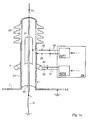
- Figure 2 shows one embodiment of the invention.
- the current-carrying return conductor 36 from the signal-processing member SB is not, as in the previously known device, coupled to the ground terminal 34 of the test tap but instead extended past - outside - the coil 4 to a ground connection 11 on the transformer casing.
- the conductors 24, 35 and 36 thus form a current coil around the coil for discharge signals originating from inside the transformer, which results in these signals in their entirety being detected by the coil.
- the figure shows the case with an internal partial discharge.
- the coil will detect the whole current i + iz.
- the sensitivity to such discharges will thus be good and its dependence on the load impedance of the transformer is considerably reduced.
- For an external discharge on the other hand, only the current i t is detected (cf. Fig. 1c).
- the sensitivity to such discharges, as well as to external disturbances, is thus considerably reduced compared with the known device, which involves an additional advantage.
- the current distribution is made in such a way that one current k ⁇ i flows through the conductor 37 and one current (1-k) ⁇ i through the conductor 36.
- the conductors 36 and 37 are connected together after the passage of the conductor 37 through the measuring coil and the current "i" is thereafter passed via a current-measuring device 6 to the ground connection 11.
- the current-measuring device delivers a measurement signal i', corresponding to the current "i", to the signal-processing member SB.
- the coil measures the current i z + (1-k) ⁇ i and for an external discharge or disturbance, the following current is measured i t + k ⁇ i
- k is chosen such that 0.1 ⁇ k ⁇ 0.5.
- a lower value of k gives higher sensitivity to internal discharges and lower sensitivity to external discharges and disturbances, and is therefore preferable from these points of view.
- it may be advantageous to choose k 0.5, which - if i z and i t are small compared with "i" - gives approximately the same sensitivity to internal and external discharges.
- a power transformer has no ground connection which corresponds to the connection 11 in Figures 2 and 3, and in practice it is mostly difficult or unsuitable to arrange such a connection especially for the monitoring device according to the invention.
- a capacitive test tap normally has two connection terminals, one of which is connected to ground. For practical reasons, therefore, it is often desirable to use this ground terminal for ground connection of the monitoring device.
- Figure 4 Such an embodiment of the device is shown in Figure 4 (also this figure only shows the case of an internal partial discharge).
- the conductor 36 is there extended upwards through the measuring coil and is coupled to the ground terminal 34 of the test tap via the current measuring device 6.
- the function is the same as that described with reference to Figure 3, since the current (1-k) ⁇ i flowing upwards through the coil in the figure gives rise to an equal current flowing downwards through the pipe 21 and thus does not cause any net addition to the total current through the measuring coil.
- Figure 5 shows how the circuits, connected to the capacitive test tap, are designed in a preferred embodiment of the invention, wherein both the current-distributing member 5 and the current-measuring member 6 are constituted by current transformers.
- the current transformer 5 has two windings 51 and 52. With the chosen winding polarities, a current "i" from the test tap will be distributed between the conductors 36 and 37 with the proportion (1-k) i through the conductor 36 and the proportion k ⁇ 1 through the conductor 37.
- the current transformer 6 has two primary windings, 61 and 62, coupled into the current paths 36 and 37.
- the secondary winding 63 of the transformer is coupled to the input stage of the signal-processing membes SB and delivers thereto a measurement signal i' corresponding to the sum of the currents in the conductors 36 and 37, that is, to the current "i".
- the current transformer 6 can be simply designed with the same impedance as the measuring coil.
- the two measurement signals will then have the same frequency and phase characteristic, which means that the two input circuits in the signal-processing members may be designed identical and that the need of individual adjustment during installation is eliminated.
- the signal-processing members through the current transformer are galvanically separated from the bushing, which entails a reduced sensitivity to disturbances and overvoltages.
- An additional advantage is that the capacitive test tap (33) becomes grounded (through the conductors 36, 37 and the current transformers) in a relatively direct and interruption-safe manner, which minimizes the risk of interruptions, which would otherwise damage the bushing.
- a device according to the invention may be used for monitoring partial discharges in other high-voltage equipment or apparatus, for example in gas-insulated switchgear equipment.
- the invention has been described in connection with a certain type of bushing, but it may, of course, be applied to other types of bushings as well.
- the measuring coil which in the examples described is placed between the capacitive test tap and the apparatus (the transformer), may, within the scope of the invention, be alternatively placed on the other side of the test tap (above this in the figures).
- inventions shown in Figures 3 and 4 have current-measuring devices (6), the output signals (i') of which are supplied to the signal-processing members.
- the current "i" of the test tap may also in these embodiments be passed directly to the input stages of the signal-processing members in the manner shown in Figures 1 and 2.
Landscapes
- Physics & Mathematics (AREA)
- General Physics & Mathematics (AREA)
- Testing Relating To Insulation (AREA)
- Emergency Protection Circuit Devices (AREA)
Claims (8)
- Vorrichtung zum Überwachen partieller Entladungen in einer elektrischen Hochspannungseinrichtung oder einer Hochspannungsausrüstung so wie einem Hochspannungs-Wandler bzw. -Transformator (1), wobei die Vorrichtung eine Hochspannungsdurchführung (2) mit einem kapazitiven Prüfanschluss (31-33) aufweist, und wobei die Vorrichtung einen induktiven Strom-Messwandler in der Form einer Messspule (4) umfasst, die um die Hochspannungsbuchse angeordnet ist, ebenso wie signalverarbeitende Elemente (SB), die angepasst sind für die Erfassung von partiellen Entladungen, um mit Messsignalen von dem induktiven Stromgenerator (u) und von dem kapazitiven Prüfanschluss (i, i') versorgt zu werden, wobei die Vorrichtung einen ersten Strompfad (36) aufweist, der mit dem kapazitiven Prüfanschluss verbunden und außerhalb der Spule angeordnet ist, und der angeordnet ist, um zusammen mit dem Leiter (24) der Hochspannungsdurchführung eine Stromschleife um die Spule für Signale zu bilden, die von innerhalb der Einrichtung stammen und aus partiellen Entladungen herrühren.
- Vorrichtung gemäß Anspruch 1, wobei sie einen zweiten Strompfad (37) aufweist, der die Spule durchläuft, ebenso wie stromverteilende Elemente (5), die angepasst sind, einen Strom (i) zu verteilen, der von dem kapazitiven Prüfanschluss zwischen dem ersten (36) und dem zweiten (37) Strompfad fließt.
- Vorrichtung gemäß Anspruch 2, wobei das stromverteilende Element (5) in der Form eines Stromtransformators mit einer ersten Windung (51), die in den ersten Strompfad (36) eingekoppelt ist, und einer zweiten Windung (52), die in den zweiten Strompfad (37) eingekoppelt ist, vorliegt.
- Vorrichtung gemäß irgendeinem der Ansprüche 2 und 3, wobei das stromverteilende Element (5) angepasst ist, den Strom von dem kapazitiven Prüfanschluss zwischen den Strompfaden zu verteilen, so dass ein Strom (1-k) · i durch den ersten Strompfad fließt, und ein Strom k · i durch den zweiten Strompfad fließt, wobei
i der Strom von dem kapazitiven Prüfanschluss ist; und
k eine Konstante in dem Intervall 0,1 ≤ k ≤ 0,5 ist. - Vorrichtung gemäß irgendeinem der vorhergehenden Ansprüche, wobei ein Stromtransformator (6) für die Messung eines Stroms (i) angeordnet ist, der von dem kapazitiven Prüfanschluss fließt, und wobei das Ausgangssignal (i') des Stromtransformators angepasst ist, um den signalverarbeitenden Elementen (SB) zugeführt zu werden.
- Vorrichtung gemäß Anspruch 5, wobei der Stromtransformator (6) so ausgelegt ist, dass er im Vergleich zu den signalverarbeitenden Elementen (SB) im Wesentlichen die gleiche Impedanz zeigt wie die Messspule (4).
- Vorrichtung gemäß irgendeinem der vorhergehenden Ansprüche in einer Einrichtung, deren Hochspannungsdurchführung einen kapazitiven Prüfanschluss mit zwei Verbindungsanschlüssen (33, 34) aufweist, von denen einer (34) eine Masseverbindung darstellt, wobei der Strompfad oder die Strompfade (36, 37), der/die mit dem kapazitiven Prüfanschluss gekoppelt ist/sind, zwischen die zwei Verbindungsanschlüsse (33, 34) des kapazitiven Prüfanschlusses gekoppelt ist/sind.
- Vorrichtung gemäß irgendeinem der vorhergehenden Ansprüche, wobei die Messspule (4) eine Rogowski-Spule ist.
Applications Claiming Priority (3)
| Application Number | Priority Date | Filing Date | Title |
|---|---|---|---|
| SE9603798A SE508154C2 (sv) | 1996-10-16 | 1996-10-16 | Anordning för övervakning av partiella urladdningar i en elektrisk högspänningsapparat eller högspänningsutrustning |
| SE9603798 | 1996-10-16 | ||
| PCT/SE1997/001678 WO1998016841A1 (en) | 1996-10-16 | 1997-10-08 | A device for monitoring partial discharges in an electric high-voltage apparatus or high-voltage equipment |
Publications (2)
| Publication Number | Publication Date |
|---|---|
| EP1018028A1 EP1018028A1 (de) | 2000-07-12 |
| EP1018028B1 true EP1018028B1 (de) | 2004-08-04 |
Family
ID=20404281
Family Applications (1)
| Application Number | Title | Priority Date | Filing Date |
|---|---|---|---|
| EP97909788A Expired - Lifetime EP1018028B1 (de) | 1996-10-16 | 1997-10-08 | Ein gerät zur überwachung teilweiser entladungen in einem gerät mit elektrischer hochspannung oder in einer hochspannungsanlage |
Country Status (6)
| Country | Link |
|---|---|
| EP (1) | EP1018028B1 (de) |
| AT (1) | ATE272847T1 (de) |
| AU (1) | AU4731097A (de) |
| DE (1) | DE69730167T2 (de) |
| SE (1) | SE508154C2 (de) |
| WO (1) | WO1998016841A1 (de) |
Cited By (1)
| Publication number | Priority date | Publication date | Assignee | Title |
|---|---|---|---|---|
| US8163574B2 (en) | 2009-05-08 | 2012-04-24 | Eaton Corporaton | System and method for sensing voltage in medium-to-high voltage applications |
Families Citing this family (9)
| Publication number | Priority date | Publication date | Assignee | Title |
|---|---|---|---|---|
| ES2191557B1 (es) * | 2002-02-15 | 2005-02-01 | Esdras Automatica, S.L. | Transformador para medida de tension y corriente electrica caracterizado por la recepcion de ondas electromagneticas en medio dielectrico. |
| US6968728B2 (en) * | 2003-07-10 | 2005-11-29 | Hydro Quebec | Test tap adapter for extracting dissolved gases from insulating oil and measuring electrical parameters of a transformer bushing |
| US8525523B2 (en) * | 2011-05-03 | 2013-09-03 | General Electric Company | Partial discharge analysis coupling device that generates a pulse signal and a reference signal |
| WO2016052314A1 (ja) * | 2014-09-29 | 2016-04-07 | 三菱電機株式会社 | 絶縁劣化監視装置 |
| CN106353579A (zh) * | 2016-08-30 | 2017-01-25 | 浙江图维科技股份有限公司 | 一种电缆电流、导体温度、内置局放一体化监测装置及方法 |
| EP3312617B1 (de) * | 2016-10-18 | 2019-09-04 | ABB Schweiz AG | Verfahren und vorrichtung zum testen einer galvanischen verbindung einer hochspannungs-kondensator-buchsenanordnung |
| WO2020035494A1 (en) * | 2018-08-15 | 2020-02-20 | Abb Schweiz Ag | Power transformer comprising a turret |
| CN109541412A (zh) * | 2018-12-20 | 2019-03-29 | 国网上海市电力公司 | 基于套管末屏的变压器过电压和局放综合监测系统及方法 |
| AT523525B1 (de) * | 2020-03-31 | 2021-09-15 | Baur Gmbh | Elektrische Schaltungsanordnung |
Family Cites Families (4)
| Publication number | Priority date | Publication date | Assignee | Title |
|---|---|---|---|---|
| DE3601934C2 (de) * | 1986-01-23 | 1995-02-23 | F & G Hochspannungsgeraete Gmb | Permanent überwachte Kondensatordurchführungsanordnung bei Großtransformatoren in Drehstromnetzen |
| DE3764009D1 (de) * | 1986-04-14 | 1990-09-06 | Siemens Ag | Verfahren und vorrichtungen zur erkennung und lokalisierung von schaeden in elektrischen anlagen. |
| JP2884788B2 (ja) * | 1991-02-15 | 1999-04-19 | 富士電機株式会社 | 樹脂モールド変圧器の部分放電測定装置 |
| SE515387C2 (sv) * | 1995-05-02 | 2001-07-23 | Abb Research Ltd | Övervakning av interna partiella urladdningar i en krafttransformator |
-
1996
- 1996-10-16 SE SE9603798A patent/SE508154C2/sv not_active IP Right Cessation
-
1997
- 1997-10-08 DE DE69730167T patent/DE69730167T2/de not_active Expired - Lifetime
- 1997-10-08 AU AU47310/97A patent/AU4731097A/en not_active Abandoned
- 1997-10-08 EP EP97909788A patent/EP1018028B1/de not_active Expired - Lifetime
- 1997-10-08 WO PCT/SE1997/001678 patent/WO1998016841A1/en active IP Right Grant
- 1997-10-08 AT AT97909788T patent/ATE272847T1/de active
Cited By (1)
| Publication number | Priority date | Publication date | Assignee | Title |
|---|---|---|---|---|
| US8163574B2 (en) | 2009-05-08 | 2012-04-24 | Eaton Corporaton | System and method for sensing voltage in medium-to-high voltage applications |
Also Published As
| Publication number | Publication date |
|---|---|
| DE69730167D1 (de) | 2004-09-09 |
| DE69730167T2 (de) | 2005-08-04 |
| ATE272847T1 (de) | 2004-08-15 |
| SE508154C2 (sv) | 1998-09-07 |
| SE9603798D0 (sv) | 1996-10-16 |
| EP1018028A1 (de) | 2000-07-12 |
| AU4731097A (en) | 1998-05-11 |
| WO1998016841A1 (en) | 1998-04-23 |
| SE9603798L (sv) | 1998-04-17 |
Similar Documents
| Publication | Publication Date | Title |
|---|---|---|
| US5933012A (en) | Device for sensing of electric discharges in a test object | |
| EP0544646B1 (de) | Gerät zur Beurteilung des Zustandes einer Isolation | |
| US6433557B1 (en) | Electrical system with capacitance tap and sensor for on-line monitoring the state of high-voltage insulation and remote monitoring device | |
| US5574378A (en) | Insulation monitoring system for insulated high voltage apparatus | |
| EP1102998B1 (de) | Induktiver magnetischer Sensor mit mehreren enggekoppelten Wicklungen | |
| US5652521A (en) | Insulation monitoring system for insulated high voltage apparatus | |
| US6489782B1 (en) | Electrical system with a stand-off insulator-sensor for on-line partial discharge monitoring of the state of high-voltage insulation | |
| EP1295133B1 (de) | Kapazitiver spannungswandler | |
| US5117191A (en) | Apparatus for monitoring degradation of insulation of electrical installation | |
| US10126348B2 (en) | Combined on-line bushing monitoring and geo-magnetic induced current monitoring system | |
| US6504382B2 (en) | Electrical system with a stress shield system for partial discharge on-line monitoring of the state of high-voltage insulation | |
| KR20050007339A (ko) | 고 전류 유도성 커플러 및 전력선용 계기용 변류기 | |
| WO1996018909A9 (en) | Monitoring system for insulated high voltage apparatus | |
| US5854556A (en) | Measurement system for partial discharges on dielectrics in coaxial cables | |
| EP1018028B1 (de) | Ein gerät zur überwachung teilweiser entladungen in einem gerät mit elektrischer hochspannung oder in einer hochspannungsanlage | |
| Van Der Wielen et al. | Sensors for on-line PD detection in MV power cables and their locations in substations | |
| JP2006242725A (ja) | 漏洩電流検出器及び常時監視システム | |
| US4280093A (en) | Zero-current detector for high voltage DC transmission line | |
| JP2007024707A (ja) | クランプメータによる漏れ電流測定、監視装置 | |
| JPH07244111A (ja) | 漏れ電流検出センサ | |
| JP3657064B2 (ja) | 高圧絶縁常時監視装置 | |
| US5055828A (en) | Parasitic-ground current indicator for electrical system | |
| JPH06109800A (ja) | 部分放電監視方法 | |
| JP2753680B2 (ja) | 放電時直列共振回路利用の電気事故予知方法 | |
| CA1157095A (en) | Zero-current detector for high voltage dc transmission line |
Legal Events
| Date | Code | Title | Description |
|---|---|---|---|
| PUAI | Public reference made under article 153(3) epc to a published international application that has entered the european phase |
Free format text: ORIGINAL CODE: 0009012 |
|
| 17P | Request for examination filed |
Effective date: 19990514 |
|
| AK | Designated contracting states |
Kind code of ref document: A1 Designated state(s): AT CH DE ES FR GB IT LI |
|
| GRAP | Despatch of communication of intention to grant a patent |
Free format text: ORIGINAL CODE: EPIDOSNIGR1 |
|
| GRAS | Grant fee paid |
Free format text: ORIGINAL CODE: EPIDOSNIGR3 |
|
| GRAA | (expected) grant |
Free format text: ORIGINAL CODE: 0009210 |
|
| AK | Designated contracting states |
Kind code of ref document: B1 Designated state(s): AT CH DE ES FR GB IT LI |
|
| PG25 | Lapsed in a contracting state [announced via postgrant information from national office to epo] |
Ref country code: LI Free format text: LAPSE BECAUSE OF FAILURE TO SUBMIT A TRANSLATION OF THE DESCRIPTION OR TO PAY THE FEE WITHIN THE PRESCRIBED TIME-LIMIT Effective date: 20040804 Ref country code: IT Free format text: LAPSE BECAUSE OF FAILURE TO SUBMIT A TRANSLATION OF THE DESCRIPTION OR TO PAY THE FEE WITHIN THE PRESCRIBED TIME-LIMIT;WARNING: LAPSES OF ITALIAN PATENTS WITH EFFECTIVE DATE BEFORE 2007 MAY HAVE OCCURRED AT ANY TIME BEFORE 2007. THE CORRECT EFFECTIVE DATE MAY BE DIFFERENT FROM THE ONE RECORDED. Effective date: 20040804 Ref country code: CH Free format text: LAPSE BECAUSE OF FAILURE TO SUBMIT A TRANSLATION OF THE DESCRIPTION OR TO PAY THE FEE WITHIN THE PRESCRIBED TIME-LIMIT Effective date: 20040804 |
|
| REG | Reference to a national code |
Ref country code: GB Ref legal event code: FG4D |
|
| REG | Reference to a national code |
Ref country code: CH Ref legal event code: EP |
|
| REF | Corresponds to: |
Ref document number: 69730167 Country of ref document: DE Date of ref document: 20040909 Kind code of ref document: P |
|
| PG25 | Lapsed in a contracting state [announced via postgrant information from national office to epo] |
Ref country code: ES Free format text: LAPSE BECAUSE OF FAILURE TO SUBMIT A TRANSLATION OF THE DESCRIPTION OR TO PAY THE FEE WITHIN THE PRESCRIBED TIME-LIMIT Effective date: 20041115 |
|
| REG | Reference to a national code |
Ref country code: CH Ref legal event code: PL |
|
| PLBE | No opposition filed within time limit |
Free format text: ORIGINAL CODE: 0009261 |
|
| STAA | Information on the status of an ep patent application or granted ep patent |
Free format text: STATUS: NO OPPOSITION FILED WITHIN TIME LIMIT |
|
| ET | Fr: translation filed | ||
| 26N | No opposition filed |
Effective date: 20050506 |
|
| PGFP | Annual fee paid to national office [announced via postgrant information from national office to epo] |
Ref country code: GB Payment date: 20131002 Year of fee payment: 17 Ref country code: AT Payment date: 20130926 Year of fee payment: 17 Ref country code: FR Payment date: 20131009 Year of fee payment: 17 Ref country code: DE Payment date: 20131002 Year of fee payment: 17 |
|
| REG | Reference to a national code |
Ref country code: DE Ref legal event code: R119 Ref document number: 69730167 Country of ref document: DE |
|
| REG | Reference to a national code |
Ref country code: AT Ref legal event code: MM01 Ref document number: 272847 Country of ref document: AT Kind code of ref document: T Effective date: 20141008 |
|
| GBPC | Gb: european patent ceased through non-payment of renewal fee |
Effective date: 20141008 |
|
| PG25 | Lapsed in a contracting state [announced via postgrant information from national office to epo] |
Ref country code: DE Free format text: LAPSE BECAUSE OF NON-PAYMENT OF DUE FEES Effective date: 20150501 Ref country code: GB Free format text: LAPSE BECAUSE OF NON-PAYMENT OF DUE FEES Effective date: 20141008 |
|
| REG | Reference to a national code |
Ref country code: FR Ref legal event code: ST Effective date: 20150630 |
|
| PG25 | Lapsed in a contracting state [announced via postgrant information from national office to epo] |
Ref country code: FR Free format text: LAPSE BECAUSE OF NON-PAYMENT OF DUE FEES Effective date: 20141031 Ref country code: AT Free format text: LAPSE BECAUSE OF NON-PAYMENT OF DUE FEES Effective date: 20141008 |