EP1018024B1 - Transformateur combine de courant et de tension pour signaux faibles - Google Patents
Transformateur combine de courant et de tension pour signaux faibles Download PDFInfo
- Publication number
- EP1018024B1 EP1018024B1 EP98942445A EP98942445A EP1018024B1 EP 1018024 B1 EP1018024 B1 EP 1018024B1 EP 98942445 A EP98942445 A EP 98942445A EP 98942445 A EP98942445 A EP 98942445A EP 1018024 B1 EP1018024 B1 EP 1018024B1
- Authority
- EP
- European Patent Office
- Prior art keywords
- divider
- voltage
- current
- resistor
- signal current
- Prior art date
- Legal status (The legal status is an assumption and is not a legal conclusion. Google has not performed a legal analysis and makes no representation as to the accuracy of the status listed.)
- Expired - Lifetime
Links
- 238000005259 measurement Methods 0.000 claims description 26
- 230000005693 optoelectronics Effects 0.000 claims description 13
- 239000000919 ceramic Substances 0.000 claims description 9
- 239000012212 insulator Substances 0.000 claims description 9
- 238000012545 processing Methods 0.000 claims description 7
- 239000004033 plastic Substances 0.000 claims description 6
- 229920003023 plastic Polymers 0.000 claims description 6
- 239000000835 fiber Substances 0.000 claims description 5
- 238000012546 transfer Methods 0.000 claims description 5
- 230000003287 optical effect Effects 0.000 claims description 4
- 230000005540 biological transmission Effects 0.000 claims description 3
- 239000003990 capacitor Substances 0.000 claims description 3
- 150000001875 compounds Chemical class 0.000 claims description 3
- 239000011521 glass Substances 0.000 claims description 2
- 230000000712 assembly Effects 0.000 claims 1
- 238000000429 assembly Methods 0.000 claims 1
- 238000005538 encapsulation Methods 0.000 claims 1
- 239000002245 particle Substances 0.000 claims 1
- 238000010079 rubber tapping Methods 0.000 claims 1
- 239000007787 solid Substances 0.000 claims 1
- 230000009466 transformation Effects 0.000 claims 1
- 238000009413 insulation Methods 0.000 description 10
- 239000013307 optical fiber Substances 0.000 description 8
- 239000007789 gas Substances 0.000 description 5
- 239000000463 material Substances 0.000 description 5
- 230000010287 polarization Effects 0.000 description 5
- 239000002184 metal Substances 0.000 description 4
- 229920005989 resin Polymers 0.000 description 4
- 239000011347 resin Substances 0.000 description 4
- 230000001939 inductive effect Effects 0.000 description 3
- 230000001419 dependent effect Effects 0.000 description 2
- 238000013461 design Methods 0.000 description 2
- 230000000694 effects Effects 0.000 description 2
- 238000005516 engineering process Methods 0.000 description 2
- 239000011888 foil Substances 0.000 description 2
- 238000007789 sealing Methods 0.000 description 2
- 238000004804 winding Methods 0.000 description 2
- 238000005266 casting Methods 0.000 description 1
- 230000015556 catabolic process Effects 0.000 description 1
- 238000006243 chemical reaction Methods 0.000 description 1
- 239000004020 conductor Substances 0.000 description 1
- 238000010586 diagram Methods 0.000 description 1
- 238000005553 drilling Methods 0.000 description 1
- 230000005684 electric field Effects 0.000 description 1
- 230000005611 electricity Effects 0.000 description 1
- 239000003822 epoxy resin Substances 0.000 description 1
- 238000011156 evaluation Methods 0.000 description 1
- LNEPOXFFQSENCJ-UHFFFAOYSA-N haloperidol Chemical compound C1CC(O)(C=2C=CC(Cl)=CC=2)CCN1CCCC(=O)C1=CC=C(F)C=C1 LNEPOXFFQSENCJ-UHFFFAOYSA-N 0.000 description 1
- 238000002955 isolation Methods 0.000 description 1
- 238000000691 measurement method Methods 0.000 description 1
- 230000007935 neutral effect Effects 0.000 description 1
- 229920000647 polyepoxide Polymers 0.000 description 1
- 229920001296 polysiloxane Polymers 0.000 description 1
- 229920005749 polyurethane resin Polymers 0.000 description 1
- 229910052573 porcelain Inorganic materials 0.000 description 1
- 238000004382 potting Methods 0.000 description 1
- 238000012360 testing method Methods 0.000 description 1
- 238000012549 training Methods 0.000 description 1
Images
Classifications
-
- G—PHYSICS
- G01—MEASURING; TESTING
- G01R—MEASURING ELECTRIC VARIABLES; MEASURING MAGNETIC VARIABLES
- G01R15/00—Details of measuring arrangements of the types provided for in groups G01R17/00 - G01R29/00, G01R33/00 - G01R33/26 or G01R35/00
- G01R15/04—Voltage dividers
- G01R15/06—Voltage dividers having reactive components, e.g. capacitive transformer
-
- G—PHYSICS
- G01—MEASURING; TESTING
- G01R—MEASURING ELECTRIC VARIABLES; MEASURING MAGNETIC VARIABLES
- G01R15/00—Details of measuring arrangements of the types provided for in groups G01R17/00 - G01R29/00, G01R33/00 - G01R33/26 or G01R35/00
- G01R15/14—Adaptations providing voltage or current isolation, e.g. for high-voltage or high-current networks
- G01R15/142—Arrangements for simultaneous measurements of several parameters employing techniques covered by groups G01R15/14 - G01R15/26
-
- G—PHYSICS
- G01—MEASURING; TESTING
- G01R—MEASURING ELECTRIC VARIABLES; MEASURING MAGNETIC VARIABLES
- G01R1/00—Details of instruments or arrangements of the types included in groups G01R5/00 - G01R13/00 and G01R31/00
- G01R1/02—General constructional details
- G01R1/18—Screening arrangements against electric or magnetic fields, e.g. against earth's field
-
- G—PHYSICS
- G01—MEASURING; TESTING
- G01R—MEASURING ELECTRIC VARIABLES; MEASURING MAGNETIC VARIABLES
- G01R15/00—Details of measuring arrangements of the types provided for in groups G01R17/00 - G01R29/00, G01R33/00 - G01R33/26 or G01R35/00
- G01R15/04—Voltage dividers
Definitions
- the invention relates to a combined small signal current and voltage converter for current and voltage measurement in Outdoor switchgear, as it is in the generic term of the independent Claim 1 is defined.
- the frequency f 0 Hz is therefore excluded for both current and voltage measurement.
- Optoelectronic Current transformers have an optical fiber, through which polarized light is passed. Because of the Faraday effect becomes the plane of polarization of light rotated by the magnetic field generated by the current to be measured. The rotation is proportional to the magnetic field strength and thus to the current strength, so that by measuring the rotation the current level can be determined in the polarization plane can.
- the transport of the measurement signals with optical fibers means that no isolation between the primary current at medium or high voltage potential and the proportional signal at earth potential is necessary.
- the known insulation media for example inelastic insulation resins, oil paper or insulating gases, are also used in the transformer voltage converter, as mentioned above.
- EP-A-0 156 533 there is a combined current and voltage converter disclosed, which consists of an optoelectronic Current transformer and a capacitive voltage divider.
- the current transformer comprises magneto-optical material, in which the polarization plane of fed polarized Light due to the Faraday effect by the from generated magnetic field to be measured is rotated. about a collimator lens turns the rotated light of an evaluation electronics fed.
- the capacitive voltage divider has the disadvantage of being physically unable is, voltages in the frequency range 0 to 5 Hz are sufficiently precise capture.
- DE-A-34 35 418 is a combined current and voltage converter described, in which the current measurement with a Executed shunt and only then by conversion to an optical one Signal is generated.
- the voltage measurement is done with an RC divider, whose secondary tap is at high voltage potential is located, but its structure is not in detail is explained. In particular, it is not clear what kind of resistances be used.
- DE-A-37 14 945 is a frequency-independent RC divider for measuring voltages up to 150 kV in medium and known high-frequency X-ray generators.
- the RC divider has one arranged within the X-ray generator low inductive partial resistance, but its active part due to the very short distance to the high voltage electrode and to the earth electrode and due to the angular meandering shape Flashover exposed to high voltage is and no permanent stability of the gear ratio guaranteed.
- an outside of the X-ray generator arranged partial resistance available that is not explained in detail.
- the described RC divider is not suitable for high and low frequency voltages.
- EP-A-0 510 427 discloses an R-divider that is formed is to be used in an interior of a switchgear be, and therefore not easily with a current transformer can be combined.
- the structure and properties of the in Thick film technology manufactured resistors of the R divider are not specified.
- the invention is based on the following object.
- the essence of the invention is that a combined Small signal current and voltage converters for the current and voltage measurement in outdoor switchgear an R-divider or RC divider for voltage measurement, wherein the divider resistors with a self-inductance smaller than 200 nH.
- the current is measured using an optoelectronic Current transformer with a fiber coil as a sensor.
- Resistors with an inductance less than 200 nH i.e. low inductance resistors from that they are only a very small when flow of electricity Magnetic field generate what through a special arrangement of the resistance wire or the resistance track becomes.
- a bifilar winding is known with tightly wound winding wires or the Training as mass resistance or metal foil resistance with a very thin metal foil.
- Even thick film resistors by suitable, for example meandering, Arrangement of thin resistance tracks a small one Have self-inductance. It is important to avoid Areas generating magnetic fields between resistance tracks or alternatively the mutual cancellation of magnetic fields.
- Small signal current and voltage converters are current and Voltage at frequencies between 0 Hz and at least 20 kHz measurable. For the current measurement, this is done by the optoelectronic Current transformer and for voltage measurement by enables the R divider or the RC divider.
- the R divider is in outdoor small signal current and voltage converters with a predetermined rollover distance and very much associated with it small values for the stray capacities against earth can be used, but not for gas-insulated switchgear, because there due to the compact structure, the values for the stray capacities are very high with an R-divider.
- the RC divider is in combined small signal current and voltage converters both for outdoor switchgear and for gas-insulated Switchgear suitable ..
- the R divider or RC divider and the optoelectronic current transformer also make it possible to use non-elastic Insulating resins, oil paper or insulating gases as insulating media to renounce.
- the optoelectronic current transformer requires, as already mentioned, by the transport of the measurement signals with optical fibers no insulation between the Primary current at medium or high voltage potential and that proportional signal to ground potential while at the divider the insulation, for example, with an elastic insulating casting compound can be done.
- R divider or the RC divider is also the inevitable linear control of the potential between high voltage and earth, i.e. that the breakdown the potential from high voltage to earth linear runs along the insulation.
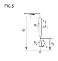
- each resistor in the R-divider or RC divider has a temperature coefficient TK which is less than or equal to the quotient between the maximum permissible change ⁇ TR of the voltage ratio and the maximum temperature difference AT is of the resistors in the divider.
- the primary voltage U P is present at the input and the secondary voltage U S is tapped at the secondary resistor R 2 .
- T 1 is the temperature at resistor R 1 and T 2 is the temperature at resistor R 2 .
- the ohmic values R 1 and R 2 depend on the resistance material used. In practice, the temperature range for the R divider is between 233.3 K (-40 ° C) and 353.3 K (80 ° C). A linear dependence on the temperature can be assumed for the ohmic resistance, which approximately applies to all resistance materials.
- the resistors of the divider are advantageously round resistors, which is an all-ceramic rod with a larger diameter or equal to 7 mm, in particular between 7 and 14 mm, on which a thick film resistance active part with a Thickness greater than or equal to 8 ⁇ m, in particular greater than or equal to 12 ⁇ m, is arranged in a meandering manner.
- the resistors of the divider can also be used, for example Flat resistors are a ceramic plate with a Thickness greater than or equal to 1 mm, in particular between 1.5 and 2 mm, on which a thick film resistance active part with a thickness greater than or equal to 8 ⁇ m, in particular greater than or equal to 12 ⁇ m, is arranged in a meandering manner.
- the round or flat resistors can be designed so that they have negligible self-inductance and that a high surface field strength E perpendicular to the resistive active part layer is permissible.
- the dynamic behavior of the divider can be significantly improved by using sheet resistors instead of wire or ground resistors and by suitably arranging them.
- the divider preferably has a secondary resistor in the form of a tube shunt, in which symmetrical thick-film resistance tracks are arranged on a ceramic tube and a measuring line for taking the secondary voltage U S runs inside the ceramic tube, which is twisted outside the ceramic tube with an earth line.
- the divider can have a secondary resistance comprise, at one end of which a first measuring line is connected and a second test lead that is up to this connection is twisted with the first measuring line, thence to the other end of the secondary resistor in parallel runs to the current path of the secondary resistor and thence with an earth line grounding the secondary resistor twisted and laid to earth.
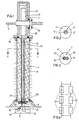
- a first embodiment of a combined small signal current and voltage converter includes an optoelectronic Current transformer and an R divider.
- the primary current of the medium or high voltage system to be measured flows through a primary conductor 6 and is with the optoelectronic current transformers measured.
- a signal processing device 5 polarized light fed into an optical waveguide 13 which passes through a bore of an isolator 4 to an optical one Sensor-forming fiber spool 11 extends.
- the Polarized light then passes through the fiber coil 11, whereby by the magnetic field generated by the current to be measured Plane of polarization of light is rotated and enters the optical fiber 14 and finally back into the Signal processing device 5.
- the rotation of the polarization plane is then in the signal processing device 5 evaluated and converted into electrical signals.
- the optical fiber spool 11 is made of metal in a hood 7 arranged, which is supported by the insulator 4.
- the isolator 4 consists of, for example, porcelain or plastic Silicone shades and has a circular cylindrical interior Drilling on.
- the optical fibers 13 and 14 are in guided a plastic tube 12.
- the voltage measurement takes place with an R-divider 2, which has a chain of round-film resistors 21, which are arranged in the circular-cylindrical bore of the insulator 4.
- One end of the resistance chain is connected to the hood 7, which is under medium or high voltage.
- the last resistor at the other end of the resistor chain comprises the secondary resistor 210.
- This is connected via a measuring line 23 to the signal processing device 5 and via an earth line 22 to the earth.
- the secondary voltage U S is tapped off with the measuring line 23, the signal processing taking place in the signal processing device 5.
- the remaining cavity in the isolator 4 and in the hood 7 is connected to an insulating medium 41, e.g. an elastic Insulating potting compound, an insulating oil or an insulating gas, filled.
- the filling is preferably carried out under vacuum.
- a sealing element 8 with bushings for the plastic pipe 12, the measuring line 23 and the earth line 22 seals the inside of the insulator 4 from the outside.
- For sealing ring seals 90 to 94 are also used.
- a second embodiment of a combined small signal current and voltage converter includes an optoelectronic Current transformer and an RC divider.
- the RC divider comprises a chain of round film resistors 31 in a first circular cylindrical bore an insulator 40 are arranged, and a chain of capacitors 32 in a second circular cylindrical shape Bore of the insulator 40 are arranged.
- the two circular cylindrical Holes overlap easily.
- the resistor chain and the capacitor chain are together electrically connected in a ladder shape.
Landscapes
- Physics & Mathematics (AREA)
- General Physics & Mathematics (AREA)
- Engineering & Computer Science (AREA)
- Power Engineering (AREA)
- Measuring Instrument Details And Bridges, And Automatic Balancing Devices (AREA)
Claims (10)
- Transformateur combiné de courant et de tension pour signal faible pour la mesure du courant et de la tension dans les équipements de commutation à l'air libre, avec un transformateur de courant optoélectronique muni d'une bobine de fibre (11) comme capteur pour la mesure du courant, caractérisé en ce qu'il comprend un diviseur R (2) ou un diviseur RC (3) pour la mesure de la tension, le diviseur (2 ; 3) présentant des résistances (21 ; 31) dont l'inductance propre est inférieure à 200 nH.
- Transformateur combiné de courant et de tension pour signal faible selon la revendication 1, caractérisé en ce qu'il présente un isolateur (4 ; 40) muni d'au moins un orifice dans lequel sont logés les résistances (21 ; 31) du diviseur (2 ; 3), le cas échéant les condensateurs (32) du diviseur RC (3) et un ou deux tubes en plastique (12) avec des fibres optiques (13, 14) du transformateur de courant optoélectronique.
- Transformateur combiné de courant et de tension pour signal faible selon la revendication 2,
caractérisé en ce que l'orifice ou les orifices de l'isolateur (4 ; 40) ont la forme d'un cylindre circulaire ou de deux cylindres circulaires disposés l'un à côté de l'autre qui s'entrecoupent en partie et qui sont remplis d'un moyen isolant (41), plus particulièrement d'une masse de scellement isolante élastique, d'une huile isolante ou d'un gaz isolant. - Transformateur combiné de courant et de tension pour signal faible selon la revendication 2 ou 3, caractérisé en ce que la bobine de fibre (11) pour la mesure du courant et le branchement de la tension primaire du diviseur (2 ; 3) sont disposés d'un côté de l'isolateur (4 ; 40) et un dispositif de traitement du signal (5) est disposé de l'autre côté de l'isolateur (4 ; 40).
- Transformateur combiné de courant et de tension pour signal faible selon l'une des revendications 1 à 4, caractérisé en ce que chaque résistance présente une partie active de résistance à couche épaisse et qu'elle est entourée d'une couche en verre qui rend impossible toute projection de particules résistives de la partie active de résistance à couche épaisse et/ou possède un coefficient de température TK qui est inférieur ou égal au quotient entre la variation maximale admissible ΔTR du rapport de transformation de la tension et la différence de température maximale ΔT des résistances dans le diviseur (2 ; 3).
- Transformateur combiné de courant et de tension pour signal faible selon l'une des revendications 1 à 5, caractérisé en ce que les résistances du diviseur (2 ; 3) sont des résistances rondes qui comprennent une barre en céramique pleine ayant un diamètre supérieur ou égal à 7 mm, plus particulièrement entre 7 et 14 mm, sur laquelle est disposée à la manière de méandres une partie active de résistance à couche épaisse ayant une épaisseur supérieure ou égale à 8 µm, plus particulièrement supérieure ou égale à 12 µm.
- Transformateur combiné de courant et de tension pour signal faible selon la revendication 5 ou 6, caractérisé en ce que chaque résistance présente une inductance propre négligeable inférieure ou égale à 75 nH et elle est pré-vieillie par des impulsions de tension à pente très raide.
- Transformateur combiné de courant et de tension pour signal faible selon l'une des revendications 1 à 7, caractérisé en ce que le diviseur (2 ; 3) présente une partie primaire à laquelle au moine un condensateur supplémentaire est branché en parallèle, le ou les condensateurs supplémentaires ayant une ou des valeurs permettant d'obtenir une fonction de transfert ou de transmission de tension souhaitée.
- Transformateur combiné de courant et de tension pour signal faible selon l'une des revendications 1 à 8, caractérisé en ce que le diviseur (2 ; 3) présente une résistance secondaire sous la forme d'un shunt tubulaire auquel des bandes de résistance à couche épaisse sont disposées de manière symétrique sur un tube en céramique et un fil de mesure destiné à collecter la tension secondaire US s'étend à l'intérieur du tube en céramique et est torsadé à l'extérieur du tube en céramique avec un fil de terre.
- Transformateur combiné de courant et de tension pour signal faible selon l'une des revendications 1 à 9, caractérisé en ce que le diviseur (2 ; 3) comprend une résistance secondaire (210) à une extrémité de laquelle est raccordé un premier fil de mesure (23) et un deuxième fil de mesure est torsadé avec le premier fil de mesure jusqu'à ce point de raccordement, de là il s'étend parallèlement au trajet du courant de la résistance secondaire jusqu'à l'autre extrémité de la résistance secondaire et de là il est torsadé avec un fil de terre (22) qui met la résistance secondaire à la terre puis il est branché à la terre.
Applications Claiming Priority (3)
| Application Number | Priority Date | Filing Date | Title |
|---|---|---|---|
| CH224097 | 1997-09-23 | ||
| CH224097 | 1997-09-23 | ||
| PCT/CH1998/000404 WO1999015906A1 (fr) | 1997-09-23 | 1998-09-21 | Transformateur combine de courant et de tension pour signaux faibles |
Publications (2)
| Publication Number | Publication Date |
|---|---|
| EP1018024A1 EP1018024A1 (fr) | 2000-07-12 |
| EP1018024B1 true EP1018024B1 (fr) | 2001-11-28 |
Family
ID=4229135
Family Applications (1)
| Application Number | Title | Priority Date | Filing Date |
|---|---|---|---|
| EP98942445A Expired - Lifetime EP1018024B1 (fr) | 1997-09-23 | 1998-09-21 | Transformateur combine de courant et de tension pour signaux faibles |
Country Status (3)
| Country | Link |
|---|---|
| EP (1) | EP1018024B1 (fr) |
| DE (1) | DE59802264D1 (fr) |
| WO (1) | WO1999015906A1 (fr) |
Cited By (2)
| Publication number | Priority date | Publication date | Assignee | Title |
|---|---|---|---|---|
| EP2990810A1 (fr) * | 2014-08-29 | 2016-03-02 | Siemens Aktiengesellschaft | Conception de pièce active d'huile dans un gaz |
| RU2608335C2 (ru) * | 2015-04-29 | 2017-01-17 | Федеральное государственное бюджетное образовательное учреждение высшего профессионального образования "Омский государственный технический университет" | Оптико-электронный датчик тока и напряжения |
Families Citing this family (11)
| Publication number | Priority date | Publication date | Assignee | Title |
|---|---|---|---|---|
| US6937026B2 (en) * | 2003-09-11 | 2005-08-30 | Lockheed Martin Corporation | High voltage interface module |
| CN100505120C (zh) * | 2004-11-01 | 2009-06-24 | 王如璋 | 具有光信号输出的干式互感器 |
| CN100543892C (zh) * | 2004-11-01 | 2009-09-23 | 北京瑞恒超高压电器研究所 | 一种具有光信号输出的有机复合绝缘干式电子互感器 |
| RU2365922C1 (ru) * | 2008-04-07 | 2009-08-27 | Общество с ограниченной ответственностью "Технос" | Оптико-электронный датчик тока |
| EP2807664B1 (fr) * | 2011-12-31 | 2016-05-11 | Siemens Aktiengesellschaft | Transformateur combiné pour système d'alimentation |
| CN102832030B (zh) * | 2012-09-17 | 2016-01-20 | 北京水木源华电气股份有限公司 | 一种电子式互感器及制造方法 |
| FR2998376B1 (fr) * | 2012-11-16 | 2015-07-31 | Alstom Technology Ltd | Capteur de tension de ligne a tres haute tension a courant continu |
| CN104459300A (zh) * | 2014-12-23 | 2015-03-25 | 国家电网公司 | 一种与隔离开关组合的支柱式组合电子式互感器 |
| AT521182B1 (de) * | 2018-07-11 | 2019-11-15 | Greenwood Power Og | Spannungsteilungsvorrichtung mit Stäbchenstruktur |
| AT521667B1 (de) * | 2018-07-11 | 2020-09-15 | Greenwood Power Og | Spannungsteilungsvorrichtung mit Siloxan-Dielektrikum |
| AT523120B1 (de) * | 2019-11-14 | 2023-10-15 | Greenwood Power Gmbh | Spannungssensor und Spannungsteilungsvorrichtung |
Family Cites Families (6)
| Publication number | Priority date | Publication date | Assignee | Title |
|---|---|---|---|---|
| US4578639A (en) * | 1984-03-02 | 1986-03-25 | Westinghouse Electric Corp. | Metering system for measuring parameters of high AC electric energy flowing in an electric conductor |
| DE3435418A1 (de) * | 1984-09-27 | 1986-04-03 | C. Schniewindt Kg, 5982 Neuenrade | Gleichspannungsteiler |
| DE3714945A1 (de) * | 1986-05-09 | 1987-11-12 | Koch & Sterzel Kg | Frequenzunabhaengiger kapazitiv-ohmscher spannungsteiler zum messen von hochspannungen in mittel- und hochfrequenten roentgengeneratoren |
| DE4122331A1 (de) * | 1991-04-22 | 1992-10-29 | Asea Brown Boveri | Spannungswandler fuer eine mittel- oder hochspannungsanlage |
| GB2260413B (en) * | 1991-10-11 | 1996-04-24 | Mohammad Javad Birjandi | Search coil for detecting magnetic field components |
| DE4344856A1 (de) * | 1993-12-29 | 1995-07-06 | Abb Research Ltd | Faseroptischer Transmissionssensor mit Modulator |
-
1998
- 1998-09-21 WO PCT/CH1998/000404 patent/WO1999015906A1/fr not_active Ceased
- 1998-09-21 EP EP98942445A patent/EP1018024B1/fr not_active Expired - Lifetime
- 1998-09-21 DE DE59802264T patent/DE59802264D1/de not_active Expired - Lifetime
Cited By (5)
| Publication number | Priority date | Publication date | Assignee | Title |
|---|---|---|---|---|
| EP2990810A1 (fr) * | 2014-08-29 | 2016-03-02 | Siemens Aktiengesellschaft | Conception de pièce active d'huile dans un gaz |
| WO2016030035A1 (fr) * | 2014-08-29 | 2016-03-03 | Siemens Aktiengesellschaft | Conception de partie active d'huile dans un gaz |
| RU2681274C2 (ru) * | 2014-08-29 | 2019-03-05 | Сименс Акциенгезелльшафт | Конструкция масляной активной части в газе |
| US10514395B2 (en) | 2014-08-29 | 2019-12-24 | Siemens Aktiengesellschaft | Method and system for insulating an RC voltage divider with an active part in oil and an outer part in gas |
| RU2608335C2 (ru) * | 2015-04-29 | 2017-01-17 | Федеральное государственное бюджетное образовательное учреждение высшего профессионального образования "Омский государственный технический университет" | Оптико-электронный датчик тока и напряжения |
Also Published As
| Publication number | Publication date |
|---|---|
| DE59802264D1 (de) | 2002-01-10 |
| EP1018024A1 (fr) | 2000-07-12 |
| WO1999015906A1 (fr) | 1999-04-01 |
Similar Documents
| Publication | Publication Date | Title |
|---|---|---|
| EP1018024B1 (fr) | Transformateur combine de courant et de tension pour signaux faibles | |
| EP2092352A1 (fr) | Détecteur de rogowski et procédé de mesure d'un courant | |
| DE3921650A1 (de) | Kapazitiver sensor und elektronische schaltung zur beruehrungslosen abstandsmessung | |
| EP0118147B1 (fr) | Dispositif de résistance de mesure et d'amortissement pour un appareil à haute tension | |
| DE19841164A1 (de) | Spannungsteileranordnung | |
| DE2659807C3 (de) | Kapazitäts-Meßbrücke | |
| DE2603185C2 (de) | Anordnung zur kapazitiven Messung des Füllstandes eines Behälters | |
| DE2819731A1 (de) | Anordnung zur kapazitiven fuellstandsmessung in einem behaelter | |
| DE10005164A1 (de) | Durchführung für eine Hochspannungseinrichtung | |
| WO1990011530A1 (fr) | Dispositif de mesure a electrode auxiliaire pour installations a haute tension blindees isolees au gaz | |
| EP1015895B1 (fr) | Diviseur de tension | |
| DE69019891T2 (de) | Optischer Transformator. | |
| EP4312032B1 (fr) | Dispositif de mesure pour courants alternatifs et haute tension des plasmas physiques | |
| DE4101859C1 (fr) | ||
| DE1473041B2 (de) | Magnetischer Strömungsmesser insbesondere für dielektrische Flüssigkeiten | |
| DE3226387C2 (fr) | ||
| DE19644482C1 (de) | Isolatoranordnung | |
| CH699465A2 (de) | Optische Spannungsmessungsvorrichtung. | |
| EP1782080B1 (fr) | Ensemble pour l'alimentation electrique d'un appareil de mesure | |
| DE2924711C3 (de) | Füllstandsmesser | |
| DE1473041C (de) | Magnetischer Stromungsmesser insbesondere fur dielektrische Flüssigkeiten | |
| DE3701779A1 (de) | Als stromwandler anwendbarer, linear uebertragender messgeber | |
| DE10024335A1 (de) | Ohmscher Spannungsfühler | |
| DE102024204057A1 (de) | Niederinduktiver und breitbandig ausgelegter ohmsch-kapazitiver Spannungsteiler zur Teilentladungsmessung | |
| DE2027735B2 (de) | Messpannungsverteiler fuer eine sehr hohe, mit einer wechselspannung ueberlagerte gleichspannung |
Legal Events
| Date | Code | Title | Description |
|---|---|---|---|
| PUAI | Public reference made under article 153(3) epc to a published international application that has entered the european phase |
Free format text: ORIGINAL CODE: 0009012 |
|
| 17P | Request for examination filed |
Effective date: 20000110 |
|
| AK | Designated contracting states |
Kind code of ref document: A1 Designated state(s): BE CH DE ES FI FR IT LI SE |
|
| GRAG | Despatch of communication of intention to grant |
Free format text: ORIGINAL CODE: EPIDOS AGRA |
|
| 17Q | First examination report despatched |
Effective date: 20010219 |
|
| GRAG | Despatch of communication of intention to grant |
Free format text: ORIGINAL CODE: EPIDOS AGRA |
|
| GRAH | Despatch of communication of intention to grant a patent |
Free format text: ORIGINAL CODE: EPIDOS IGRA |
|
| GRAH | Despatch of communication of intention to grant a patent |
Free format text: ORIGINAL CODE: EPIDOS IGRA |
|
| GRAA | (expected) grant |
Free format text: ORIGINAL CODE: 0009210 |
|
| AK | Designated contracting states |
Kind code of ref document: B1 Designated state(s): BE CH DE ES FI FR IT LI SE |
|
| PG25 | Lapsed in a contracting state [announced via postgrant information from national office to epo] |
Ref country code: IT Free format text: LAPSE BECAUSE OF FAILURE TO SUBMIT A TRANSLATION OF THE DESCRIPTION OR TO PAY THE FEE WITHIN THE PRESCRIBED TIME-LIMIT;WARNING: LAPSES OF ITALIAN PATENTS WITH EFFECTIVE DATE BEFORE 2007 MAY HAVE OCCURRED AT ANY TIME BEFORE 2007. THE CORRECT EFFECTIVE DATE MAY BE DIFFERENT FROM THE ONE RECORDED. Effective date: 20011128 Ref country code: FI Free format text: LAPSE BECAUSE OF FAILURE TO SUBMIT A TRANSLATION OF THE DESCRIPTION OR TO PAY THE FEE WITHIN THE PRESCRIBED TIME-LIMIT Effective date: 20011128 |
|
| REG | Reference to a national code |
Ref country code: CH Ref legal event code: NV Representative=s name: A. BRAUN, BRAUN, HERITIER, ESCHMANN AG PATENTANWAE Ref country code: CH Ref legal event code: EP |
|
| REF | Corresponds to: |
Ref document number: 59802264 Country of ref document: DE Date of ref document: 20020110 |
|
| PG25 | Lapsed in a contracting state [announced via postgrant information from national office to epo] |
Ref country code: SE Free format text: LAPSE BECAUSE OF FAILURE TO SUBMIT A TRANSLATION OF THE DESCRIPTION OR TO PAY THE FEE WITHIN THE PRESCRIBED TIME-LIMIT Effective date: 20020228 |
|
| ET | Fr: translation filed | ||
| PG25 | Lapsed in a contracting state [announced via postgrant information from national office to epo] |
Ref country code: ES Free format text: LAPSE BECAUSE OF FAILURE TO SUBMIT A TRANSLATION OF THE DESCRIPTION OR TO PAY THE FEE WITHIN THE PRESCRIBED TIME-LIMIT Effective date: 20020530 |
|
| PG25 | Lapsed in a contracting state [announced via postgrant information from national office to epo] |
Ref country code: BE Free format text: LAPSE BECAUSE OF NON-PAYMENT OF DUE FEES Effective date: 20020930 |
|
| PLBE | No opposition filed within time limit |
Free format text: ORIGINAL CODE: 0009261 |
|
| STAA | Information on the status of an ep patent application or granted ep patent |
Free format text: STATUS: NO OPPOSITION FILED WITHIN TIME LIMIT |
|
| 26N | No opposition filed | ||
| BERE | Be: lapsed |
Owner name: *TRENCH SWITZERLAND A.G. Effective date: 20020930 |
|
| REG | Reference to a national code |
Ref country code: CH Ref legal event code: PFA Owner name: TRENCH SWITZERLAND AG Free format text: TRENCH SWITZERLAND AG#LEHENMATTSTRASSE 353#4052 BASEL (CH) -TRANSFER TO- TRENCH SWITZERLAND AG#LEHENMATTSTRASSE 353#4052 BASEL (CH) |
|
| REG | Reference to a national code |
Ref country code: CH Ref legal event code: PUE Owner name: TRENCH FRANCE SAS Free format text: TRENCH SWITZERLAND AG#LEHENMATTSTRASSE 353#4052 BASEL (CH) -TRANSFER TO- TRENCH FRANCE SAS#16, RUE DU GENERAL CASSAGNOU BP80070#68302 SAINT LOUIS CEDEX (FR) |
|
| REG | Reference to a national code |
Ref country code: DE Ref legal event code: R082 Ref document number: 59802264 Country of ref document: DE Representative=s name: PATENTANWAELTE STREHL, SCHUEBEL-HOPF & PARTNER, DE Effective date: 20110830 Ref country code: DE Ref legal event code: R081 Ref document number: 59802264 Country of ref document: DE Owner name: TRENCH FRANCE SAS, FR Free format text: FORMER OWNER: TRENCH SWITZERLAND AG, BASEL, CH Effective date: 20110830 |
|
| REG | Reference to a national code |
Ref country code: FR Ref legal event code: TP Owner name: TRENCH FRANCE SAS, FR Effective date: 20110927 |
|
| PGFP | Annual fee paid to national office [announced via postgrant information from national office to epo] |
Ref country code: DE Payment date: 20121120 Year of fee payment: 15 Ref country code: FR Payment date: 20121019 Year of fee payment: 15 Ref country code: CH Payment date: 20121030 Year of fee payment: 15 |
|
| REG | Reference to a national code |
Ref country code: CH Ref legal event code: PL |
|
| REG | Reference to a national code |
Ref country code: FR Ref legal event code: ST Effective date: 20140530 |
|
| REG | Reference to a national code |
Ref country code: DE Ref legal event code: R119 Ref document number: 59802264 Country of ref document: DE Effective date: 20140401 |
|
| PG25 | Lapsed in a contracting state [announced via postgrant information from national office to epo] |
Ref country code: CH Free format text: LAPSE BECAUSE OF NON-PAYMENT OF DUE FEES Effective date: 20130930 Ref country code: LI Free format text: LAPSE BECAUSE OF NON-PAYMENT OF DUE FEES Effective date: 20130930 |
|
| PG25 | Lapsed in a contracting state [announced via postgrant information from national office to epo] |
Ref country code: FR Free format text: LAPSE BECAUSE OF NON-PAYMENT OF DUE FEES Effective date: 20130930 Ref country code: DE Free format text: LAPSE BECAUSE OF NON-PAYMENT OF DUE FEES Effective date: 20140401 |