EP1018024B1 - Combined current/voltage transformer for low level signals - Google Patents
Combined current/voltage transformer for low level signals Download PDFInfo
- Publication number
- EP1018024B1 EP1018024B1 EP98942445A EP98942445A EP1018024B1 EP 1018024 B1 EP1018024 B1 EP 1018024B1 EP 98942445 A EP98942445 A EP 98942445A EP 98942445 A EP98942445 A EP 98942445A EP 1018024 B1 EP1018024 B1 EP 1018024B1
- Authority
- EP
- European Patent Office
- Prior art keywords
- divider
- voltage
- current
- resistor
- signal current
- Prior art date
- Legal status (The legal status is an assumption and is not a legal conclusion. Google has not performed a legal analysis and makes no representation as to the accuracy of the status listed.)
- Expired - Lifetime
Links
Images
Classifications
-
- G—PHYSICS
- G01—MEASURING; TESTING
- G01R—MEASURING ELECTRIC VARIABLES; MEASURING MAGNETIC VARIABLES
- G01R15/00—Details of measuring arrangements of the types provided for in groups G01R17/00 - G01R29/00, G01R33/00 - G01R33/26 or G01R35/00
- G01R15/04—Voltage dividers
- G01R15/06—Voltage dividers having reactive components, e.g. capacitive transformer
-
- G—PHYSICS
- G01—MEASURING; TESTING
- G01R—MEASURING ELECTRIC VARIABLES; MEASURING MAGNETIC VARIABLES
- G01R15/00—Details of measuring arrangements of the types provided for in groups G01R17/00 - G01R29/00, G01R33/00 - G01R33/26 or G01R35/00
- G01R15/14—Adaptations providing voltage or current isolation, e.g. for high-voltage or high-current networks
- G01R15/142—Arrangements for simultaneous measurements of several parameters employing techniques covered by groups G01R15/14 - G01R15/26
-
- G—PHYSICS
- G01—MEASURING; TESTING
- G01R—MEASURING ELECTRIC VARIABLES; MEASURING MAGNETIC VARIABLES
- G01R1/00—Details of instruments or arrangements of the types included in groups G01R5/00 - G01R13/00 and G01R31/00
- G01R1/02—General constructional details
- G01R1/18—Screening arrangements against electric or magnetic fields, e.g. against earth's field
-
- G—PHYSICS
- G01—MEASURING; TESTING
- G01R—MEASURING ELECTRIC VARIABLES; MEASURING MAGNETIC VARIABLES
- G01R15/00—Details of measuring arrangements of the types provided for in groups G01R17/00 - G01R29/00, G01R33/00 - G01R33/26 or G01R35/00
- G01R15/04—Voltage dividers
Landscapes
- Physics & Mathematics (AREA)
- General Physics & Mathematics (AREA)
- Engineering & Computer Science (AREA)
- Power Engineering (AREA)
- Measuring Instrument Details And Bridges, And Automatic Balancing Devices (AREA)
Description
Die Erfindung betrifft einen kombinierten Kleinsignal-Strom- und Spannungswandler für die Strom- und Spannungsmessung in Freiluftschaltanlagen, wie er im Oberbegriff des unabhängigen Patentanspruchs 1 definiert ist.The invention relates to a combined small signal current and voltage converter for current and voltage measurement in Outdoor switchgear, as it is in the generic term of the independent Claim 1 is defined.
Es sind eine Vielzahl von kombinierten bzw. integrierten Kleinsignal-Strom- und Spannungswandlern bekannt, die verschiedene Messprinzipien für die Messung des Primärstromes und der Primärspannung zwischen Phase und Erde bzw. Phase und Nullleiter in Ein-, Zwei- und Drei-Phasensystemen in Mittelspannungs- und Hochspannungsanlagen verwenden. Diese Kleinsignal-Strom- und Spannungswandler unterscheiden sich bei üblichen Eingangsimpedanzen der angeschlossenen Messsysteme in den Übertragungsfunktionen.There are a large number of combined or integrated Small signal current and voltage converters known to be different Measuring principles for measuring the primary current and the primary voltage between phase and earth or phase and neutral in single, two and three phase systems in Use medium voltage and high voltage systems. This Small signal current and voltage converters differ with usual input impedances of the connected measuring systems in the transfer functions.
Standardmässig nach der IEC-Norm 60044-3 (1980) werden kombinierte Kleinsignal-Strom- und Spannungswandler für Mittel- und Hochspannungsanlagen eingesetzt, die auf dem transformatorischen (induktiven) Messprinzip beruhen. Für die Isolation zwischen dem Primär- und dem Sekundärteil der Wandler werden im wesentlichen drei verschiedene Isoliermedien verwendet:
- unelastische Isolierharze (z.B. Epoxydharze, Polyurethanharze);
- Ölpapier oder
- Isoliergase (z.B. SF6)
- inelastic insulating resins (eg epoxy resins, polyurethane resins);
- Oiled paper or
- Insulating gases (e.g. SF 6 )
Der Frequenzbereich f 1 bis f 2 für die Übertragungsfunktion
ist beim transformatorischen Messprinzip ungefähr
Sowohl für die Strom- als auch für die Spannungsmessung ist also die Frequenz f = 0 Hz ausgeschlossen.The frequency f = 0 Hz is therefore excluded for both current and voltage measurement.
Es sind auch kombinierte Kleinsignal-Strom- und Spannungswandler mit einem transformatorischen Spannungswandler und einem optoelektronischen Stromwandler bekannt. Optoelektronische Stromwandler weisen einen Lichtwellenleiter auf, durch den polarisiertes Licht geleitet wird. Aufgrund des Faraday-Effekts wird die Polarisationsebene des Lichts durch das vom zu messenden Strom erzeugte Magnetfeld gedreht. Die Drehung ist proportional zur Magnetfeldstärke und somit zur Stromstärke, so dass durch Messung der Drehung der Polarisationsebene die Stromstärke ermittelt werden kann.They are also combined small signal current and voltage converters with a transformer voltage converter and an optoelectronic current converter known. Optoelectronic Current transformers have an optical fiber, through which polarized light is passed. Because of the Faraday effect becomes the plane of polarization of light rotated by the magnetic field generated by the current to be measured. The rotation is proportional to the magnetic field strength and thus to the current strength, so that by measuring the rotation the current level can be determined in the polarization plane can.
Beim optoelektronischen Stromwandler beginnt der Frequenzbereich für die Übertragungsfunktion bereits bei f 1 = 0 Hz. Ausserdem ist durch den Transport der Messsignale mit Lichtwellenleitern keine Isolation zwischen dem Primärstrom auf Mittel- oder Hochspannungspotential und dem proportionalen Signal auf Erdpotential nötig.With the optoelectronic current transformer, the frequency range for the transfer function already starts at f 1 = 0 Hz.In addition, the transport of the measurement signals with optical fibers means that no isolation between the primary current at medium or high voltage potential and the proportional signal at earth potential is necessary.
Auch dieser kombinierte Kleinsignal-Strom- und Spannungswandler weist aber den Nachteil auf, dass der Frequenzbereich für die Spannungsmessungerst bei ca. f 1 =25 Hz beginnt. Gleichspannung kann also nicht gemessen werden. Zur Isolation zwischen Primärteil und Sekundärteil dienen beim transformatorischen Spannungswandler zudem, wie oben erwähnt, die bekannten Isoliermedien, beispielsweise unelastische Isolierharze, Ölpapier oder Isoliergase. However, this combined small signal current and voltage converter also has the disadvantage that the frequency range for the voltage measurement only begins at approximately f 1 = 25 Hz. DC voltage cannot be measured. For the insulation between the primary part and the secondary part, the known insulation media, for example inelastic insulation resins, oil paper or insulating gases, are also used in the transformer voltage converter, as mentioned above.
In der EP-A-0 156 533 ist ein kombinierter Strom- und Spannungswandler offenbart, der sich aus einem optoelektronischen Stromwandler und einem kapazitiven Spannungsteiler zusammensetzt. Der Stromwandler umfasst magneto-optisches Material, in dem die Polarisationsebene von eingespeistem polarisiertem Licht aufgrund des Faraday-Effekts durch das vom zu messenden Strom erzeugte Magnetfeld gedreht wird. Über eine Kollimatorlinse wird das gedrehte Licht einer Auswerteelektronik zugeführt. Der kapazitive Spannungsteiler weist den Nachteil auf, dass er physikalisch nicht in der Lage ist, Spannungen im Frequenzbereich 0 bis 5 Hz genügend exakt zu erfassen.In EP-A-0 156 533 there is a combined current and voltage converter disclosed, which consists of an optoelectronic Current transformer and a capacitive voltage divider. The current transformer comprises magneto-optical material, in which the polarization plane of fed polarized Light due to the Faraday effect by the from generated magnetic field to be measured is rotated. about a collimator lens turns the rotated light of an evaluation electronics fed. The capacitive voltage divider has the disadvantage of being physically unable is, voltages in the frequency range 0 to 5 Hz are sufficiently precise capture.
In der DE-A-34 35 418 ist ein kombinierter Strom- und Spannungswandler beschrieben, bei dem die Strommessung mit einem Shunt ausgeführt und erst danach durch Umwandlung ein optisches Signal erzeugt wird. Die Spannungsmessung erfolgt mit einem RC-Teiler, dessen Sekundärabgriff sich auf Hochspannungspotential befindet, dessen Aufbau aber nicht im Detail erläutert ist. Insbesondere geht nicht hervor, was für Widerstände verwendet werden.DE-A-34 35 418 is a combined current and voltage converter described, in which the current measurement with a Executed shunt and only then by conversion to an optical one Signal is generated. The voltage measurement is done with an RC divider, whose secondary tap is at high voltage potential is located, but its structure is not in detail is explained. In particular, it is not clear what kind of resistances be used.
Aus der DE-A-37 14 945 ist ein frequenzunabhängiger RC-Teiler zum Messen von Spannungen bis 150 kV in mittel- und hochfrequenten Röntgengeneratoren bekannt. Der RC-Teiler weist einen innerhalb des Röntgengenerators angeordneten niederinduktiven Teilwiderstand auf, dessen Aktivteil aber aufgrund des sehr geringen Abstands zur Hochspannungselektrode und zur Erdelektrode und aufgrund des eckig mäanderförmigen Verlaufs bei Hochspannung Überschlägen ausgesetzt ist und keine dauernde Stabilität des Übersetzungsverhältnisses gewährleistet. Darüberhinaus ist ein ausserhalb des Röntgengenerators angeordneter Teilwiderstand vorhanden, der nicht detailliert erläutert ist. Der beschriebene RC-Teiler ist für hohe und für niederfrequente Spannungen nicht geeignet.DE-A-37 14 945 is a frequency-independent RC divider for measuring voltages up to 150 kV in medium and known high-frequency X-ray generators. The RC divider has one arranged within the X-ray generator low inductive partial resistance, but its active part due to the very short distance to the high voltage electrode and to the earth electrode and due to the angular meandering shape Flashover exposed to high voltage is and no permanent stability of the gear ratio guaranteed. In addition, an outside of the X-ray generator arranged partial resistance available that is not explained in detail. The described RC divider is not suitable for high and low frequency voltages.
Die EP-A-0 510 427 offenbart einen R-Teiler, der ausgebildet ist, um in einem Innenraum einer Schaltanlage eingesetzt zu werden, und daher nicht ohne weiteres mit einem Stromwandler kombinierbar ist. Der Aufbau und die Eigenschaften der in Dickschichttechnologie hergestellten Widerstände des R-Teilers sind nicht genau angegeben.EP-A-0 510 427 discloses an R-divider that is formed is to be used in an interior of a switchgear be, and therefore not easily with a current transformer can be combined. The structure and properties of the in Thick film technology manufactured resistors of the R divider are not specified.
Im Artikel "INSTRUMENT HIGH-VOLTAGE DIVIDER WITH METAL-FILM RESISTORS" von N.I. Fal'kovskii aus Measurement Techniques, Band 18, Nr. 2, Seite 297, Plenum Publishing Corporation, ist ein R-Teiler mit Metallfilmwiderständen beschrieben. Die Widerstände sind in bifilarer Anordnung in einem Glasrohr fixiert. In der Praxis hat sich gezeigt, dass derartige R-Teiler für den Einsatz in der Hochspannungsmesstechnik für Energieübertragungsnetze ungeeignet sind, da schnelländernde Spannungen, wie sie bei Kurzschlüssen in Hochspannungsnetzen auftreten, schnelländernde elektrische Felder zur Folge haben, die die Widerstandsstruktur und damit den Widerstandswert verändern.In the article "INSTRUMENT HIGH-VOLTAGE DIVIDER WITH METAL-FILM RESISTORS "by N.I. Fal'kovskii from Measurement Techniques, Volume 18, No. 2, page 297, Plenum Publishing Corporation, describes an R divider with metal film resistors. The Resistors are in a bifilar arrangement in a glass tube fixed. In practice it has been shown that such R-dividers for use in high voltage measurement technology for Energy transmission networks are unsuitable because of fast changing Voltages, such as those in the event of short circuits in high-voltage networks occur, result in rapidly changing electrical fields, which the resistance structure and thus the resistance value change.
Angesichts der Nachteile der bisher bekannten Vorrichtungen liegt der Erfindung die folgende Aufgabe zugrunde. Zu schaffen ist ein kombinierter Kleinsignal-Strom- und Spannungswandler, dessen Übertragungsfunktion für die Strom- und Spannungsmessung bei der Frequenz f 1 = 0 Hz (Gleichspannung/ Gleichstrom) anfängt und bis zu einer oberen Frequenz f 2 ≥ 20 kHz geht und auch auf höhere Frequenzen erweiterbar ist. Es soll zudem auf eine Isolation zwischen dem Mittel- oder Hochspannungspotential, auf dem der Primärstrom gemessen werden soll, und der Erde bzw. eine Isolation für die Messung der Primärspannung und Sekundärspannung mittels unelastischer Isolierharze, Ölpapier oder Isoliergase verzichtet werden können.In view of the disadvantages of the previously known devices, the invention is based on the following object. A combined small signal current and voltage converter has to be created, the transfer function for the current and voltage measurement starting at the frequency f 1 = 0 Hz (direct voltage / direct current) and going up to an upper frequency f 2 ≥ 20 kHz and also to higher ones Frequencies is expandable. It should also be possible to dispense with insulation between the medium or high voltage potential at which the primary current is to be measured and the earth or insulation for measuring the primary voltage and secondary voltage by means of inelastic insulating resins, oil paper or insulating gases.
Diese Aufgabe wird durch den erfindungsgemässen kombinierten Kleinsignal-Strom- und Spannungswandler gelöst, wie er im unabhängigen Patentanspruch 1 definiert ist. Bevorzugte Ausführungsvarianten ergeben sich aus den abhängigen Patentansprüchen.This object is combined by the inventive one Small signal current and voltage converter solved like him is defined in independent claim 1. Preferred Design variants result from the dependent patent claims.
Das Wesen der Erfindung besteht darin, dass ein kombinierter Kleinsignal-Strom- und Spannungswandler für die Strom- und Spannungsmessung in Freiluftschaltanlagen einen R-Teiler oder RC-Teiler für die Spannungsmessung umfasst, wobei der Teiler Widerstände mit einer Eigeninduktivität kleiner als 200 nH aufweist. Die Strommessung erfolgt mit einem optoelektronischen Stromwandler mit einer Faserspule als Sensor.The essence of the invention is that a combined Small signal current and voltage converters for the current and voltage measurement in outdoor switchgear an R-divider or RC divider for voltage measurement, wherein the divider resistors with a self-inductance smaller than 200 nH. The current is measured using an optoelectronic Current transformer with a fiber coil as a sensor.
Widerstände mit einer Eigeninduktivität kleiner als 200 nH, d.h. niederinduktive Widerstände, zeichnen sich dadurch aus, dass sie beim Durchfluss von Strom nur ein sehr kleines Magnetfeld erzeugen, was durch eine spezielle Anordnung des Widerstandsdrahtes oder der Widerstandsbahn erreicht wird. Bekannt sind beispielsweise eine bifilare Wicklung mit eng aneinander gewickelten Wicklungsdrähten oder die Ausbildung als Massewiderstand oder Metallfolienwiderstand mit einer sehr dünnen Metallfolie. Auch Dickschichtwiderstände können durch geeignete, beispielsweise mäanderförmige, Anordnung von dünnen Widerstandsbahnen eine kleine Eigeninduktivität aufweisen. Wichtig ist die Vermeidung von Magnetfeld erzeugenden Flächen zwischen Widerstandsbahnen oder als Alternative das gegenseitige Aufheben von Magnetfeldern.Resistors with an inductance less than 200 nH, i.e. low inductance resistors from that they are only a very small when flow of electricity Magnetic field generate what through a special arrangement of the resistance wire or the resistance track becomes. For example, a bifilar winding is known with tightly wound winding wires or the Training as mass resistance or metal foil resistance with a very thin metal foil. Even thick film resistors by suitable, for example meandering, Arrangement of thin resistance tracks a small one Have self-inductance. It is important to avoid Areas generating magnetic fields between resistance tracks or alternatively the mutual cancellation of magnetic fields.
Mit einem erfindungsgemäss ausgebildeten kombinierten Kleinsignal-Strom- und Spannungswandler sind Strom und Spannung bei Frequenzen zwischen 0 Hz und mindestens 20 kHz messbar. Für die Strommessung wird dies durch den optoelektronischen Stromwandler und für die Spannungsmessung durch den R-Teiler oder den RC-Teiler ermöglicht. Der R-Teiler ist in Freiluft-Kleinsignal-Strom- und Spannungswandlern mit vorgegebener Überschlagsdistanz und dazu gehörigen sehr kleinen Werten für die Streukapazitäten gegen Erde verwendbar, nicht aber für gasisolierte Schaltanlagen, da dort durch den gedrängten Aufbau die Werte für die Streukapazitäten bei einem R-Teiler sehr hoch sind. Der RC-Teiler ist in kombinierten Kleinsignal-Strom- und Spannungswandlern sowohl für Freiluftschaltanlagen als auch für gasisolierte Schaltanlagen geeignet..With a combined designed according to the invention Small signal current and voltage converters are current and Voltage at frequencies between 0 Hz and at least 20 kHz measurable. For the current measurement, this is done by the optoelectronic Current transformer and for voltage measurement by enables the R divider or the RC divider. The R divider is in outdoor small signal current and voltage converters with a predetermined rollover distance and very much associated with it small values for the stray capacities against earth can be used, but not for gas-insulated switchgear, because there due to the compact structure, the values for the stray capacities are very high with an R-divider. The RC divider is in combined small signal current and voltage converters both for outdoor switchgear and for gas-insulated Switchgear suitable ..
Der R-Teiler oder RC-Teiler und der optoelektronische Stromwandler ermöglichen es ausserdem, auf den Einsatz von unelastischen Isolierharzen, Ölpapier oder Isoliergasen als Isoliermedien zu verzichten. Der optoelektronische Stromwandler erfordert, wie schon erwähnt, durch den Transport der Messsignale mit Lichtwellenleitern keine Isolation zwischen dem Primärstrom auf Mittel- oder Hochspannungspotential und dem proportionalen Signal auf Erdpotential, während beim Teiler die Isolation beispielsweise mit einer elastischen Isolier-Vergussmasse erfolgen kann. The R divider or RC divider and the optoelectronic current transformer also make it possible to use non-elastic Insulating resins, oil paper or insulating gases as insulating media to renounce. The optoelectronic current transformer requires, as already mentioned, by the transport of the measurement signals with optical fibers no insulation between the Primary current at medium or high voltage potential and that proportional signal to ground potential while at the divider the insulation, for example, with an elastic insulating casting compound can be done.
Ein wichtiger Vorteil des R-Teilers oder des RC-Teilers ist zudem die zwangsläufig vorhandene lineare Steuerung des Potentials zwischen Hochspannung und Erde, d.h. dass der Abbau des Potentials von der Hochspannung zur Erde linear längs der Isolation verläuft.An important advantage of the R divider or the RC divider is also the inevitable linear control of the potential between high voltage and earth, i.e. that the breakdown the potential from high voltage to earth linear runs along the insulation.
Vorzugsweise besitzt jeder Widerstand im R-Teiler oder RC-Teiler einen Temperaturkoeffizienten TK, der kleiner oder gleich dem Quotienten zwischen der maximal zulässigen Änderung ΔTR des Spannungs-Übersetzungsverhältnisses und der maximalen Temperaturdifferenz ΔT der Widerstände im Teiler ist.Preferably, each resistor in the R-divider or RC divider has a temperature coefficient TK which is less than or equal to the quotient between the maximum permissible change Δ TR of the voltage ratio and the maximum temperature difference AT is of the resistors in the divider.
Darf die Änderung ΔTR des Spannungs-Übersetzungsverhältnisses nicht grösser als 10-4 sein, ergibt sich somit für eine Temperaturdifferenz ΔT im Teiler von 10 K ein Temperaturkoeffizient TK≤ Δ TR / Δ T = 10-4 / 10K= 10·10-6 1 / K. Auf diese Weise kann derIf the change Δ TR in the voltage transmission ratio must not be greater than 10 -4 , a temperature coefficient TK ≤ Δ TR / Δ T = 10 -4 / 10 K = 10 · 10 - results for a temperature difference ΔT in the divisor of 10 K 6 1 / K. In this way, the
Einfluss der Temperatur auf die Spannungsmessung reduziert und damit die Messgenauigkeit erhöht werden.Influence of temperature on voltage measurement reduced and thus the measuring accuracy can be increased.
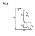
Im folgenden wird diese Beziehung unter Bezugnahme auf Fig. 5 hergeleitet, in der das elektrische Schema eines R-Teilers dargestellt ist.In the following this relationship is explained with reference to FIG. 5 derived in which the electrical scheme of an R divider is shown.
Am Eingang liegt die Primärspannung UP und am Sekundärwiderstand
R2 wird die Sekundärspannung US abgegriffen. Im
Widerstand R1 wird die Leistung P1 = I2 · R1 und im Widerstand
R2 die Leistung P2 = I2 · R2 umgesetzt. Der Strom I ist
durch die Beziehung
Die Leistung P1 erwärmt den Widerstand R1 um ΔT 1 = T 1 - T 0 und die Leistung P2 erwärmt den Widerstand R2 um ΔT 2 = T 2 - T 0. Die Temperatur T0 ist dabei die Umgebungstemperatur. Sie wird für Berechnungen meistens als T0 = 20°C = 293.3 K angenommen. T1 ist die Temperatur am Widerstand R1 und T2 die Temperatur am Widerstand R2.The power P 1 heats the resistor R 1 by ΔT 1 = T 1 - T 0 and the power P 2 heats the resistor R 2 by Δ T 2 = T 2 - T 0 . The temperature T 0 is the ambient temperature. For calculations, it is usually assumed to be T 0 = 20 ° C = 293.3 K. T 1 is the temperature at resistor R 1 and T 2 is the temperature at resistor R 2 .
Die Sekundärspannung US ist durch die Gleichung
Die Ohmwerte R1 und R2 hängen vom eingesetzten Widerstandsmaterial ab. In der Praxis liegt der Temperatureinsatzbereich für den R-Teiler zwischen 233.3 K (-40°C) und 353.3 K (80°C). Für den ohmschen Widerstand kann eine lineare Abhängigkeit von der Temperatur angenommen werden, die näherungsweise für alle Widerstandsmaterialien zutrifft.The ohmic values R 1 and R 2 depend on the resistance material used. In practice, the temperature range for the R divider is between 233.3 K (-40 ° C) and 353.3 K (80 ° C). A linear dependence on the temperature can be assumed for the ohmic resistance, which approximately applies to all resistance materials.
Für die Widerstände R1(T) und R2(T) gelten die Beziehungen
(siehe R. Paul, Elektrotechnik, Springer Verlag, 1985, ISBN
3-540-13633-9, Seite 74)
![]()
![]()
![]()
![]()
In den Gleichungen (3) und (4) ist TK der Temperaturkoeffizient
des eingesetzten Widerstandsmaterials. Werden die
Gleichungen (3) und (4) in Gleichung (2) eingesetzt, so
gilt:
Aus (5) folgt:
Haben die Widerstände R1 und R2 die gleichen Temperaturen
T1 = T2 beziehungsweise ΔT1 = ΔT2, so vereinfacht sich die
Gleichung (6) zu
Für eine geforderte Genauigkeitsklasse des Messsystems von
0.1 % = and 10-3 sollte die Abweichung ΔTR des Übersetzungsverhältnisses
des Teilers in Abhängigkeit der Temperaturen T1
und T2 bzw. ΔT1 und ΔT2
Mit R10 >> R20 ist R 20 / R 10 << 1, damit folgt aus Gleichung (9) :
Mit ΔT1 - ΔT2 = T1 - T0 - T2 + T0 = ΔT (11)
ergibt sich
Da die Temperaturkoeffizienten TK von Widerstandsmaterialien
in der Grössenordnung von 10-5 liegen und die Temperaturerhöhung
ΔT2 ≤ 50°C ist, ist in der Gleichung (12) das
Produkt ΔT2 · TK << 1 und aus Gleichung (12) folgt:
Aus Gleichung (13) folgt für eine Temperaturdifferenz von
ΔT = T1 - T2 = 10 K = 10°C an den Widerständen R1 und R2 ein
maximaler Temperaturkoeffizent
Mit Vorteil sind die Widerstände des Teilers Rundwiderstände, die einen Vollkeramikstab mit einem Durchmesser grösser oder gleich 7 mm, insbesondere zwischen 7 und 14 mm, umfassen, auf dem ein Dickschichtwiderstandsaktivteil mit einer Dicke grösser oder gleich 8 µm, insbesondere grösser oder gleich 12 µm, mäanderartig angeordnet ist.The resistors of the divider are advantageously round resistors, which is an all-ceramic rod with a larger diameter or equal to 7 mm, in particular between 7 and 14 mm, on which a thick film resistance active part with a Thickness greater than or equal to 8 µm, in particular greater than or equal to 12 µm, is arranged in a meandering manner.
Die Widerstände des Teilers können beispielsweise auch Flachwiderstände sind, die eine Keramikplatte mit einer Dicke grösser oder gleich 1 mm, insbesondere zwischen 1,5 und 2 mm, umfassen, auf der ein Dickschichtwiderstandsaktivteil mit einer Dicke grösser oder gleich 8 µm, insbesondere grösser oder gleich 12 µm, mäanderartig angeordnet ist.The resistors of the divider can also be used, for example Flat resistors are a ceramic plate with a Thickness greater than or equal to 1 mm, in particular between 1.5 and 2 mm, on which a thick film resistance active part with a thickness greater than or equal to 8 µm, in particular greater than or equal to 12 µm, is arranged in a meandering manner.
Die Rund- oder Flachwiderstände können so ausgebildet werden,
dass sie eine vernachlässigbare Eigeninduktivität besitzen
und dass eine hohe Oberflächenfeldstärke
Vorzugsweise weist der Teiler einen Sekundärwiderstand in Form eines Röhrenshunts auf, bei dem auf einem Keramikrohr symmetrische Dickschichtwiderstandsbahnen angeordnet sind und im Innern des Keramikrohrs eine Messleitung zur Abnahme der Sekundärspannung US verläuft, die ausserhalb des Keramikrohrs mit einer Erdleitung verdrillt ist.The divider preferably has a secondary resistor in the form of a tube shunt, in which symmetrical thick-film resistance tracks are arranged on a ceramic tube and a measuring line for taking the secondary voltage U S runs inside the ceramic tube, which is twisted outside the ceramic tube with an earth line.
Auf diese Weise heben sich bei der Spannungsmessung die durch ein störendes Magnetfeld induzierten Spannungen gegenseitig auf, so dass die Messung der Primärspannung UP durch diese nicht verfälscht wird. In this way, the voltages induced by a disturbing magnetic field cancel each other out during the voltage measurement, so that the measurement of the primary voltage U P is not falsified by them.
Als Alternative kann der Teiler einen Sekundärwiderstand umfassen, an dessen einem Ende ein erste Messleitung angeschlossen ist, und eine zweite Messleitung, die bis zu diesem Anschluss mit der ersten Messleitung verdrillt ist, von dort bis zum anderen Ende des Sekundärwiderstands parallel zum Strompfad des Sekundärwiderstands verläuft und von dort mit einer den Sekundärwiderstand erdenden Erdleitung verdrillt und an die Erde gelegt ist.Alternatively, the divider can have a secondary resistance comprise, at one end of which a first measuring line is connected and a second test lead that is up to this connection is twisted with the first measuring line, thence to the other end of the secondary resistor in parallel runs to the current path of the secondary resistor and thence with an earth line grounding the secondary resistor twisted and laid to earth.
Bei einem derartig ausgebildeten Teiler sind die spannungsinduzierenden Flächen und somit die induzierten Spannungen sehr klein, so dass die Messung der Primärspannung UP durch diese deutlich weniger verfälscht wird als bei bisher bekannten Teilern.In a divider designed in this way, the voltage-inducing areas and thus the induced voltages are very small, so that the measurement of the primary voltage U P is significantly less falsified by this than in previously known dividers.
Im folgenden wird der erfindungsgemässe kombinierte Kleinsignal-Strom- und Spannungswandler unter Bezugnahme auf die beigefügten Zeichnungen anhand von zwei Ausführungsbeispielen detaillierter beschrieben. Es zeigen:
- Fig. 1 -
- eine Schnittansicht eines ersten Ausführungsbeispiels eines kombinierten Kleinsignal-Strom- und Spannungswandlers mit einem R-Teiler;
- Fig. 2 -
- einen Horizontalschnitt des kombinierten Kleinsignal-Strom- und Spannungswandlers von Fig. 1 gemäss der Linie I-I;
- Fig. 3 -
- einen Horizontalschnitt eines zweiten Ausführungsbeispiels eines kombinierten Kleinsignal-Strom- und Spannungswandlers mit einem RC-Teiler und
- Fig. 4 -
- ein Schema eines Teils des RC-Teilers des zweiten Ausführungsbeispiels.
- Fig.5 -
- ein Schema eines einfachen R-Teilers
- Fig. 1 -
- a sectional view of a first embodiment of a combined small signal current and voltage converter with an R divider;
- Fig. 2 -
- a horizontal section of the combined small signal current and voltage converter of Figure 1 along the line II.
- Fig. 3 -
- a horizontal section of a second embodiment of a combined small signal current and voltage converter with an RC divider and
- Fig. 4 -
- a diagram of part of the RC divider of the second embodiment.
- Fig. 5 -
- a schematic of a simple R-divider
Ein erstes Ausführungsbeispiel eines kombinierten Kleinsignal-Strom- und Spannungswandlers umfasst einen optoelektronischen Stromwandler und einen R-Teiler.A first embodiment of a combined small signal current and voltage converter includes an optoelectronic Current transformer and an R divider.
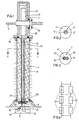
Der zu messende Primärstrom der Mittel- oder Hochspannungsanlage fliesst durch einen Primärleiter 6 und wird mit dem optoelektronischen Stromwandler gemessen. Hierzu wird in einer Signalverarbeitungseinrichtung 5 polarisiertes Licht in einen Lichtwellenleiter 13 eingespeist, der sich durch eine Bohrung eines Isolators 4 hindurch zu einer einen optischen Sensor bildenden Faserspule 11 hin erstreckt. Das polarisierte Licht durchläuft dann die Faserspule 11, wobei durch das vom zu messenden Strom erzeugte Magnetfeld die Polarisationsebene des Lichts gedreht wird, und gelangt in den Lichtwellenleiter 14 und schliesslich wieder in die Signalverarbeitungseinrichtung 5. Die Drehung der Polarisationsebene wird darauf in der Signalverarbeitungseinrichtung 5 ausgewertet und in elektrische Signale umgesetzt.The primary current of the medium or high voltage system to be measured flows through a primary conductor 6 and is with the optoelectronic current transformers measured. For this, in a signal processing device 5 polarized light fed into an optical waveguide 13 which passes through a bore of an isolator 4 to an optical one Sensor-forming fiber spool 11 extends. The Polarized light then passes through the fiber coil 11, whereby by the magnetic field generated by the current to be measured Plane of polarization of light is rotated and enters the optical fiber 14 and finally back into the Signal processing device 5. The rotation of the polarization plane is then in the signal processing device 5 evaluated and converted into electrical signals.
Die optische Faserspule 11 ist in einer Haube 7 aus Metall angeordnet, die vom Isolator 4 getragen wird. Der Isolator 4 besteht beispielsweise aus Porzellan oder Kunststoff mit Silikonschirmen und weist im Innern eine kreiszylinderförmige Bohrung auf. Die Lichtwellenleiter 13 und 14 sind in einem Kunststoffrohr 12 geführt.The optical fiber spool 11 is made of metal in a hood 7 arranged, which is supported by the insulator 4. The isolator 4 consists of, for example, porcelain or plastic Silicone shades and has a circular cylindrical interior Drilling on. The optical fibers 13 and 14 are in guided a plastic tube 12.
Die Spannungsmessung erfolgt mit einem R-Teiler 2, welcher eine Kette von Rundschichtwiderständen 21 aufweist, die in der kreiszylinderförmigen Bohrung des Isolators 4 angeordnet sind. Das eine Ende der Widerstandskette ist mit der unter Mittel- oder Hochspannung stehenden Haube 7 verbunden. Der letzte Widerstand am anderen Ende der Widerstandskette umfasst den Sekundärwiderstand 210. Dieser ist über eine Messleitung 23 mit der Signalverarbeitungseinrichtung 5 und über ein Erdleitung 22 mit der Erde verbunden. Die Sekundärspannung US wird mit der Messleitung 23 abgegriffen, wobei die Signalverarbeitung in der Signalverarbeitungseinrichtung 5 erfolgt.The voltage measurement takes place with an R-divider 2, which has a chain of round-film resistors 21, which are arranged in the circular-cylindrical bore of the insulator 4. One end of the resistance chain is connected to the hood 7, which is under medium or high voltage. The last resistor at the other end of the resistor chain comprises the secondary resistor 210. This is connected via a measuring line 23 to the signal processing device 5 and via an earth line 22 to the earth. The secondary voltage U S is tapped off with the measuring line 23, the signal processing taking place in the signal processing device 5.
Der übrig bleibende Hohlraum im Isolator 4 und in der Haube 7 ist mit einem Isoliermedium 41, z.B. einer elastischen Isolier-Vergussmasse, einem Isolieröl oder einem Isoliergas, gefüllt. Das Füllen erfolgt vorzugsweise unter Vakuum. Ein Abdichtelement 8 mit Durchführungen für das Kunststoffrohr 12, die Messleitung 23 und die Erdleitung 22 dichtet das Innere des Isolators 4 nach aussen ab. Zur Abdichtung dienen ausserdem auch Ringdichtungen 90 bis 94.The remaining cavity in the isolator 4 and in the hood 7 is connected to an insulating medium 41, e.g. an elastic Insulating potting compound, an insulating oil or an insulating gas, filled. The filling is preferably carried out under vacuum. A sealing element 8 with bushings for the plastic pipe 12, the measuring line 23 and the earth line 22 seals the inside of the insulator 4 from the outside. For sealing ring seals 90 to 94 are also used.
Ein zweites Ausführungsbeispiel eines kombinierten Kleinsignal-Strom- und Spannungswandlers umfasst einen optoelektronischen Stromwandler und einen RC-Teiler.A second embodiment of a combined small signal current and voltage converter includes an optoelectronic Current transformer and an RC divider.
Der RC-Teiler umfasst eine Kette von Rundschichtwiderständen 31, die in einer ersten kreiszylinderförmigen Bohrung eines Isolators 40 angeordnet sind, und eine Kette von Kondensatoren 32, die in einer zweiten kreiszylinderförmigen Bohrung des Isolators 40 angeordnet sind. Die beiden kreiszylinderförmigen Bohrungen überschneiden sich leicht. Die Widerstandskette und die Kondensatorkette sind miteinander leiterförmig elektrisch verbunden.The RC divider comprises a chain of round film resistors 31 in a first circular cylindrical bore an insulator 40 are arranged, and a chain of capacitors 32 in a second circular cylindrical shape Bore of the insulator 40 are arranged. The two circular cylindrical Holes overlap easily. The The resistor chain and the capacitor chain are together electrically connected in a ladder shape.
In der die Kondensatorkette enthaltenden Bohrung ist auch das Kunststoffrohr 12 mit den beiden Lichtwellenleitern 13 und 14 angeordnet.There is also a hole in the condenser chain the plastic tube 12 with the two optical fibers 13 and 14 arranged.
Die restlichen Teile sowie die Funktionsweise entsprechen dem ersten Ausführungsbeispiel. The remaining parts and the mode of operation correspond the first embodiment.
Zu den vorbeschriebenen kombinierten Kleinsignal-Strom- und Spannungswandlern sind weitere konstruktive Variationen realisierbar. Hier ausdrücklich erwähnt sei, dass die beiden Lichtwellenleiter 13 und 14 in zwei verschiedenen Kunststoffrohren angeordnet sein können.To the combined small signal current and Voltage transformers can be implemented in other design variations. It should be explicitly mentioned here that the two Optical fibers 13 and 14 in two different plastic tubes can be arranged.
Claims (10)
- Combined small-signal current and voltage transformer for current and voltage measurement in outdoor switchgear assemblies, having an optoelectronic current transformer with a fibre coil (11) as the sensor for current measurement, characterized in that said transformer comprises an R-divider (2) or RC divider (3) for the voltage measurement, with the divider (2; 3) having resistors (21; 31) with self-inductance of less than 200 nH.
- Combined small-signal current and voltage transformer according to Claim 1, characterized in that said transformer has an insulator (4; 40) which is provided with at least one hole and in which the resistors (21; 31) of the divider (2; 3), possibly the capacitors (32) of the RC divider (3), and one or two plastic tubes (12) with optical waveguides (13, 14) of the optoelectronic current transformer are arranged.
- Combined small-signal current and voltage transformer according to Claim 2, characterized in that the hole or holes in the insulator (4; 40) is or are in the form of a circular cylinder or of two circular cylinders which are arranged alongside one another such that they partially overlap, and are filled with an insulating medium (41), in particular an elastic insulating encapsulation compound, an insulating oil or an insulating gas.
- Combined small-signal current and voltage transformer according to Claim 2 or 3, characterized in that the fibre coil (11) for current measurement, and the primary voltage connection of the divider (2; 3), are arranged on one side of the insulator (4; 40), and a signal processing device (5) is arranged on the other side of the insulator (4; 40).
- Combined small-signal current and voltage transformer according to one of Claims 1 to 4, characterized in that each resistor has a thick-film resistor active part and is surrounded by a glass layer, which makes it impossible for particles of the resistor to be torn out of the thick-film resistor active part, and/or has a temperature coefficient TK which is less than or equal to the quotient between the maximum possible change ΔTR in the voltage transformation ratio and the maximum temperature difference ΔT of the resistors in the divider (2; 3).
- Combined small-signal current and voltage transformer according to one of Claims 1 to 5, characterized in that the resistors in the divider (2; 3) are round resistors, which comprise a solid ceramic rod with a diameter of greater than or equal to 7 mm, in particular between 7 and 14 mm, on which a thick-film resistor active part with a thickness of greater than or equal to 8 µm, in particular greater than or equal to 12 µm, is arranged in a meandering shape.
- Combined small-signal current and voltage transformer according to Claim 5 or 6, characterized in that each resistor has a negligible self inductance of less than or equal to 75 nH, and is pre-aged by means of voltage pulses with a steep gradient.
- Combined small-signal current and voltage transformer according to one of Claims 1 to 7, characterized in that the divider (2; 3) has a primary part, in parallel with which at least one additional capacitance is connected, with the additional capacitance or capacitances having a value or values such that a desired voltage transfer or transmission function is obtained.
- Combined small-signal current and voltage transformer according to one of Claims 1 to 8, characterized in that the divider (2; 3) has a secondary resistor in the form of a tubular shunt, in which symmetrical thick-film resistor tracks are arranged on a ceramic tube, and a measurement line for tapping off the secondary voltage US is arranged in the interior of the ceramic tube, and is twisted with an earth line outside the ceramic tube.
- Combined small-signal current and voltage transformer according to one of Claims 1 to 9, characterized in that the divider (2; 3) comprises a secondary resistor (210) to one of whose ends a first measurement line (23) is connected, and a second measurement line is twisted with the first measurement line as far as this connection, runs parallel to the current path of the secondary resistor from there to the other end of the secondary resistor, and, from there, is twisted with an earth line (22) which earths the secondary resistor, and is connected to earth.
Applications Claiming Priority (3)
| Application Number | Priority Date | Filing Date | Title |
|---|---|---|---|
| CH224097 | 1997-09-23 | ||
| CH224097 | 1997-09-23 | ||
| PCT/CH1998/000404 WO1999015906A1 (en) | 1997-09-23 | 1998-09-21 | Combined current/voltage transformer for low level signals |
Publications (2)
| Publication Number | Publication Date |
|---|---|
| EP1018024A1 EP1018024A1 (en) | 2000-07-12 |
| EP1018024B1 true EP1018024B1 (en) | 2001-11-28 |
Family
ID=4229135
Family Applications (1)
| Application Number | Title | Priority Date | Filing Date |
|---|---|---|---|
| EP98942445A Expired - Lifetime EP1018024B1 (en) | 1997-09-23 | 1998-09-21 | Combined current/voltage transformer for low level signals |
Country Status (3)
| Country | Link |
|---|---|
| EP (1) | EP1018024B1 (en) |
| DE (1) | DE59802264D1 (en) |
| WO (1) | WO1999015906A1 (en) |
Cited By (2)
| Publication number | Priority date | Publication date | Assignee | Title |
|---|---|---|---|---|
| EP2990810A1 (en) * | 2014-08-29 | 2016-03-02 | Siemens Aktiengesellschaft | Oil active part design in gas |
| RU2608335C2 (en) * | 2015-04-29 | 2017-01-17 | Федеральное государственное бюджетное образовательное учреждение высшего профессионального образования "Омский государственный технический университет" | Optical-electronic current and voltage sensor |
Families Citing this family (9)
| Publication number | Priority date | Publication date | Assignee | Title |
|---|---|---|---|---|
| US6937026B2 (en) * | 2003-09-11 | 2005-08-30 | Lockheed Martin Corporation | High voltage interface module |
| CN100505120C (en) * | 2004-11-01 | 2009-06-24 | 王如璋 | Dry type mutual inductor with optical signal output |
| EP2807664B1 (en) * | 2011-12-31 | 2016-05-11 | Siemens Aktiengesellschaft | Combined transformer for power system |
| CN102832030B (en) * | 2012-09-17 | 2016-01-20 | 北京水木源华电气股份有限公司 | A kind of electronic mutual inductor and manufacture method |
| FR2998376B1 (en) * | 2012-11-16 | 2015-07-31 | Alstom Technology Ltd | VERY HIGH VOLTAGE LINE VOLTAGE SENSOR WITH CONTINUOUS CURRENT |
| CN104459300A (en) * | 2014-12-23 | 2015-03-25 | 国家电网公司 | Strut type combination electronic transformer combined with disconnecting switch |
| AT521667B1 (en) * | 2018-07-11 | 2020-09-15 | Greenwood Power Og | Voltage dividing device with siloxane dielectric |
| AT521182B1 (en) | 2018-07-11 | 2019-11-15 | Greenwood Power Og | Voltage dividing device with rod structure |
| AT523120B1 (en) * | 2019-11-14 | 2023-10-15 | Greenwood Power Gmbh | Voltage sensor and voltage dividing device |
Family Cites Families (6)
| Publication number | Priority date | Publication date | Assignee | Title |
|---|---|---|---|---|
| US4578639A (en) * | 1984-03-02 | 1986-03-25 | Westinghouse Electric Corp. | Metering system for measuring parameters of high AC electric energy flowing in an electric conductor |
| DE3435418A1 (en) * | 1984-09-27 | 1986-04-03 | C. Schniewindt Kg, 5982 Neuenrade | Direct-voltage divider |
| DE3714945A1 (en) * | 1986-05-09 | 1987-11-12 | Koch & Sterzel Kg | Frequency-independent capacitive/resistive voltage divider for measuring high voltages in medium- and high-frequency X-ray generators |
| DE4122331A1 (en) * | 1991-04-22 | 1992-10-29 | Asea Brown Boveri | VOLTAGE CONVERTER FOR A MEDIUM OR HIGH VOLTAGE SYSTEM |
| GB2260413B (en) * | 1991-10-11 | 1996-04-24 | Mohammad Javad Birjandi | Search coil for detecting magnetic field components |
| DE4344856A1 (en) * | 1993-12-29 | 1995-07-06 | Abb Research Ltd | Fiber optic transmission sensor with modulator |
-
1998
- 1998-09-21 EP EP98942445A patent/EP1018024B1/en not_active Expired - Lifetime
- 1998-09-21 WO PCT/CH1998/000404 patent/WO1999015906A1/en active IP Right Grant
- 1998-09-21 DE DE59802264T patent/DE59802264D1/en not_active Expired - Lifetime
Cited By (5)
| Publication number | Priority date | Publication date | Assignee | Title |
|---|---|---|---|---|
| EP2990810A1 (en) * | 2014-08-29 | 2016-03-02 | Siemens Aktiengesellschaft | Oil active part design in gas |
| WO2016030035A1 (en) * | 2014-08-29 | 2016-03-03 | Siemens Aktiengesellschaft | Oil active part design in gas |
| RU2681274C2 (en) * | 2014-08-29 | 2019-03-05 | Сименс Акциенгезелльшафт | Oil active part design in gas |
| US10514395B2 (en) | 2014-08-29 | 2019-12-24 | Siemens Aktiengesellschaft | Method and system for insulating an RC voltage divider with an active part in oil and an outer part in gas |
| RU2608335C2 (en) * | 2015-04-29 | 2017-01-17 | Федеральное государственное бюджетное образовательное учреждение высшего профессионального образования "Омский государственный технический университет" | Optical-electronic current and voltage sensor |
Also Published As
| Publication number | Publication date |
|---|---|
| WO1999015906A1 (en) | 1999-04-01 |
| DE59802264D1 (en) | 2002-01-10 |
| EP1018024A1 (en) | 2000-07-12 |
Similar Documents
| Publication | Publication Date | Title |
|---|---|---|
| DE69919723T2 (en) | Inductive magnetic sensor with several closely coupled windings | |
| DE102006061923A1 (en) | Rogowski sensor and method for measuring a current | |
| EP0815455B1 (en) | Active optical current measuring system | |
| EP1018024B1 (en) | Combined current/voltage transformer for low level signals | |
| DE3921650A1 (en) | CAPACITIVE SENSOR AND ELECTRONIC CIRCUIT FOR CONTACTLESS DISTANCE MEASUREMENT | |
| DE60106872T2 (en) | VOLTAGE SENSOR | |
| EP0118147B1 (en) | Measuring and damping resistance arrangement for a high-voltage apparatus | |
| DE19841164A1 (en) | Voltage divider for measuring high direct current voltages in areas subject to high frequency interference; has tuning capacitor to balance capacitive divider voltages with those of resistive divider | |
| DE2603185C2 (en) | Arrangement for capacitive measurement of the fill level of a container | |
| DE2659807C3 (en) | Capacitance measuring bridge | |
| DE2819731C2 (en) | Arrangement for capacitive level measurement in a container | |
| DE10005164A1 (en) | Implementation for a high-voltage device | |
| WO1990011530A1 (en) | Measuring device with auxiliary electrode for a gas-insulated, encased high-voltage installation | |
| EP1015895B1 (en) | Voltage divider | |
| EP1782080B1 (en) | Assembly for supplying electric energy to a measuring device | |
| DE4101859C1 (en) | ||
| DE1473041B2 (en) | Magnetic flow meter especially for dielectric liquids | |
| DE3226387C2 (en) | ||
| CH699465A2 (en) | Optical voltage measuring device. | |
| DE19644482C1 (en) | High-voltage insulator containing light guide for measurement signal and capacitive electrodes | |
| DE2924711C3 (en) | Level meter | |
| EP1451596B1 (en) | Method for detecting the operability of a number of identical zener diodes that are connected in parallel to one another and to a solenoid | |
| EP4312032A1 (en) | Measuring device for alternating currents and high voltages of physical plasmas | |
| DE1473041C (en) | Magnetic flow meter especially for dielectric liquids | |
| DE2027735B2 (en) | MEASURING VOLTAGE DISTRIBUTOR FOR A VERY HIGH DC VOLTAGE OVERLAYED WITH AN AC VOLTAGE |
Legal Events
| Date | Code | Title | Description |
|---|---|---|---|
| PUAI | Public reference made under article 153(3) epc to a published international application that has entered the european phase |
Free format text: ORIGINAL CODE: 0009012 |
|
| 17P | Request for examination filed |
Effective date: 20000110 |
|
| AK | Designated contracting states |
Kind code of ref document: A1 Designated state(s): BE CH DE ES FI FR IT LI SE |
|
| GRAG | Despatch of communication of intention to grant |
Free format text: ORIGINAL CODE: EPIDOS AGRA |
|
| 17Q | First examination report despatched |
Effective date: 20010219 |
|
| GRAG | Despatch of communication of intention to grant |
Free format text: ORIGINAL CODE: EPIDOS AGRA |
|
| GRAH | Despatch of communication of intention to grant a patent |
Free format text: ORIGINAL CODE: EPIDOS IGRA |
|
| GRAH | Despatch of communication of intention to grant a patent |
Free format text: ORIGINAL CODE: EPIDOS IGRA |
|
| GRAA | (expected) grant |
Free format text: ORIGINAL CODE: 0009210 |
|
| AK | Designated contracting states |
Kind code of ref document: B1 Designated state(s): BE CH DE ES FI FR IT LI SE |
|
| PG25 | Lapsed in a contracting state [announced via postgrant information from national office to epo] |
Ref country code: IT Free format text: LAPSE BECAUSE OF FAILURE TO SUBMIT A TRANSLATION OF THE DESCRIPTION OR TO PAY THE FEE WITHIN THE PRESCRIBED TIME-LIMIT;WARNING: LAPSES OF ITALIAN PATENTS WITH EFFECTIVE DATE BEFORE 2007 MAY HAVE OCCURRED AT ANY TIME BEFORE 2007. THE CORRECT EFFECTIVE DATE MAY BE DIFFERENT FROM THE ONE RECORDED. Effective date: 20011128 Ref country code: FI Free format text: LAPSE BECAUSE OF FAILURE TO SUBMIT A TRANSLATION OF THE DESCRIPTION OR TO PAY THE FEE WITHIN THE PRESCRIBED TIME-LIMIT Effective date: 20011128 |
|
| REG | Reference to a national code |
Ref country code: CH Ref legal event code: NV Representative=s name: A. BRAUN, BRAUN, HERITIER, ESCHMANN AG PATENTANWAE Ref country code: CH Ref legal event code: EP |
|
| REF | Corresponds to: |
Ref document number: 59802264 Country of ref document: DE Date of ref document: 20020110 |
|
| PG25 | Lapsed in a contracting state [announced via postgrant information from national office to epo] |
Ref country code: SE Free format text: LAPSE BECAUSE OF FAILURE TO SUBMIT A TRANSLATION OF THE DESCRIPTION OR TO PAY THE FEE WITHIN THE PRESCRIBED TIME-LIMIT Effective date: 20020228 |
|
| ET | Fr: translation filed | ||
| PG25 | Lapsed in a contracting state [announced via postgrant information from national office to epo] |
Ref country code: ES Free format text: LAPSE BECAUSE OF FAILURE TO SUBMIT A TRANSLATION OF THE DESCRIPTION OR TO PAY THE FEE WITHIN THE PRESCRIBED TIME-LIMIT Effective date: 20020530 |
|
| PG25 | Lapsed in a contracting state [announced via postgrant information from national office to epo] |
Ref country code: BE Free format text: LAPSE BECAUSE OF NON-PAYMENT OF DUE FEES Effective date: 20020930 |
|
| PLBE | No opposition filed within time limit |
Free format text: ORIGINAL CODE: 0009261 |
|
| STAA | Information on the status of an ep patent application or granted ep patent |
Free format text: STATUS: NO OPPOSITION FILED WITHIN TIME LIMIT |
|
| 26N | No opposition filed | ||
| BERE | Be: lapsed |
Owner name: *TRENCH SWITZERLAND A.G. Effective date: 20020930 |
|
| REG | Reference to a national code |
Ref country code: CH Ref legal event code: PFA Owner name: TRENCH SWITZERLAND AG Free format text: TRENCH SWITZERLAND AG#LEHENMATTSTRASSE 353#4052 BASEL (CH) -TRANSFER TO- TRENCH SWITZERLAND AG#LEHENMATTSTRASSE 353#4052 BASEL (CH) |
|
| REG | Reference to a national code |
Ref country code: CH Ref legal event code: PUE Owner name: TRENCH FRANCE SAS Free format text: TRENCH SWITZERLAND AG#LEHENMATTSTRASSE 353#4052 BASEL (CH) -TRANSFER TO- TRENCH FRANCE SAS#16, RUE DU GENERAL CASSAGNOU BP80070#68302 SAINT LOUIS CEDEX (FR) |
|
| REG | Reference to a national code |
Ref country code: DE Ref legal event code: R082 Ref document number: 59802264 Country of ref document: DE Representative=s name: PATENTANWAELTE STREHL, SCHUEBEL-HOPF & PARTNER, DE Effective date: 20110830 Ref country code: DE Ref legal event code: R081 Ref document number: 59802264 Country of ref document: DE Owner name: TRENCH FRANCE SAS, FR Free format text: FORMER OWNER: TRENCH SWITZERLAND AG, BASEL, CH Effective date: 20110830 |
|
| REG | Reference to a national code |
Ref country code: FR Ref legal event code: TP Owner name: TRENCH FRANCE SAS, FR Effective date: 20110927 |
|
| PGFP | Annual fee paid to national office [announced via postgrant information from national office to epo] |
Ref country code: DE Payment date: 20121120 Year of fee payment: 15 Ref country code: FR Payment date: 20121019 Year of fee payment: 15 Ref country code: CH Payment date: 20121030 Year of fee payment: 15 |
|
| REG | Reference to a national code |
Ref country code: CH Ref legal event code: PL |
|
| REG | Reference to a national code |
Ref country code: FR Ref legal event code: ST Effective date: 20140530 |
|
| REG | Reference to a national code |
Ref country code: DE Ref legal event code: R119 Ref document number: 59802264 Country of ref document: DE Effective date: 20140401 |
|
| PG25 | Lapsed in a contracting state [announced via postgrant information from national office to epo] |
Ref country code: CH Free format text: LAPSE BECAUSE OF NON-PAYMENT OF DUE FEES Effective date: 20130930 Ref country code: LI Free format text: LAPSE BECAUSE OF NON-PAYMENT OF DUE FEES Effective date: 20130930 |
|
| PG25 | Lapsed in a contracting state [announced via postgrant information from national office to epo] |
Ref country code: FR Free format text: LAPSE BECAUSE OF NON-PAYMENT OF DUE FEES Effective date: 20130930 Ref country code: DE Free format text: LAPSE BECAUSE OF NON-PAYMENT OF DUE FEES Effective date: 20140401 |