EP1017548B1 - Procede et dispositif permettant de chauffer des assemblages par collage - Google Patents
Procede et dispositif permettant de chauffer des assemblages par collage Download PDFInfo
- Publication number
- EP1017548B1 EP1017548B1 EP96906126A EP96906126A EP1017548B1 EP 1017548 B1 EP1017548 B1 EP 1017548B1 EP 96906126 A EP96906126 A EP 96906126A EP 96906126 A EP96906126 A EP 96906126A EP 1017548 B1 EP1017548 B1 EP 1017548B1
- Authority
- EP
- European Patent Office
- Prior art keywords
- glue
- glue joint
- objects
- joint
- electrode surface
- Prior art date
- Legal status (The legal status is an assumption and is not a legal conclusion. Google has not performed a legal analysis and makes no representation as to the accuracy of the status listed.)
- Expired - Lifetime
Links
Images

Classifications
-
- B—PERFORMING OPERATIONS; TRANSPORTING
- B27—WORKING OR PRESERVING WOOD OR SIMILAR MATERIAL; NAILING OR STAPLING MACHINES IN GENERAL
- B27D—WORKING VENEER OR PLYWOOD
- B27D1/00—Joining wood veneer with any material; Forming articles thereby; Preparatory processing of surfaces to be joined, e.g. scoring
- B27D1/10—Butting blanks of veneer; Joining same along edges; Preparatory processing of edges, e.g. cutting
-
- B—PERFORMING OPERATIONS; TRANSPORTING
- B27—WORKING OR PRESERVING WOOD OR SIMILAR MATERIAL; NAILING OR STAPLING MACHINES IN GENERAL
- B27M—WORKING OF WOOD NOT PROVIDED FOR IN SUBCLASSES B27B - B27L; MANUFACTURE OF SPECIFIC WOODEN ARTICLES
- B27M3/00—Manufacture or reconditioning of specific semi-finished or finished articles
- B27M3/0013—Manufacture or reconditioning of specific semi-finished or finished articles of composite or compound articles
- B27M3/002—Manufacture or reconditioning of specific semi-finished or finished articles of composite or compound articles characterised by oblong elements connected at their ends
Definitions
- the present invention relates to a method and a device for accelerating curing of a glue joint while the joint is in motion, and particularly for accelerating curing of a glue joint between two elongated objects that are to be glued end-to-end.
- a first of these methods involves passing the "glued" objects through an high-frequency field.
- the glue is influenced by the electric field and its temperature quickly increased, this elevated temperature greatly accelerating the glue curing process and therewith curing the glue much more quickly than would otherwise be the case (hours can be reduced to seconds).
- This method enables the objects to be transported through the HF- field in a continuous stream, i.e. the glue curing process can be effected without disturbing the flow of objects between a glue jointing machine and a subsequent working stage (e.g. a planing or cutting stage).
- a further drawback with this method is that the whole of the objects concerned pass through the zone, such that parts of the objects other than those parts which border on the glue joints are subjected to the effect of the high-frequency field.
- glue joints between wooden objects resin agglomerations and moisture enclosed in or bound in the objects, etc. will absorb energy from the high-frequency field. Such absorption will result in undesirable, and in some cases harmful, heating of the objects.
- the other method involves establishing a glue joint between two boards that pass between two electrodes, said electrodes being positioned against mutually opposing surfaces of the joined boards, said electrodes essentially covering solely the joint.
- the method involves generating a local high-frequency field which affects solely the glue joint and its immediate surroundings, wherewith the energy consumed is much less than in the case of the earlier described method (the HF-generator requires a lower power output), therewith avoiding unintentional heating of the object in general, because the HF-field is much smaller in this case.
- the method can only be applied when the glue joint is stationary, because the HF-field is also stationary in the case of this method.
- SE 393 319 describes this latter method and is concerned particularly with the problem of flashover between the electrodes. Flashover will often occur at high powers. Although high powers are desired in order to achieve rapid curing of the glue, high powers are accompanied with the risk of an electrically conductive, ionized cloud forming around the glue joint and if the glue begins to boil. This problem is solved in the aforesaid patent specification, by placing an intermediate layer of vapour-impervious, soft elastic electrically insulating material between the glue joint and the electrodes such as to enclose the glue joint or to shield the glue joint from direct contact with the electrodes.
- the object of the present invention is to provide a method and a device for accelerating curing of a glue joint as the glue joint is in motion, wherein only the glue joint and its immediate surroundings are heated by an accompanying high-frequency electric field.
- Another object of the present invention is to provide a device for accelerating curing of glue joints as they are in motion, said device functioning to cure the glue joints independently of the mutual distance between subsequent glue joints.
- Another object of the present invention is to provide a device for accelerating the curing of glue in finger glue joints between two boards or planks, wherein the device is intended to be placed in direct connection with a finger joint machine and functions to cure the glue in glue joints at the rate at which the glue joints are delivered from the machine.
- the inventive device is not limited to such use, but can also be used in other adjacent fields, such as in conjunction with gluing other elongated objects, irrespective of whether they are comprised of wood, laminates, plastic or other known material, where high-frequency technology can be applied and which are to be joined end-to-end with forced curing of the glue.
- a first board or plank is advanced through the finger jointing machine so that the rear end of the board or plank will be located within the machine.
- a second, following board or plank is then advanced so that its leading end will be located in the machine.
- the trailing end of the first board and the leading end of the second board are then machined to a desired shape and coated with glue and then pressed together.
- the front board is liable to be shifted slightly towards the finger jointing machine as the two ends are pressed together.
- a further working station e.g. a board cutting or board planing station, is usually located downstream of the board joining machine.
- a further working process Before the mutually joined boards can be subjected to a further working process, however, it is necessary for the glue in the glue joints to have cured completely. It is preferred to cure the glue as quickly as possible and as close to its arrival as possible, both from the aspect of the mechanical strength of the joint and from a production economy aspect. The strength of a glue joint will be substantially reduced if movement occurs in the joint, when the joint is allowed to "loosen", and intermediate storage of the glued boards at room temperature while waiting for the glue to cure completely ties-up capital.
- the inventive device does not include its own feed means but adapts completely to the speed at which the boards or planks are delivered from the finger jointing machine.
- the device therewith also permits the aforementioned shifting of a board that can occur upon compression of the glue joint.
- the length between the boards to be glued together can vary significantly, therewith placing particular requirements on flexibility and adaptability. This requirement is fulfilled by the inventive device with the aid of means which generate mutually independent HF-fields which accompany each glue joint while heating the glue therein.
- This device is based on the principle of identifying a glue joint as it arrives from the finger jointing machine with the aid of an identifying means which includes, e.g., mechanical, acoustic, odour or light-detecting means (photocell, radar or the like).
- an identifying means which includes, e.g., mechanical, acoustic, odour or light-detecting means (photocell, radar or the like).
- the glue joint is subjected to a high-frequency field by means of an electrode device which accompanies the movement of the glue joint for a period of time or over a distance sufficient to ensure complete curing of the glue.
- the electrode device includes two generally parallel electrode surfaces disposed on respective sides of the glue joint.
- the electrode surfaces are connected to an HF-generator such as to generate a high-frequency field in the glue joints.
- the high-frequency field is caused to follow the glue joints until the glue present therein is cured completely.
- the electrode surfaces are thereafter removed from the glue joint, which has thus been cured to its full mechanical strength therewith enabling the board to be further worked, e.g. milled, cut or planed.
- a plurality of mutually independent, movable electrode elements can be arranged in a line, or queue, in the vicinity of the place where the glue joints arrive and each allotted to its individual glue joint and caused to accompany said joint through the device.
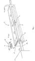
- Fig. 1 illustrates schematically a device for carrying out the inventive method
- Fig. 2 illustrates schematically parts of the Fig. 1 embodiment in larger scale.
- Fig. 1 illustrates a device 1 for forced curing of a glue joint in accordance with one preferred embodiment of the invention.
- the device 1 is described as being placed in the immediate vicinity of a finger jointing machine, not shown.
- the boards exiting from the machine are fed directly into the device 1.
- the boards 2 rest in the device 1 on a slide surface 3 and are advanced through said device solely by the propelling force exerted from the finger jointing machine.
- the joint As a glue joint 4 leaving the finger jointing machine enters the device 1, the joint is subjected to a high-frequency field generated between two electrode surfaces connected to a high-frequency generator, not shown.
- the high-frequency field is caused to accompany the glue joint as it moves through the device, along a specific distance therein. All of the glue joints of the combined board unit will have been completely cured when the unit leaves the device 1, therewith enabling the unit to be safely worked.
- the high-frequency field is generated between two generally parallel electrode surfaces that are disposed on respective sides of the glue joint to be heated.
- the slide surface 3 is made of aluminum and connected to a first pole of the two poles of the HF-generator, wherein the slide surface 3 forms one, the lower, of said two electrode surfaces.
- the slide surface 3 may also be provided with a thin friction reducing layer, for instance a Teflon® or like layer, so as to reduce friction, facilitate movement of the boards through the device, and reduce deposits of surplus glue from the glue joints.
- the other electrode surface 5, the upper surface, is comprised of an aluminium plate which is movable in the direction of board movement and which is placed over the glue joint so as to at least cover said joint.
- the upper electrode surface 5 is connected to the other pole of the HF-generator in a manner described below, therewith to generate an HF-field between the upper and the lower electrode surfaces 5 and 3 respectively.
- the upper, movable electrode surface 5 is thus able to follow the glue joint as it moves over the slide surface 3, therewith producing an HF-field which accompanies the glue joint.
- the upper electrode surface 5 is carried by an electrode carriage 6.
- the electrode carriage is arranged to move along a defining or delimiting surface 7 provided above and parallel with the slide surface 3 and in line with said surface.
- the carriage 6 is provided with pressure spring means 8 which function to press the electrode surface 5 against the glued boards or planks, such that the electrode surface will overlap the glue joint.
- the electrode surface may be provided with appropriate engagement means, e.g. studs, serrations, hooks or like devices, either on the electrode surface or in the immediate vicinity thereof.
- the defining surface 7 is made of an electrically conductive material and is connected to the HF-generator. Consequently, the electrode carriage 6 is able to transmit HF-voltage from the defining surface 7 to the electrode surface 5 directly, with the aid of a slip shoe or capacitively with the aid of an electrode plate 9 whose surface area is substantially larger than the electrode surface 5 and which is held at a relatively small distance from the defining surface 7.
- the carriage can be returned in any suitable way, for instance by means of a conveyor path, belt conveyor, handling arm or like carriage return means.
- Identification of an arriving glue joint is preferably achieved with the aid of an optical sensor of known design which will indicate when a glue joint is correctly positioned for receiving an electrode surface.
- An electrode carriage 6 can be positioned between the defining surface 7 and the boards or planks 2 in several different ways.
- the carriage may be suspended from a vertically movable carrier part which in a lower position forms an extension of the defining surface and which in its upper position is able to receive a further electrode carriage from a line of carriages, wherein infeed to the carrier part can take place with free passage between the electrode surface and the boards.
- the movable carrier part is pressed down to the same level as the defining surface, wherewith the spring means 8 on the electrode carriage is compressed and the electrode carriage therewith becomes active in the manner described above.
- the electrode carriage can be brought to an active position with the aid of an infeed ramp and a push-in means, wherewith the spring means 8 on the electrode carriage will be successively compressed as the carriage is fed in between an upwardly angled initial part, or extension, of the defining surface and the boards at the speed at which the boards are advanced, or with the aid of a funnel-shaped infeed part.
- the electrode carriage may advantageously be given a shear-elastic property between that part of the carriage which lies against the glue joint (the electrode surface) and that part which lies against the defining surface 7, wherein at least a part of the mass of the electrode carriage will be given a longer acceleration path, i.e. slower acceleration, than the electrode surface 5, said electrode surface preferably engaging the objects instantaneously and assuming the speed of said objects.
- the shear-elastic property can be achieved by causing the spring means also to spring in the shear direction.
- the spring means 8 may have the form of coil springs, leaf springs, soft elastic material with resilient properties, etc.
- each of the electrode surface 3 and the defining surface 7 can be connected to a respective broad rail along the full extent of their respective lengths.
- the rails are spaced a small distance apart on one side of the lower electrode surface 3 and the defining surface 7.
- the lower electrode surface 3 can be connected to a screening box or a casing 10 made of electrically conductive material, and the broad plate which includes the defining surface 7 placed at a very small distance beneath the sealing of the casing 10, as shown schematically in Fig. 2.
- very small distance or relatively small distance is meant here a small distance in relation to the distance between the slide surface 3 and the defining surface 7.
- the electrode means forming the local, joint-accompanying HF-field may be given different configurations in accordance with the application concerned.
- two electrode surfaces having a size such as to cover at least the glue joint may be placed on mutually opposite sides of the glue joint and caused to accompany the glue joint as it moves.
- the electrode surfaces may be carried by carrier means which can be moved in the movement direction of the glue joint, e.g. by arms of a scissor-like or tongs-like device connected to an HF-generator.
- the electrode surfaces are caused to leave the glue joint, by parting the arms of the scissor-like or tongs-like devices, therewith to return the electrode means to their original positions to await a further glue joint.
- the aluminium in the electrode surfaces and in other electrically conductive components can be replaced with other electrically conductive materials, such as metal sheet, steel, copper or the like.
- the friction-reducing and adhesion-reducing materials mentioned in the aforegoing can also be replaced with other materials having similar properties.
Landscapes
- Life Sciences & Earth Sciences (AREA)
- Engineering & Computer Science (AREA)
- Wood Science & Technology (AREA)
- Forests & Forestry (AREA)
- Mechanical Engineering (AREA)
- Manufacturing & Machinery (AREA)
- Lining Or Joining Of Plastics Or The Like (AREA)
- Coating Apparatus (AREA)
- Adhesives Or Adhesive Processes (AREA)
Claims (6)
- Procédé permettant de durcir des assemblages par collage entre des objets (2) lorsque lesdits objets se déplacent, dans lequel les assemblages par collage sont durcis dans un champ électrique haute-fréquence (HF) généré entre deux surfaces d'électrodes (3, 5) disposées sur des côtés opposés respectifs des objets assemblés mutuellement et raccordées à un générateur haute fréquence, caractérisé en ce que l'on amène un champ HF sensiblement limité audit assemblage par collage (4) à accompagner ledit assemblage par collage sur une distance spécifique suffisante pour réaliser le durcissement de la colle dans ledit assemblage par collage en ce que, l'on déplace les objets (2) le long d'une surface d'électrode allongée fixe (3) qui est constituée d'une desdites deux surfaces d'électrodes, et en ce que l'on amène une surface d'électrode mobile (5), constituée de l'autre desdites deux surfaces d'électrodes, et qui recouvre au moins ledit assemblage par collage, à accompagner l'assemblage par collage au fur et à mesure qu'il se déplace.
- Procédé selon la revendication 1, caractérisé en ce qu'on met la surface d'électrode mobile en butée contre l'assemblage par collage.
- Procédé selon l'une quelconque des revendications précédentes, caractérisé par des étapes consistant à identifier la position d'un assemblage par collage qui arrive, à appliquer à l'assemblage par collage une surface d'électrode mobile qui recouvre au moins l'assemblage par collage, à retirer la surface d'électrode mobile de l'assemblage par collage chauffé une fois que ladite surface d'électrode s'est déplacée sur une distance spécifique ; et à faire revenir ladite surface d'électrode mobile vers une ligne ou file de ces surfaces.
- Appareil permettant de durcir des assemblages par collage (4) entre des objets (2) au cours du déplacement desdits objets, dans lequel les objets sont collés bout à bout et dans lequel les assemblages par collage sont durcis dans un champ électrique haute fréquence généré entre deux surfaces d'électrodes (3, 5) déposées sur les surfaces opposées respectives des objets (2) reliés ensemble et raccordés à un générateur haute fréquence, caractérisé en ce qu'une première (3) desdites deux surfaces d'électrodes est fixe et allongée et présente une longueur suffisante pour réaliser le durcissement d'un assemblage par collage se déplaçant le long de ladite surface d'électrode ; et en ce que la deuxième (5) desdites surfaces d'électrodes peut se déplacer dans le sens du déplacement de l'assemblage par collage et présente une surface qui recouvre au moins l'assemblage par collage.
- Appareil selon la revendication 4, caractérisé en ce que l'appareil comprend une surface de glissement (3) sur laquelle les objets collés mutuellement peuvent glisser au travers de l'appareil ; et en ce que la surface de glissement comprend ladite surface d'électrode allongée, fixe.
- Appareil selon la revendication 4 ou la revendication 5, caractérisé en ce que la surface d'électrode mobile (5) est entraínée par des moyens porteurs (6) qui, quand ils se trouvent dans une position active, sont capables de se déplacer le long d'une surface de définition (7) disposée au-dessus, parallèlement à et alignée avec ladite surface de glissement (3) ; et en ce que les moyens porteurs (6) comprennent des moyens formant ressort qui agissent pour mettre la surface d'électrode mobile en butée contre l'assemblage par collage (4).
Applications Claiming Priority (3)
| Application Number | Priority Date | Filing Date | Title |
|---|---|---|---|
| SE9500801A SE9500801D0 (sv) | 1995-03-06 | 1995-03-06 | Förfarande för upphettning av lim samt anordning för genomförande av förfarandet |
| SE9500801 | 1995-03-06 | ||
| PCT/SE1996/000236 WO1996027482A1 (fr) | 1995-03-06 | 1996-02-21 | Procede et dispositif permettant de chauffer des assemblages par collage |
Publications (2)
| Publication Number | Publication Date |
|---|---|
| EP1017548A1 EP1017548A1 (fr) | 2000-07-12 |
| EP1017548B1 true EP1017548B1 (fr) | 2002-10-23 |
Family
ID=20397452
Family Applications (1)
| Application Number | Title | Priority Date | Filing Date |
|---|---|---|---|
| EP96906126A Expired - Lifetime EP1017548B1 (fr) | 1995-03-06 | 1996-02-21 | Procede et dispositif permettant de chauffer des assemblages par collage |
Country Status (7)
| Country | Link |
|---|---|
| EP (1) | EP1017548B1 (fr) |
| AU (1) | AU4959996A (fr) |
| DE (1) | DE69624518T2 (fr) |
| DK (1) | DK1017548T3 (fr) |
| FI (1) | FI974146A0 (fr) |
| SE (1) | SE9500801D0 (fr) |
| WO (1) | WO1996027482A1 (fr) |
Families Citing this family (3)
| Publication number | Priority date | Publication date | Assignee | Title |
|---|---|---|---|---|
| DE19737593C1 (de) * | 1997-08-28 | 1999-03-04 | Kuper Heinrich Gmbh Co Kg | Verfahren und Vorrichtung zum Verkleben von Furnierstreifen |
| WO2002074525A1 (fr) * | 2001-03-21 | 2002-09-26 | C.G. Di Cattelan Gianni & C. Snc | Presse continue, destinee en particulier a la fabrication de produits a parties jointes et adhesif synthetique associe |
| CN113751282B (zh) * | 2021-08-30 | 2022-09-06 | 江苏康迅数控装备科技有限公司 | 一种板材封边机用上置熔胶的涂胶装置 |
Family Cites Families (3)
| Publication number | Priority date | Publication date | Assignee | Title |
|---|---|---|---|---|
| FR2077902A1 (en) * | 1970-02-16 | 1971-11-05 | Dubost Gerard | Wood laminates mfre - as continuous straight or curved profiles without overstraining any plies |
| SE364662B (fr) * | 1971-01-25 | 1974-03-04 | N Alenius | |
| DK127846B (da) * | 1972-01-20 | 1974-01-21 | Obel Pedersen Ib | Fremgangsmåde ved sammenlimning af genstande samt apparat til fremgangsmåden udøvelse. |
-
1995
- 1995-03-06 SE SE9500801A patent/SE9500801D0/xx unknown
-
1996
- 1996-02-21 EP EP96906126A patent/EP1017548B1/fr not_active Expired - Lifetime
- 1996-02-21 DK DK96906126T patent/DK1017548T3/da active
- 1996-02-21 WO PCT/SE1996/000236 patent/WO1996027482A1/fr active IP Right Grant
- 1996-02-21 DE DE69624518T patent/DE69624518T2/de not_active Expired - Fee Related
- 1996-02-21 AU AU49599/96A patent/AU4959996A/en not_active Abandoned
-
1997
- 1997-11-05 FI FI974146A patent/FI974146A0/fi not_active IP Right Cessation
Also Published As
| Publication number | Publication date |
|---|---|
| DK1017548T3 (da) | 2003-02-24 |
| FI974146A (fi) | 1997-11-05 |
| DE69624518T2 (de) | 2003-06-18 |
| SE9500801D0 (sv) | 1995-03-06 |
| EP1017548A1 (fr) | 2000-07-12 |
| DE69624518D1 (de) | 2002-11-28 |
| WO1996027482A1 (fr) | 1996-09-12 |
| AU4959996A (en) | 1996-09-23 |
| FI974146A0 (fi) | 1997-11-05 |
Similar Documents
| Publication | Publication Date | Title |
|---|---|---|
| CA2325374C (fr) | Systeme et procede pour fabriquer des produits en bois comprime | |
| US7067035B2 (en) | Microwave preheat press assembly | |
| CA2204569A1 (fr) | Procede et ensemble d'appareil pour l'assemblage contenu et le collage de panneaux vernis afin de former des produits lamines | |
| EP0376918A2 (fr) | Méthode et dispositif pour produire des lamelles de bois à partir de bois de charpente | |
| EP1017548B1 (fr) | Procede et dispositif permettant de chauffer des assemblages par collage | |
| US4865881A (en) | Apparatus and process for making locking slide nuts | |
| US6056841A (en) | Method and apparatus for joining veneer pieces with lap joint having square cut edges and reduced thickness | |
| US5137066A (en) | Dovetail jointing press | |
| JP2875313B2 (ja) | 挽き材から薄板を製造する方法及び装置 | |
| MY134514A (en) | Joining method and apparatus of single veneer piece | |
| JP2020530398A5 (fr) | ||
| US3021248A (en) | Radio-frequency edge-gluing process | |
| US4681523A (en) | Conveyor for particleboard-making apparatus | |
| CA2261422A1 (fr) | Bois de placage composite | |
| CN109848533B (zh) | 全自动配件点焊设备 | |
| CA1259896A (fr) | Fabrication d'une poutre lamellee-collee a partir de bois deroule | |
| US3247042A (en) | Apparatus and method for manufacturing laminar materials joined together with wet adhesive webs | |
| CN110815435B (zh) | 一种木工移动接料和切料的方法 | |
| US5658382A (en) | Arrangement for painting an extended object continuously in its longitudinal direction | |
| US3722563A (en) | Method of mass-producing skis and an apparatus therefor | |
| DE59302174D1 (de) | Verfahren und Vorrichtung zum Richten von Holzlamellen | |
| US3524785A (en) | Apparatus for jointing timber sections | |
| AU660734B2 (en) | An arrangement for painting an extended object moving continuously in its longitudinal direction | |
| US4419557A (en) | Method and apparatus for welding metal parts coated with a thermoplastic | |
| US5445702A (en) | Apparatus for producing laminate boards |
Legal Events
| Date | Code | Title | Description |
|---|---|---|---|
| PUAI | Public reference made under article 153(3) epc to a published international application that has entered the european phase |
Free format text: ORIGINAL CODE: 0009012 |
|
| 17P | Request for examination filed |
Effective date: 19971006 |
|
| AK | Designated contracting states |
Kind code of ref document: A1 Designated state(s): DE DK SE |
|
| GRAG | Despatch of communication of intention to grant |
Free format text: ORIGINAL CODE: EPIDOS AGRA |
|
| 17Q | First examination report despatched |
Effective date: 20020205 |
|
| GRAG | Despatch of communication of intention to grant |
Free format text: ORIGINAL CODE: EPIDOS AGRA |
|
| GRAH | Despatch of communication of intention to grant a patent |
Free format text: ORIGINAL CODE: EPIDOS IGRA |
|
| GRAH | Despatch of communication of intention to grant a patent |
Free format text: ORIGINAL CODE: EPIDOS IGRA |
|
| GRAA | (expected) grant |
Free format text: ORIGINAL CODE: 0009210 |
|
| AK | Designated contracting states |
Kind code of ref document: B1 Designated state(s): DE DK SE |
|
| REF | Corresponds to: |
Ref document number: 69624518 Country of ref document: DE Date of ref document: 20021128 |
|
| REG | Reference to a national code |
Ref country code: DK Ref legal event code: T3 |
|
| PLBE | No opposition filed within time limit |
Free format text: ORIGINAL CODE: 0009261 |
|
| STAA | Information on the status of an ep patent application or granted ep patent |
Free format text: STATUS: NO OPPOSITION FILED WITHIN TIME LIMIT |
|
| 26N | No opposition filed |
Effective date: 20030724 |
|
| PGFP | Annual fee paid to national office [announced via postgrant information from national office to epo] |
Ref country code: DK Payment date: 20040123 Year of fee payment: 9 |
|
| PGFP | Annual fee paid to national office [announced via postgrant information from national office to epo] |
Ref country code: DE Payment date: 20040225 Year of fee payment: 9 |
|
| PGFP | Annual fee paid to national office [announced via postgrant information from national office to epo] |
Ref country code: SE Payment date: 20040227 Year of fee payment: 9 |
|
| PG25 | Lapsed in a contracting state [announced via postgrant information from national office to epo] |
Ref country code: SE Free format text: LAPSE BECAUSE OF NON-PAYMENT OF DUE FEES Effective date: 20050222 |
|
| PG25 | Lapsed in a contracting state [announced via postgrant information from national office to epo] |
Ref country code: DK Free format text: LAPSE BECAUSE OF NON-PAYMENT OF DUE FEES Effective date: 20050228 |
|
| PG25 | Lapsed in a contracting state [announced via postgrant information from national office to epo] |
Ref country code: DE Free format text: LAPSE BECAUSE OF NON-PAYMENT OF DUE FEES Effective date: 20050901 |
|
| REG | Reference to a national code |
Ref country code: DK Ref legal event code: EBP |
|
| EUG | Se: european patent has lapsed |