EP1017034A2 - Optischer Rauchmelder nach dem Extinktionsprinzip und Verfahren zur Kompensation von dessen Temperaturdrift - Google Patents
Optischer Rauchmelder nach dem Extinktionsprinzip und Verfahren zur Kompensation von dessen Temperaturdrift Download PDFInfo
- Publication number
- EP1017034A2 EP1017034A2 EP99117502A EP99117502A EP1017034A2 EP 1017034 A2 EP1017034 A2 EP 1017034A2 EP 99117502 A EP99117502 A EP 99117502A EP 99117502 A EP99117502 A EP 99117502A EP 1017034 A2 EP1017034 A2 EP 1017034A2
- Authority
- EP
- European Patent Office
- Prior art keywords
- light source
- smoke detector
- detector according
- measuring
- temperature drift
- Prior art date
- Legal status (The legal status is an assumption and is not a legal conclusion. Google has not performed a legal analysis and makes no representation as to the accuracy of the status listed.)
- Granted
Links
Images

Classifications
-
- G—PHYSICS
- G08—SIGNALLING
- G08B—SIGNALLING SYSTEMS, e.g. PERSONAL CALLING SYSTEMS; ORDER TELEGRAPHS; ALARM SYSTEMS
- G08B17/00—Fire alarms; Alarms responsive to explosion
- G08B17/10—Actuation by presence of smoke or gases, e.g. automatic alarm devices for analysing flowing fluid materials by the use of optical means
- G08B17/103—Actuation by presence of smoke or gases, e.g. automatic alarm devices for analysing flowing fluid materials by the use of optical means using a light emitting and receiving device
-
- G—PHYSICS
- G08—SIGNALLING
- G08B—SIGNALLING SYSTEMS, e.g. PERSONAL CALLING SYSTEMS; ORDER TELEGRAPHS; ALARM SYSTEMS
- G08B17/00—Fire alarms; Alarms responsive to explosion
- G08B17/10—Actuation by presence of smoke or gases, e.g. automatic alarm devices for analysing flowing fluid materials by the use of optical means
- G08B17/11—Actuation by presence of smoke or gases, e.g. automatic alarm devices for analysing flowing fluid materials by the use of optical means using an ionisation chamber for detecting smoke or gas
- G08B17/113—Constructional details
Definitions
- the present invention relates to an optical smoke detector based on the extinction principle, with an optical bridge, which is a light source, a measuring and a reference path and has a measuring and a reference receiver, and with an evaluation circuit.
- the extinction measurement method uses a beam of light through the ambient air and thus any measuring section accessible to smoke and through the section not accessible to the smoke Reference route is sent and the two received signals are sent together compared. Because both the light scattering on the smoke particles and the absorption by this contributes to the extinction and the light is scattered by light particles and dark particles is absorbed, the absorbance measurement method has a relatively uniform sensitivity on different smoke particles and is therefore used to detect smoldering fires (light particles) and from open fires (dark particles) are equally suitable.
- This temperature dependency is due to the fact that the optical elements provided in the optical bridge are next to the light source and the receivers, primarily lenses and mirrors, are temperature sensitive.
- the optical bridge contains that described in EP-A-0 578 189 Transmitted light detector waveguides and lenses and that described in EP-A-0 740 146 Transmitted light detector a plurality of parabolic mirrors made of injection molded plastic.
- the known point extinction or transmitted light detectors are intended to this effect be improved that the optical bridge as stable as possible and in particular as possible is not very sensitive to temperature.
- optical bridge next to the Light source and the measuring and the reference receiver as the only optical elements two has perforated screens arranged in front of the light source.
- a first preferred embodiment of the detector according to the invention is characterized in that that the light source is arranged in a chamber containing an air reservoir.
- the surface of the chamber is preferably substantially larger than that of the light source.
- This embodiment has the advantage that because of the large surface of the chamber Smoke particles slowly diffusing into the chamber on the chamber wall and not only be deposited on the light source.
- a second preferred embodiment of the detector according to the invention is characterized in that that the measuring section has at least one web with a pinhole, which keeps out penetrating, disturbing extraneous light and the radiation of the light source leaves unaffected.
- a third preferred embodiment of the detector according to the invention is characterized in that that the optical bridge has two end parts and a web connecting them, with the measuring section on one side of the web and the reference section on the other side is formed, and that in one end part the chamber with the light source and in the other chambers provided with the measuring receiver or the reference receiver are.
- This embodiment has the advantage that the optical bridge is manufactured in one piece and can be practically integrated into any detector housing.
- Another preferred embodiment of the detector according to the invention is characterized in that that the part of the optical bridge containing the reference path is on a Plate, preferably on the circuit board containing the evaluation circuit, attached and is laterally sealed by two side walls connecting the end parts and the web.
- the invention further relates to a method for compensating the temperature drift of the optical Bridge of the smoke detector mentioned.
- the method according to the invention is characterized in that that the temperature drift curve by heating the light source and determining the Detector signal is determined at different temperatures.
- the micro heater in the mounted detector is periodically activated and the current temperature drift curve is measured.
- the heater is used as part of the Manufacturing process of the detector or activated during a detector revision and the temperature drift curve measured.
- Another way of measuring the temperature drift curve is to switch the detector on Put into a furnace at the end of the manufacturing process and connected to a data bus, and to heat the furnace while measuring the temperature drift curve.
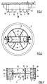
- a so-called detector insert which forms part of a point extinction or transmitted light detector, which also has a base and a detector hood (not shown).
- the detector insert is in a known manner for fastening in the base preferably mounted on the ceiling of a room to be monitored.
- the detector hood covering the detector insert and, if applicable, also the base is placed over the detector insert and locked with the base. Based on Fig. 1 located the ceiling with the base above and the dome facing the room to be monitored the detector hood below.
- the detector insert shown in FIGS. 1 and 2 consists of a base plate as shown 1, the top of an edge web 2 and below a cylindrical wall 3 and one inside the wall 3 has a rectangular recess 4, as well as an evaluation circuit containing circuit board 5 and an optical attached to the circuit board Bridge 6.
- the circuit board 5 is on the top of the base plate 1, within the edge web 2, fixed.
- the optical bridge 6 protrudes from the underside of the circuit board 1 down and is through the recess 4 is inserted.
- the optical bridge 6 is made of a highly thermally conductive material, preferably aluminum or Die-cast zinc, manufactured and consists of two end parts 7, 7 'and one connecting them Middle web 8.
- the end part 7 contains a chamber 9 with a light source 10 and the end part 7 ' contains two chambers 11 and 12 with a measuring and a reference receiver 13 and 14 respectively.
- a measuring section 15 Between the chamber 9 with the light source 10 and the chamber 11 with the measurement receiver 13 is a measuring section 15 and between the chamber 9 with the light source 10 and the chamber 12 with the reference receiver 14, a reference path 16 is formed.
- At least one web 17 with a perforated diaphragm 18 is arranged in the measuring section 15 from the side penetrating, disturbing extraneous light, but that emitted by the light source 18 Leaves usable light unaffected.
- the chamber 9 has one compared to the light source 10 relatively large surface area, so that smoke particles slowly diffusing into the chamber 9 deposit on the entire wall of the chamber and not only on the light source 10. As a result, the light source 10, if at all, only very slowly due to smoke or smoke Dust particles dirty.
- a web 17 'with a Pinhole 18 ' may be provided.
- the measuring section and the reference section 15 and 16 are designed such that the reference section 16 not accessible for smoke entering the detector from outside and in relation to it shielded and the measuring section 15 is freely accessible for such smoke.
- the shield the reference section 16 is through the central web 8, the two end parts 7 and 7 'and through two side walls 23 connecting the end parts 7 and 7 'and the central web 8. can the reference path 16 upwards to the printed circuit board 5 through an over the entire Length and width of the optical bridge 6 extending plate (not shown) may be covered.
- the light source 10 is by a light (possibly infrared radiation) emitting diode (LED or IRED), which sends light pulses into the measuring section 15 and the reference section 16.
- LED or IRED light emitting diode
- the measuring and reference sections 15 and 16 contain the light source 10 and the receiver 13, 14 as the only optical elements two in the beam path perforated diaphragms L, L 'of approximately 1 to 2 mm in diameter arranged after the light source 10. There is a temperature dependence of the diameter or the position of these pinholes difficult to imagine and would have no impact on the accuracy or stability of the detector.
- the measurement receiver 13 and the reference receiver 14 are identical photodiodes, which are due to a corresponding design of the measuring and reference sections 15 and 16, respectively receive the same amount of radiation from the light source 10. So that's through the radiation the light source 10 in the two receivers 13 and 14 triggered photo streams of the same size and the difference between these two photo streams remains zero until the optical properties the measuring section 15 due to external influences, for example by penetrating smoke particles, to be changed. Then the difference between the photocurrents is no longer zero but increases proportionally for cloudiness or extinction.
- the light source 10 is arranged on a plate-shaped carrier 19, which on the End face of the optical bridge 6 having chamber 9 is screwed on and the chamber 9 seals dust-tight.
- the corresponding electrical connections are from the carrier 19 Printed circuit board 5.
- the two receivers 13 and 14 are on a common plate-shaped Carrier 20 arranged, the on the chambers 11 and 12 containing the end face of the optical bridge 6 is screwed on. From the carrier 20 are the corresponding electrical Connections to the circuit board 5 out.
- On the underside of the base plate 1 is a cup-shaped, fine-meshed grid or network 21 (Fig. 1) inserted, which the optical bridge 6 against protects against the entry of insects or larger smoke or dirt particles.
- Another potential source of interference is external light entering the measuring section 15 from the outside. This is through the aperture 18, the cylindrical wall 3 and through blocked from this wall radially inward, against the optical bridge 6, protruding shutters 22.
- the optical bridge 6 has two potential problem points, which essentially by the temperature dependence of the sensitivity of the photodiodes 13 and 14 and due to the temperature dependence of the emission of the LED forming the light source 10 are.
- the temperature dependence of the sensitivity of the photodiodes is approximately 100 to 1000 ppm / ° C and that of the emission of the LED 10 about 4000 to 8000 ppm / ° C. Even if for the two photodiodes 13 and 14, a pair of adjacent ones on the silicon wafer Photodiode chips are used, the temperature coefficient cannot be excluded the sensitivity of the two photodiodes 13 and 14 are different, so that an optical bridge 6 adjusted at room temperature is at room temperature deviating temperatures would be out of balance.
- the temperature coefficient weak or slightly dependent on the emission direction. This also applies to bare LED chips, without bond wire across the chip, without epoxy covering and without Pressed glass lid.
- the reason for this dependence of the temperature coefficient of the emission lies in the temperature-dependent refractive index of the chip material, such as gallium arsenide, whose refractive index increases by about 0.23% between 20 ° and 50 ° C.
- the Light emerging from the chip is broken away from the solder with increasing temperature and the lobe of light, which is never completely vertical on the chip, widens slightly, causing the optical bridge 6 can also get out of balance.
- the temperature drift of the optical bridge is used to eliminate these possible interferences 6 measured and the temperature drift curve determined in this way is stored in a non-volatile memory element stored in the evaluation circuit. Then when evaluating the detector signal the temperature drift is computationally compensated.
- the measurement of the temperature drift can either periodically on the mounted detector in the field or as part of the manufacturing process or also for detector revisions.
- the temperature drift curve is preferably stored in an EEPROM of the detector.
- the measurement of the temperature of the optical bridge 6 is carried out by an arranged on the plate 19 NTC resistor (not shown).
- the outside temperature can also be measured so that the described one Transmitted light detectors can also be used to detect aerosol-free fires.
- a further NTC resistor is provided in an area of the top of the detector hood that is easily accessible to ambient air, the output signal of which is compared with a temperature limit value, an alarm being triggered if this limit value is exceeded.
- the design of the detector hood and the arrangement of the NTC resistor for measuring the temperature of the ambient air and the evaluation of its signal are similar to the optical-thermal smoke detector PolyRex of the AlgoRex fire detection system mentioned above .
- the temperature drift curve as part of the manufacturing process or for detector revisions To be able to measure, the aluminum part carrying the optical bridge 6 with a small Provide heating. This heater is used at the end of the manufacturing process or for detector revisions activated and measurements are made at different temperatures, the results, which represent the temperature drift curve, in the EEPROM of the Be filed.
- the heater can be, for example, a power transistor, a PTC heating element, a thick film resistor or a thin film resistor on ceramic.
- the temperature drift curve can also be measured as part of the manufacturing process be that the detector, which in this case does not require any special heating, on End of the manufacturing process in an oven and a suitable temperature cycle from for example 20 ° to 60 ° C and the temperature drift curve in the EEPROM of the Filers.
- Light source 10 used.
- An example of such a light source is shown in FIG schematic view shown with cut open housing. Contains as shown the LED 10 forming the light source essentially one surrounded by a housing wall 24 Base or base 25 which carries the chip 26 of the LED. Between the chip 26 and a self-regulating PTC heating element 27 is provided in the base 25.
- the LED 10 has three Connection wires 28, 29 and 30, wherein the connection 28 with the chip 26, the chip 26 bearing upper surface of the PTC heating element 27 with the connection 30 and that on the Base 25 overlying lower surface of the heating element 27 is bonded to the connection 29.
- bonding is understood to mean the establishment of electrical connections within of semiconductor elements through thin gold wires.
- the PTC heating element 27 consists, for example, of doped barium titanate, the contact areas are each coated with gold, silver or aluminum.
- the housing is at the top completed by a glass lid 31. If necessary, can be between the PTC heating element 27 and the base 25 a thermal insulation, for example a glass pane 32, be provided.
- the heating element 27 is periodically, for example once a day, on different Temperatures heated and the temperature drift curve is measured and in EEPROM of the detector stored. Since it cannot be ruled out that it is in the measurement the temperature drift curve has just burned, is used to compensate for the temperature drift Detector signal always uses the temperature drift curve of the previous day.
- the PTC heating element 27 instead of the PTC heating element 27, another micro heater can also be used within the housing the LED 26 can be used, for example a transistor chip or a platinum wire heater. Practical investigations have shown that a platinum wire micro heater on the the same temperature drift curve leads as heating the entire light source 10 from the outside. This Method is very attractive because it adapts the detector to the detector life span changing component properties allowed. However, it presupposes that the two photodiodes 13, 14 (Fig. 3) form a matching pair. If not If so, the contribution of the photodiodes to the temperature drift of the detector signal must one of the two methods described in the manufacture of detectors can be determined.
- the natural temperature fluctuation can vary between Day and night are used to match the slope of the temperature drift curve Check section and adjust the temperature drift curve if necessary and in To issue an emergency report in the event of deviations that are too large.
Landscapes
- Chemical & Material Sciences (AREA)
- Analytical Chemistry (AREA)
- Business, Economics & Management (AREA)
- Emergency Management (AREA)
- Physics & Mathematics (AREA)
- General Physics & Mathematics (AREA)
- Investigating Or Analysing Materials By Optical Means (AREA)
- Fire-Detection Mechanisms (AREA)
Abstract
Description
- Fig. 1
- eine Seitenansicht des Meldereinsatzes eines erfindungsgemässen Melders,
- Fig. 2
- eine Ansicht in Richtung des Pfeiles II von Fig. 1,
- Fig. 3
- einen Längsschnitt durch die optische Brücke des Meldereinsatzes nach der Linie III-III von Fig. 2; und
- Fig. 4
- ein Detail der optischen Brücke von Fig. 3.
Claims (18)
- Optischer Rauchmelder nach dem Extinktionsprinzip, mit einer optischen Brücke (6), welche eine Lichtquelle (10), eine Mess- und eine Referenzstrecke (15 bzw. 16) und einen Mess- und einen Referenzempfänger (13 bzw. 14) aufweist, und mit einer Auswerteschaltung, dadurch gekennzeichnet, dass die optische Brücke (6) neben der Lichtquelle (10) und dem Mess- und dem Referenzempfänger (13 bzw. 14) als einzige optische Elemente zwei vor der Lichtquelle (10) angeordnete Lochblenden (L, L') aufweist.
- Rauchmelder nach Anspruch 1, dadurch gekennzeichnet, dass die Lichtquelle (10) in einer ein Luftreservoir enthaltenden Kammer (9) angeordnet ist.
- Rauchmelder nach Anspruch 2, dadurch gekennzeichnet, dass die Oberfläche der Kammer (9) wesentlich grösser ist als diejenige der Lichtquelle (10).
- Rauchmelder nach Anspruch 2 oder 3, dadurch gekennzeichnet, dass die Messstrecke (15) mindestens einen Steg (17) mit einer Lochblende (18) aufweist, welche seitlich eindringendes, störendes Fremdliche abhält und die Strahlung der Lichtquelle (10) unbeeinflusst lässt.
- Rauchmelder nach einem der Ansprüche 2 bis 4, dadurch gekennzeichnet, dass die optische Brücke (6) zwei Endteile (7, 7') und einen diese verbindenden Steg (8) aufweist, wobei an der einen Seite des Stegs (8) die Messstrecke (15) und an der anderen Seite die Referenzstrecke (16) gebildet ist, und dass in dem einen Endteil (7) die Kammer (9) mit der Lichtquelle (10) und in dem anderen (7') Kammern (11, 12) mit dem Messempfänger (13) beziehungsweise dem Referenzempfänger (14) vorgesehen sind.
- Rauchmelder nach Anspruch 5, dadurch gekennzeichnet, dass der die Referenzstrecke (16) enthaltende Teil der optischen Brücke (6) auf einer Platte, vorzugsweise auf der die Auswerteschaltung enthaltenden Leiterplatte (5), befestigt und seitlich durch zwei die Endteile (7, 7') und den Steg (8) verbindende Seitenwände (23) abgedichtet ist.
- Rauchmelder nach Anspruch 5 oder 6, dadurch gekennzeichnet, dass die die Lichtquelle (10) enthaltende Kammer (9) und die den Mess- und den Referenzempfänger (13 bzw. 14) enthaltenden Kammern (11 bzw. 12) nach aussen abgeschlossen sind.
- Rauchmelder nach Anspruch 7, dadurch gekennzeichnet, dass die genannten Kammern (10, 11, 12) je durch eine Platte (19, 20) abgeschlossen sind, welche als Träger der Lichtquelle (10) beziehungsweise des Mess- und des Referenzempfängers (13, 14) dient.
- Rauchmelder nach Anspruch 8, dadurch gekennzeichnet, dass auf einer der beiden Platten (19, 20), vorzugsweise auf der die Lichtquelle (10) tragenden, ein Mittel zur Messung der Temperatur der optischen Brücke (6) vorgesehen ist.
- Rauchmelder nach einem der Ansprüche 1 bis 9, dadurch gekennzeichnet, dass die optische Brücke aus einem gut wärmeleitenden Material, vorzugsweise aus Aluminium- oder Zinkdruckguss, besteht.
- Rauchmelder nach Anspruch 2, dadurch gekennzeichnet, dass die Auswerteschaltung ein nicht-flüchtiges Speicherelement enthält, in welchem die Temperaturdriftkurve der optischen Brücke (6) abgelegt ist, und dass Mittel zur rechnerischen Kompensation des Einflusses der Temperaturdriftkurve auf das Meldersignal vorgesehen sind.
- Rauchmelder nach Anspruch 11, dadurch gekennzeichnet, dass die Lichtquelle (10) durch eine ein Gehäuse (24) aufweisende Leuchtdiode gebildet ist, deren Chip (26) auf einer Mikroheizung (27) innerhalb des Gehäuses (24) montiert ist.
- Rauchmelder nach Anspruch 12, dadurch gekennzeichnet, dass die Mikroheizung (27) durch eine Platindrahtheizung oder ein PTC-Heizelement oder einen Transistorchip gebildet ist.
- Rauchmelder nach Anspruch 13, dadurch gekennzeichnet, dass zwischen der Mikroheizung (27) und dem Boden (25) des Gehäuses (24) eine thermische Isolierung (32) vorgesehen ist.
- Verfahren zur Kompensation der Temperaturdrift der optischen Brücke (6) des Rauchmelders nach Anspruch 1, dadurch gekennzeichnet, dass die Temperaturdriftkurve durch Heizen der Lichtquelle (8) und Bestimmung des Meldersignals bei verschiedenen Temperaturen ermittelt wird.
- Verfahren nach Anspruch 15, dadurch gekennzeichnet, dass bei einem Melder, dessen Lichtquelle (10) durch eine Leuchtdiode gebildet ist, welche einen mit einer Mikroheizung (27) heizbaren Chip (26) aufweist, die Mikroheizung (27) im montierten Melder vor Ort periodisch aktiviert und dabei die aktuelle Temperaturdriftkurve gemessen wird.
- Verfahren nach Anspruch 16, dadurch gekennzeichnet, dass bei einem Melder, dessen optische Brücke (6) auf einem mit einer Heizung versehenen Träger aus einem Material mit guter Wärmeleitfähigkeit montiert ist, die Heizung im Rahmen des Herstellungsprozesses des Melders oder bei einer Melderrevision aktiviert und dabei die Temperaturdriftkurve gemessen wird.
- Verfahren nach Anspruch 17, dadurch gekennzeichnet, dass der Melder am Ende des Herstellungsprozesses in einen Ofen gegeben und an einen Datenbus angeschlossen, und dass der Ofen geheizt und dabei die Temperaturdriftkurve gemessen wird.
Priority Applications (1)
| Application Number | Priority Date | Filing Date | Title |
|---|---|---|---|
| EP99117502A EP1017034B1 (de) | 1998-09-14 | 1999-09-04 | Optischer Rauchmelder nach dem Extinktionsprinzip und Verfahren zur Kompensation von dessen Temperaturdrift |
Applications Claiming Priority (5)
| Application Number | Priority Date | Filing Date | Title |
|---|---|---|---|
| EP98117368 | 1998-09-14 | ||
| EP98117368A EP0987663A1 (de) | 1998-09-14 | 1998-09-14 | Optischer Rauchmelder nach dem Extinktionsprinzip und Verfahren zur Kompensation von dessen Temperaturdrift |
| CH217298 | 1998-10-27 | ||
| CH217298 | 1998-10-27 | ||
| EP99117502A EP1017034B1 (de) | 1998-09-14 | 1999-09-04 | Optischer Rauchmelder nach dem Extinktionsprinzip und Verfahren zur Kompensation von dessen Temperaturdrift |
Publications (3)
| Publication Number | Publication Date |
|---|---|
| EP1017034A2 true EP1017034A2 (de) | 2000-07-05 |
| EP1017034A3 EP1017034A3 (de) | 2000-08-02 |
| EP1017034B1 EP1017034B1 (de) | 2003-08-27 |
Family
ID=27173502
Family Applications (1)
| Application Number | Title | Priority Date | Filing Date |
|---|---|---|---|
| EP99117502A Expired - Lifetime EP1017034B1 (de) | 1998-09-14 | 1999-09-04 | Optischer Rauchmelder nach dem Extinktionsprinzip und Verfahren zur Kompensation von dessen Temperaturdrift |
Country Status (1)
| Country | Link |
|---|---|
| EP (1) | EP1017034B1 (de) |
Cited By (3)
| Publication number | Priority date | Publication date | Assignee | Title |
|---|---|---|---|---|
| EP1349127A1 (de) * | 2002-03-28 | 2003-10-01 | Siemens Building Technologies AG | Optischer Rauchmelder nach dem Extinktionsprinzip und dessen Verwendung |
| EP1768074A1 (de) | 2005-09-21 | 2007-03-28 | Siemens Schweiz AG | Frühzeitige Detektion von Bränden |
| US11151851B1 (en) | 2020-05-22 | 2021-10-19 | Carrier Corporation | Trace heating base for heating detectors |
Family Cites Families (7)
| Publication number | Priority date | Publication date | Assignee | Title |
|---|---|---|---|---|
| CH546989A (de) * | 1972-12-06 | 1974-03-15 | Cerberus Ag | Verfahren und vorrichtung zur brandmeldung. |
| US4266220A (en) * | 1979-07-27 | 1981-05-05 | Malinowski William J | Self-calibrating smoke detector and method |
| DE3334545A1 (de) * | 1983-09-23 | 1985-04-04 | Siemens AG, 1000 Berlin und 8000 München | Optischer rauchmelder |
| JPS60168296A (ja) * | 1984-02-13 | 1985-08-31 | 株式会社日本自動車部品総合研究所 | 光電式煙感知器 |
| CH683464A5 (de) * | 1991-09-06 | 1994-03-15 | Cerberus Ag | Optischer Rauchmelder mit aktiver Ueberwachung. |
| DE4320873A1 (de) * | 1993-06-23 | 1995-01-05 | Hekatron Gmbh | Schaltungsanordnung für einen optischen Melder zur Umweltüberwachung und Anzeige eines Störmediums |
| GB2314618B (en) * | 1996-06-26 | 1999-12-29 | David Appleby | Smoke detector using light scatter and extinction |
-
1999
- 1999-09-04 EP EP99117502A patent/EP1017034B1/de not_active Expired - Lifetime
Cited By (3)
| Publication number | Priority date | Publication date | Assignee | Title |
|---|---|---|---|---|
| EP1349127A1 (de) * | 2002-03-28 | 2003-10-01 | Siemens Building Technologies AG | Optischer Rauchmelder nach dem Extinktionsprinzip und dessen Verwendung |
| EP1768074A1 (de) | 2005-09-21 | 2007-03-28 | Siemens Schweiz AG | Frühzeitige Detektion von Bränden |
| US11151851B1 (en) | 2020-05-22 | 2021-10-19 | Carrier Corporation | Trace heating base for heating detectors |
Also Published As
| Publication number | Publication date |
|---|---|
| EP1017034A3 (de) | 2000-08-02 |
| EP1017034B1 (de) | 2003-08-27 |
Similar Documents
| Publication | Publication Date | Title |
|---|---|---|
| EP1376504B1 (de) | Streulichtrauchmelder | |
| DE68928739T2 (de) | Detecteur d'humidite | |
| WO2004001694A1 (de) | Brandmelder | |
| DE3028252C2 (de) | ||
| EP0023354B1 (de) | Pyrodetektor | |
| CH675921A5 (de) | ||
| EP0987663A1 (de) | Optischer Rauchmelder nach dem Extinktionsprinzip und Verfahren zur Kompensation von dessen Temperaturdrift | |
| EP0878703A2 (de) | Kombinierter Gassensor zur Detektion von Gasen und Partikeln mit Betriebsverfahren und Verwendungen | |
| DE69934662T2 (de) | Ultraviolett-detektor | |
| EP2775465A1 (de) | Gefahrenmelder mit einem kontaktlos arbeitenden Wärmestrahlungssensor zur Ermittlung einer Umgebungstemperatur | |
| CH646262A5 (de) | Pyroelektrischer detektor. | |
| EP1017034B1 (de) | Optischer Rauchmelder nach dem Extinktionsprinzip und Verfahren zur Kompensation von dessen Temperaturdrift | |
| DE19835769C2 (de) | Optoelektronischer Gassensor auf der Basis von Optoden | |
| DE19804036A1 (de) | Sensorsystem und Multisensorsystem zur Erfassung von klimatischen Meßdaten sowie Verfahren zur Herstellung des Sensorsystems und des Multisensorsystems | |
| CA1042564A (en) | Ionization type smoke sensor | |
| DE2208904C3 (de) | Gerät zur Messung von Sichtwetten | |
| EP0105199B1 (de) | Strahlungsrauchmelder | |
| DE102005003657A1 (de) | Infrarotstrahlungsdetektor mit Infrarotstrahlunssensor und Gehäuse | |
| DE4244607A1 (de) | Thermoelektrischer Strahlungssensor, insbesondere für infrarotes und sichtbares Licht | |
| WO1992010819A1 (de) | Passiv-infrarot-bewegungsmelder | |
| DE3924250C2 (de) | ||
| EP1349127A1 (de) | Optischer Rauchmelder nach dem Extinktionsprinzip und dessen Verwendung | |
| EP3035012A2 (de) | Verfahren, halbleiterdetektor und detektoranordnung zur detektion von sonnenlicht | |
| DE112020004357T5 (de) | Durchflussmessgerät | |
| DE102024103527A1 (de) | Sensorvorrichtung mit kammerlosem Rauchmelder |
Legal Events
| Date | Code | Title | Description |
|---|---|---|---|
| PUAI | Public reference made under article 153(3) epc to a published international application that has entered the european phase |
Free format text: ORIGINAL CODE: 0009012 |
|
| PUAL | Search report despatched |
Free format text: ORIGINAL CODE: 0009013 |
|
| AK | Designated contracting states |
Kind code of ref document: A2 Designated state(s): AT BE CH CY DE DK ES FI FR GB GR IE IT LI LU MC NL PT SE |
|
| AX | Request for extension of the european patent |
Free format text: AL;LT;LV;MK;RO;SI |
|
| AK | Designated contracting states |
Kind code of ref document: A3 Designated state(s): AT BE CH CY DE DK ES FI FR GB GR IE IT LI LU MC NL PT SE |
|
| AX | Request for extension of the european patent |
Free format text: AL;LT;LV;MK;RO;SI |
|
| RAP1 | Party data changed (applicant data changed or rights of an application transferred) |
Owner name: SIEMENS BUILDING TECHNOLOGIES AG |
|
| 17P | Request for examination filed |
Effective date: 20010124 |
|
| AKX | Designation fees paid |
Free format text: AT BE CH CY DE DK ES FI FR GB GR IE IT LI LU MC NL PT SE |
|
| GRAH | Despatch of communication of intention to grant a patent |
Free format text: ORIGINAL CODE: EPIDOS IGRA |
|
| GRAH | Despatch of communication of intention to grant a patent |
Free format text: ORIGINAL CODE: EPIDOS IGRA |
|
| GRAA | (expected) grant |
Free format text: ORIGINAL CODE: 0009210 |
|
| AK | Designated contracting states |
Designated state(s): AT BE CH CY DE DK ES FI FR GB GR IE IT LI LU MC NL PT SE |
|
| PG25 | Lapsed in a contracting state [announced via postgrant information from national office to epo] |
Ref country code: NL Free format text: LAPSE BECAUSE OF FAILURE TO SUBMIT A TRANSLATION OF THE DESCRIPTION OR TO PAY THE FEE WITHIN THE PRESCRIBED TIME-LIMIT Effective date: 20030827 Ref country code: IT Free format text: LAPSE BECAUSE OF FAILURE TO SUBMIT A TRANSLATION OF THE DESCRIPTION OR TO PAY THE FEE WITHIN THE PRE;WARNING: LAPSES OF ITALIAN PATENTS WITH EFFECTIVE DATE BEFORE 2007 MAY HAVE OCCURRED AT ANY TIME BEFORE 2007. THE CORRECT EFFECTIVE DATE MAY BE DIFFERENT FROM THE ONE RECORDED.SCRIBED TIME-LIMIT Effective date: 20030827 Ref country code: IE Free format text: LAPSE BECAUSE OF FAILURE TO SUBMIT A TRANSLATION OF THE DESCRIPTION OR TO PAY THE FEE WITHIN THE PRESCRIBED TIME-LIMIT Effective date: 20030827 Ref country code: FI Free format text: LAPSE BECAUSE OF FAILURE TO SUBMIT A TRANSLATION OF THE DESCRIPTION OR TO PAY THE FEE WITHIN THE PRESCRIBED TIME-LIMIT Effective date: 20030827 |
|
| REG | Reference to a national code |
Ref country code: GB Ref legal event code: FG4D Free format text: NOT ENGLISH |
|
| REG | Reference to a national code |
Ref country code: CH Ref legal event code: EP |
|
| PG25 | Lapsed in a contracting state [announced via postgrant information from national office to epo] |
Ref country code: LU Free format text: LAPSE BECAUSE OF NON-PAYMENT OF DUE FEES Effective date: 20030904 Ref country code: CY Free format text: LAPSE BECAUSE OF FAILURE TO SUBMIT A TRANSLATION OF THE DESCRIPTION OR TO PAY THE FEE WITHIN THE PRESCRIBED TIME-LIMIT Effective date: 20030904 |
|
| PG25 | Lapsed in a contracting state [announced via postgrant information from national office to epo] |
Ref country code: MC Free format text: LAPSE BECAUSE OF NON-PAYMENT OF DUE FEES Effective date: 20030930 Ref country code: BE Free format text: LAPSE BECAUSE OF NON-PAYMENT OF DUE FEES Effective date: 20030930 |
|
| REG | Reference to a national code |
Ref country code: IE Ref legal event code: FG4D Free format text: GERMAN |
|
| REF | Corresponds to: |
Ref document number: 59906761 Country of ref document: DE Date of ref document: 20031002 Kind code of ref document: P |
|
| PG25 | Lapsed in a contracting state [announced via postgrant information from national office to epo] |
Ref country code: SE Free format text: LAPSE BECAUSE OF FAILURE TO SUBMIT A TRANSLATION OF THE DESCRIPTION OR TO PAY THE FEE WITHIN THE PRESCRIBED TIME-LIMIT Effective date: 20031127 Ref country code: GR Free format text: LAPSE BECAUSE OF FAILURE TO SUBMIT A TRANSLATION OF THE DESCRIPTION OR TO PAY THE FEE WITHIN THE PRESCRIBED TIME-LIMIT Effective date: 20031127 Ref country code: DK Free format text: LAPSE BECAUSE OF FAILURE TO SUBMIT A TRANSLATION OF THE DESCRIPTION OR TO PAY THE FEE WITHIN THE PRESCRIBED TIME-LIMIT Effective date: 20031127 |
|
| PG25 | Lapsed in a contracting state [announced via postgrant information from national office to epo] |
Ref country code: ES Free format text: LAPSE BECAUSE OF FAILURE TO SUBMIT A TRANSLATION OF THE DESCRIPTION OR TO PAY THE FEE WITHIN THE PRESCRIBED TIME-LIMIT Effective date: 20031208 |
|
| GBT | Gb: translation of ep patent filed (gb section 77(6)(a)/1977) |
Effective date: 20031113 |
|
| PG25 | Lapsed in a contracting state [announced via postgrant information from national office to epo] |
Ref country code: PT Free format text: LAPSE BECAUSE OF FAILURE TO SUBMIT A TRANSLATION OF THE DESCRIPTION OR TO PAY THE FEE WITHIN THE PRESCRIBED TIME-LIMIT Effective date: 20040127 |
|
| NLV1 | Nl: lapsed or annulled due to failure to fulfill the requirements of art. 29p and 29m of the patents act | ||
| BERE | Be: lapsed |
Owner name: *SIEMENS BUILDING TECHNOLOGIES A.G. Effective date: 20030930 |
|
| REG | Reference to a national code |
Ref country code: IE Ref legal event code: FD4D |
|
| ET | Fr: translation filed | ||
| PLBE | No opposition filed within time limit |
Free format text: ORIGINAL CODE: 0009261 |
|
| STAA | Information on the status of an ep patent application or granted ep patent |
Free format text: STATUS: NO OPPOSITION FILED WITHIN TIME LIMIT |
|
| 26N | No opposition filed |
Effective date: 20040528 |
|
| REG | Reference to a national code |
Ref country code: CH Ref legal event code: PFA Owner name: SIEMENS BUILDING TECHNOLOGIES AG C-IPR Free format text: SIEMENS BUILDING TECHNOLOGIES AG#BELLERIVESTRASSE 36#8034 ZUERICH (CH) -TRANSFER TO- SIEMENS BUILDING TECHNOLOGIES AG C-IPR#GUBELSTRASSE 22#6300 ZUG (CH) |
|
| PGFP | Annual fee paid to national office [announced via postgrant information from national office to epo] |
Ref country code: DE Payment date: 20071122 Year of fee payment: 9 |
|
| PGFP | Annual fee paid to national office [announced via postgrant information from national office to epo] |
Ref country code: CH Payment date: 20071211 Year of fee payment: 9 |
|
| REG | Reference to a national code |
Ref country code: FR Ref legal event code: TP Ref country code: FR Ref legal event code: CD |
|
| PGFP | Annual fee paid to national office [announced via postgrant information from national office to epo] |
Ref country code: FR Payment date: 20080918 Year of fee payment: 10 Ref country code: AT Payment date: 20080808 Year of fee payment: 10 |
|
| PGFP | Annual fee paid to national office [announced via postgrant information from national office to epo] |
Ref country code: GB Payment date: 20080911 Year of fee payment: 10 |
|
| REG | Reference to a national code |
Ref country code: CH Ref legal event code: PL |
|
| REG | Reference to a national code |
Ref country code: GB Ref legal event code: 732E Free format text: REGISTERED BETWEEN 20090514 AND 20090520 |
|
| PG25 | Lapsed in a contracting state [announced via postgrant information from national office to epo] |
Ref country code: DE Free format text: LAPSE BECAUSE OF NON-PAYMENT OF DUE FEES Effective date: 20090401 |
|
| PG25 | Lapsed in a contracting state [announced via postgrant information from national office to epo] |
Ref country code: LI Free format text: LAPSE BECAUSE OF NON-PAYMENT OF DUE FEES Effective date: 20080930 Ref country code: CH Free format text: LAPSE BECAUSE OF NON-PAYMENT OF DUE FEES Effective date: 20080930 |
|
| GBPC | Gb: european patent ceased through non-payment of renewal fee |
Effective date: 20090904 |
|
| REG | Reference to a national code |
Ref country code: FR Ref legal event code: ST Effective date: 20100531 |
|
| PG25 | Lapsed in a contracting state [announced via postgrant information from national office to epo] |
Ref country code: AT Free format text: LAPSE BECAUSE OF NON-PAYMENT OF DUE FEES Effective date: 20090904 |
|
| PG25 | Lapsed in a contracting state [announced via postgrant information from national office to epo] |
Ref country code: FR Free format text: LAPSE BECAUSE OF NON-PAYMENT OF DUE FEES Effective date: 20090930 |
|
| PG25 | Lapsed in a contracting state [announced via postgrant information from national office to epo] |
Ref country code: GB Free format text: LAPSE BECAUSE OF NON-PAYMENT OF DUE FEES Effective date: 20090904 |