EP1016102B1 - Power transformer/inductor - Google Patents
Power transformer/inductor Download PDFInfo
- Publication number
- EP1016102B1 EP1016102B1 EP98902350A EP98902350A EP1016102B1 EP 1016102 B1 EP1016102 B1 EP 1016102B1 EP 98902350 A EP98902350 A EP 98902350A EP 98902350 A EP98902350 A EP 98902350A EP 1016102 B1 EP1016102 B1 EP 1016102B1
- Authority
- EP
- European Patent Office
- Prior art keywords
- power transformer
- winding
- inductor according
- earthing
- inductor
- Prior art date
- Legal status (The legal status is an assumption and is not a legal conclusion. Google has not performed a legal analysis and makes no representation as to the accuracy of the status listed.)
- Expired - Lifetime
Links
Images


Classifications
-
- H—ELECTRICITY
- H01—ELECTRIC ELEMENTS
- H01F—MAGNETS; INDUCTANCES; TRANSFORMERS; SELECTION OF MATERIALS FOR THEIR MAGNETIC PROPERTIES
- H01F27/00—Details of transformers or inductances, in general
- H01F27/34—Special means for preventing or reducing unwanted electric or magnetic effects, e.g. no-load losses, reactive currents, harmonics, oscillations, leakage fields
-
- H—ELECTRICITY
- H01—ELECTRIC ELEMENTS
- H01F—MAGNETS; INDUCTANCES; TRANSFORMERS; SELECTION OF MATERIALS FOR THEIR MAGNETIC PROPERTIES
- H01F27/00—Details of transformers or inductances, in general
- H01F27/28—Coils; Windings; Conductive connections
- H01F27/288—Shielding
-
- H—ELECTRICITY
- H01—ELECTRIC ELEMENTS
- H01F—MAGNETS; INDUCTANCES; TRANSFORMERS; SELECTION OF MATERIALS FOR THEIR MAGNETIC PROPERTIES
- H01F27/00—Details of transformers or inductances, in general
- H01F27/28—Coils; Windings; Conductive connections
- H01F27/2823—Wires
- H01F27/2828—Construction of conductive connections, of leads
Definitions
- the present invention relates to a power transformer/inductor.
- transformers In all transmission and distribution of electric energy transformers are used for enabling exchange between two or more electric systems normally having different voltage levels. Transformers are available for powers from the VA region to the 1000 MVA region. The voltage range has a spectrum of up to the highest transmission voltages used today. Electro-magnetic induction is used for energy transmission between electric systems.
- Inductors are also an essential component in the transmission of electric energy in for example phase compensation and filtering.
- the transformer/inductor related to the present invention belongs to the so-called power transformers/inductors having rated outputs from several hundred kVA to in excess of 1000 MVA and rated voltages of from 3-4 kV to very high transmission voltages
- the main task of a power transformer is to enable the exchange of electric energy, between two or more electric systems of mostly differing voltages with the same frequency.
- a conventional power transformer/inductor comprises a transformer core, referred to below as core, formed of laminated commonly oriented sheet, normally of silicon iron.
- the core is composed of a number of core legs connected by yokes.
- a number of windings are provided around the core legs normally referred to as primary, secondary and regulating winding. In power transformers these windings are practically always arranged in concentric configuration and distributed along the length of the core leg.
- the core may consist of conventional magnetizable materials such as said oriented sheet and other magnetizable materials such as ferrites, amorphous material, wire strands or metal tape.
- the magnetizable core is, as known, not necessary in inductors
- the above-mentioned windings constitute one or several coils connected in series, the coils of which having a number of turns connected in series.
- the turns of a single coil normally make up a geometric, continuous unit which is physically separated from the remaining coils
- a conductor is known through US 5 036 165 , in which the insulation is provided with an inner and an outer layer of semiconducting pyrolized glassfiber. It is also known to provide conductors in a dynamo-electric machine with such an insulation, as described in US 5 066 881 for instance, where a semiconducting pyrolized glassfiber layer is in contact with the two parallel rods forming the conductor, and the insulation in the stator slots is surrounded by an outer layer of semiconducting pyrolized glassfiber.
- the pyrolized glassfiber material is described as suitable since it retains its resistivity even after the impregnation treatment.
- the insulation system on the inside of a coil/winding and between coils/windings and remaining metal parts is normally in the form of a solid- or varnish based insulation closest to the conducting element and on the outside thereof the insulation system is in the form of a solid cellulose insulation, a fluid insulation, and possibly also an insulation in the form of gas.
- Windings with insulation and possible bulky parts represent in this way large volumes that will be subjected to high electric field strengths occurring in and around the active electric magnetic parts belonging to transformers.
- a detailed knowledge of the properties of insulation material is required in order to predetermine the dielectric field strengths which arise and to attain a dimensioning such that there is a minimal risk of electrical discharge. It is important to achieve a surrounding environment which does not change or reduce the insulation properties.
- Today's predominant outer insulation system for conventional high voltage power transformers/inductors consists of cellulose material as the solid insulation and transformer oil as the fluid insulation.
- Transformer oil is based on so-called mineral oil.
- the tank surrounding the transformer must be constructed in such a way that it is able to withstand full vacuum since the process requires that all the gas be pumped out to almost absolute vacuum which involves extra material consumption and manufacturing time.
- the power transformer/ inductor comprises at least one winding in most cases arranged around a magnetizable core which may be of different geometries.
- the term "windings" will be referred to below in order to simplify the following specification.
- the windings are composed of a high voltage cable with solid insulation.
- the cables have at least one centrally situated electric conductor.
- the second semi-conducting layer must be directly earthed in or in the vicinity of both ends of the cable so that the electric stress which arises, both during normal operating voltage and during transient progress, will primarily load only the solid insulation of the cable.
- the semi-conducting layer and these direct earthings form together a closed circuit in which a current is induced during operation.
- the resistivity of the layer must be high enough so that resistive losses arising in the layer are negligible.
- a capacitive current is to flow into the layer through both directly earthed ends of the cable. If the resistivity of the layer is too great, the capacitive current will become so limited that the potential in parts of the layer, during a period of alternating stress, may differ to such an extent from earth potential that regions of the power transformer/inductor other than the solid insulation of the windings will be subjected to electric stress.
- This one point earthing per turn of the outer layer is performed in such a way that the earth points rest on a generatrix to a winding and that points along the axial length of the winding are electrically directly connected to a conducting earth track which is connected thereafter to the common earth potential.
- the second semiconducting layer is earthed at or in the vicinity of both ends of each winding and furthermore one point between both ends is directly earthed.
- the windings are preferably composed of cables having solid, extruded insulation, of a type now used for power distribution, such as XLPE-cables or cables with EPR-insulation.
- Such cables are flexible, which is an important property in this context since the technology for the device according to the invention is based primarily on winding systems in which the winding is formed from cable which is bent during assembly.
- the flexibility of a XLPE-cable normally corresponds to a radius of curvature of approximately 20 cm for a cable 30 mm in diameter, and a radius of curvature of approximately 65 cm for a cable 80 mm in diameter.
- the term "flexible" is used to indicate that the winding is flexible down to a radius of curvature in the order of four times the cable diameter, preferably eight to twelve times the cable diameter.
- Windings in the present invention are constructed to retain their properties even when they are bent and when they are subjected to thermal stress during operation. It is vital that the layers of the cable retain their adhesion to each other in this context.
- the material properties of the layers are decisive here, particularly their elasticity and relative coefficients of thermal expansion.
- the insulating layer consists of cross-linked, low-density polyethylene
- the semiconducting layers consist of polyethylene with soot and metal particles mixed in.
- the insulating layer may consist, for example, of a solid thermoplastic material such as low-density polyethylene (LDPE), high-density polyethylene (HDPE), polypropylene (PP), polybutylene (PB), polymethyl pentene (PMP), cross-linked materials such as cross-linked polyethylene (XLPE), or rubber such as ethylene propylene rubber (EPR) or silicon rubber.
- LDPE low-density polyethylene
- HDPE high-density polyethylene
- PP polypropylene
- PB polybutylene
- PMP polymethyl pentene
- XLPE cross-linked polyethylene
- EPR ethylene propylene rubber
- the inner and outer semiconducting layers may be of the same basic material but with particles of conducting material such as soot or metal powder mixed in.
- the mechanical properties of these materials are affected relatively little by whether soot or metal powder is mixed in or not - at least in the proportions required to achieve the conductivity necessary according to the invention.
- the insulating layer and the semiconducting layers thus have substantially the same coefficients of thermal expansion.
- Ethylene-vinyl-acetate copolymers/nitrile rubber, butyl graft polyethylene, ethylene-butyl-acrylate-copolymers and ethylene-ethyl-acrylate copolymers may also constitute suitable polymers for the semiconducting layers.
- the materials listed above have relatively good elasticity, with an E-modulus of E ⁇ 500 MPa, preferably ⁇ 200 MPa.
- the elasticity is sufficient for any minor differences between the coefficients of thermal expansion for the materials in the layers to be absorbed in the radial direction of the elasticity so that no cracks or other damage appear and so that the layers are not released from each other.
- the material in the layers is elastic, and the adhesion between the layers is at least of the same magnitude as the weakest of the materials.
- the conductivity of the two semiconducting layers is sufficient to substantially equalize the potential along each layer.
- the conductivity of the outer semiconducting layer is sufficiently large to contain the electrical field in the cable, but sufficiently small not to give rise to significant losses due to currents induced in the longitudinal direction of the layer.
- each of the two semiconducting layers essentially constitutes one equipotential surface, and these layers will substantially enclose the electrical field between them.
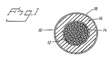
- FIG. 1 shows a cross-sectional view of a high voltage cable 10 which is used traditionally for the transmission of electric energy.
- the shown high voltage cable may for example be a standard XLPE cable 145 kV but without mantle and screen.
- the high voltage cable 10 comprises an electric conductor, which may comprise one or several strands 12 with circular cross-section of for example copper (Cu). These strands 12 are arranged in the centre of the high voltage cable 10.
- a first semi conducting layer 14 Around the strands 12 there is arranged a first semi conducting layer 14.
- a first insulating layer 16 for example XLPE insulation.
- Around the first insulating 16 there is arranged a second semi conducting layer 18.
- the high voltage cable 10, shown in Figure 1 is built with a conductor area of between 80 and 3000 mm 2 and an outer cable diameter of between 20 and 250 mm.
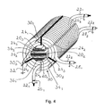
- Figure 2 shows a perspective view of windings with one earthing point per winding turn.
- Figure 2 shows a core leg designated by the numeral 20 within a power transformer or inductor.
- Two windings 22 1 and 22 2 are arranged around the core leg 20 which are formed from the high-voltage cable (10) shown in figure 1 .
- With the aim of fixing windings 22 1 and 22 2 there are, in this case, four radially arranged spacer members 24 1 , 24 2 , 24 3 , 24 4 per winding turn.
- the outer semi conducting layer is earthed at both ends 26 1 , 26 2 , 28 1 , 28 2 of each winding 22 1 , 22 2 .
- Spacer member 24 1 which is emphasised in black, is utilized to achieve one earthing point per winding turn.
- the spacer member 24 1 is directly connected to one earthing element 30 1 , i.e. in the form of an earthing track 30 1 , which is connected 32 to the common earth potential at the periphery of the winding 22 2 and along the axial length of the winding 22 2 .
- the earthing points rest (one point per winding turn) on a generatrix to a winding.
- Figure 3 shows a perspective view of windings with two earthing points per winding turn according to a first embodiment of the present invention.
- the same parts are designated by the same numerals in order to make the Figures more clear.
- the two windings 22 1 and 22 2 formed from the high-voltage cable 10 shown in Figure 1 , are arranged around the core leg 20.
- Spacer members 24 1 , 24 2 , 24 3 , 24 4 are also in this case radially arranged with the aim of fixing the windings 22 1 and 22 2 .
- the second semiconducting layer (compare with Figure 1 ) is earthed in accordance with Figure 2 .
- Spacer members 24 1 , 24 3 which are marked in black, are used in order to achieve two earthing points per winding turn.
- Spacer member 24 1 is directly connected to a first earthing element 30 1 and spacer member 24 3 is directly connected to a second earthing element 30 2 at the periphery of the winding 22 2 and along the axial length of the winding 22 2 .
- Earthing elements 30 1 and 30 2 may be in the form of earthing tracks 30 1 and 30 2 which are connected to the common earth potential 32.
- Both earthing elements 30 1 , 30 2 are coupled by means of an electric connection 34 1 (cable).
- the electric connection 34 1 is drawn into one slot 36 1 arranged in the core leg 20.
- the slot 36 1 is arranged such that the cross-section area A 1 of the core leg 20 (and thereby the magnetic flow ⁇ ) is divided into two partial areas A 1 , A 2 . Accordingly, the slot 36 1 divides the core leg 20 into two parts, 20 1 , 20 2 . This entails that currents are not magnetically induced in connection with earthing tracks. By earthing in the above-mentioned way the losses in the second semiconducting layer are kept to a minimum.
- Figure 4 shows a perspective view of windings with three earthing points per winding turn according to a second embodiment of the present invention.
- the same parts are designated by the same numerals in order to make the Figures more clear.
- two windings 22 1 and 22 2 formed from the high-voltage cable 10 shown in Figure 1 , are arranged around the core leg 20.
- Spacer members 24 1 , 24 2 , 24 3 , 24 4 , 24 5 , 24 6 are also radially arranged with the aim of fixing windings 22 1 and 22 2 . As shown in Figure 4 there are 6 spacer members per winding turn.
- the outer semiconducting layer (compare with Figure 1 ) is earthed as in accordance with Figures 2 and 3 .
- Spacer members 24 1 , 24 3 , 24 5 which are marked in black are used to achieve three earthing points per winding turn. These spacer members 24 1 , 24 3 , 24 5 are accordingly connected to the second semiconducting layer of the high power cable 10.
- Spacer member 24 1 is directly connected to a first earthing element 30 1 and spacer member 24 3 is directly connected to a second earthing element 30 2 and spacer member 24 5 is directly connected to a third earthing element 30 3 at the periphery of the winding 22 2 and along the axial length of the winding 22 2 .
- Earthing elements 30 1 , 30 2 , 30 3 may be in the form of earthing tracks 30 1 , 30 2 , 30 3 which are connected to the common earth potential 32. All three earthing elements 30 1 , 30 2 , 30 3 are joined by means of two electric connections 34 1 , 34 2 (cables).
- the electric connection 34 1 is drawn into a first slot 36 1 arranged in the core leg 20 and is connected to earthing elements 30 2 and 30 3 .
- the electric connection 34 2 is drawn into second slot 36 2 arranged in the core leg 20.
- Slots 36 1 , 36 2 are arranged such that the cross-section area A, of the core leg 20 (and thereby the magnetic flow ⁇ ) are divided into three partial areas A 1 , A 2 , A 3 . Accordingly slots 36 1 , 36 2 divide the core leg 20 into three parts 20 1 , 20 2 , 20 3 . This entails that currents are not magnetically induced in connection with earthing tracks. By earthing in the above-mentioned way losses in the second semiconducting layer are kept to a minimum.
- Figures 5a and 5b respectively, show a perspective view respectively a sectional view of a winding on an outer leg of a three phase transformer with three legs with three earthing points per winding turn according to a third embodiment of the present invention.
- a winding 22 1 formed from the high-voltage cable 10 shown in Figure 1 , is arranged around the outer leg 20 of the transformer. Additionally in this case spacer members 24 1 , 24 2 , 24 3 , 24 4 , 24 5 , 25 6 are arranged radially with the aim of fixing the winding 22 1 .
- the second semiconducting layer(compare with Figure 1 ) is earthed (not shown in Figures 5a and 5b respectively).
- Spacer members 24 1 , 24 3 , 24 5 which are marked in black, are used to achieve three earthing points per winding turn.
- Spacer member 24 1 is directly connected to a first earthing element 30 1
- spacer member 24 3 is directly connected to a second earthing element (not shown)
- spacer member 24 5 is directly connected to a third earthing element 30 3 at the periphery of the winding 22 1 and along the axial length of the winding 22 1 .
- Earthing elements 30 1 - 30 3 may be in the form of earthing tracks which are connected to the common earth potential (not shown).
- the three earthing elements 30 1 - 30 3 are joined by means of two electric connections 34 1 , 34 2 (cables).
- the two electric connections 34 1 , 34 2 are drawn in two slots 36 1 , 36 2 , arranged in a yoke 38 connecting the three earthing elements 30 1 - 30 3 to each other.
- the two slots 36 1 , 36 2 are arranged such that the cross-section area A of the yoke 38, (and thereby the magnetic flux ⁇ ) is divided into three partial areas A 1 , A 2 , A 3 .
- the electric connections 34 1 , 34 2 are threaded through the two slots 36 1 , 36 2 and over the front and back side of the yoke 38.
- Figure 6a and 6b respectively, show a perspective view respectively a sectional view of a winding, on a central leg of a three phase transformer with three or more legs, with three earthing points per winding turn according to a fourth embodiment of the present invention.
- a winding 22 1 formed from the high-voltage cable 10 shown in Figure 1 is arranged around the central leg 20 of the transformer. Additionally in this case spacer members 24 1 - 24 6 are arranged radially, three of which 24 1 , 24 3 , 24 5 are used to achieve three earthing points per winding turn.
- the spacer members 24 1 , 24 3 , 24 5 are directly connected to the earthing elements 30 1 - 30 3 , of which only two are shown, in the same way as described above in connection with Figures 5a, and 5b .
- the three earthing elements 30 1 - 30 3 are connected by means of two electric connections 34 1 , 34 2 (cables).
- the two electric connections 34 1 , 34 2 are drawn into two slots 36 1 , 36 2 arranged in a yoke 38.
- the two slots 36 1 , 36 2 are arranged such that the cross-section area A of the yoke 38 (and thereby the magnetic flux ⁇ ) is divided into three partial areas A 1 , A 2 , A 3 .
- the two electric connections 34 1 , 34 2 are threaded through slots 36 1 , 36 2 on both sides of the central leg 20 relative to the yoke 38.
- the principles used above may be used for several earthing points per winding turn.
- the magnetic flux, ⁇ is located in the core with a cross-section area A.
- the power transformer/inductor in the above shown figures comprises an iron core consisting of a core leg and a yoke. It should however be understood that a power transformer/ inductor may also be designed without an iron core (air-cored transformer).
Landscapes
- Engineering & Computer Science (AREA)
- Power Engineering (AREA)
- Coils Of Transformers For General Uses (AREA)
- Coils Or Transformers For Communication (AREA)
- General Induction Heating (AREA)
- Discharge Heating (AREA)
- Housings And Mounting Of Transformers (AREA)
Applications Claiming Priority (5)
| Application Number | Priority Date | Filing Date | Title |
|---|---|---|---|
| SE9700336 | 1997-02-03 | ||
| SE9700336A SE508765C2 (sv) | 1997-02-03 | 1997-02-03 | Krafttransformator/reaktor |
| SE9704412 | 1997-11-28 | ||
| SE9704412A SE9704412D0 (sv) | 1997-02-03 | 1997-11-28 | Krafttransformator/reaktor |
| PCT/SE1998/000153 WO1998034245A1 (en) | 1997-02-03 | 1998-02-02 | Power transformer/inductor |
Publications (2)
| Publication Number | Publication Date |
|---|---|
| EP1016102A1 EP1016102A1 (en) | 2000-07-05 |
| EP1016102B1 true EP1016102B1 (en) | 2009-07-08 |
Family
ID=26662862
Family Applications (1)
| Application Number | Title | Priority Date | Filing Date |
|---|---|---|---|
| EP98902350A Expired - Lifetime EP1016102B1 (en) | 1997-02-03 | 1998-02-02 | Power transformer/inductor |
Country Status (17)
| Country | Link |
|---|---|
| US (1) | US6970063B1 (zh) |
| EP (1) | EP1016102B1 (zh) |
| JP (1) | JP4372844B2 (zh) |
| KR (1) | KR20010049160A (zh) |
| CN (1) | CN1160746C (zh) |
| AT (1) | ATE436079T1 (zh) |
| AU (1) | AU724971B2 (zh) |
| BR (1) | BR9807141A (zh) |
| CA (1) | CA2276399A1 (zh) |
| DE (1) | DE69840964D1 (zh) |
| EA (1) | EA001725B1 (zh) |
| NO (1) | NO993671D0 (zh) |
| NZ (1) | NZ337096A (zh) |
| PL (1) | PL334615A1 (zh) |
| SE (1) | SE9704412D0 (zh) |
| TR (1) | TR199901585T2 (zh) |
| WO (1) | WO1998034245A1 (zh) |
Families Citing this family (12)
| Publication number | Priority date | Publication date | Assignee | Title |
|---|---|---|---|---|
| AU2795900A (en) * | 1998-12-23 | 2000-07-31 | Abb Ab | A high voltage transformer |
| WO2000039818A1 (en) * | 1998-12-23 | 2000-07-06 | Abb Ab | A high voltage inductor |
| AU2434900A (en) * | 1998-12-23 | 2000-07-31 | Abb Ab | A high voltage induction device |
| SE520942C2 (sv) | 2002-01-23 | 2003-09-16 | Abb Ab | Elektrisk maskin samt användning av sådan |
| US8350659B2 (en) * | 2009-10-16 | 2013-01-08 | Crane Electronics, Inc. | Transformer with concentric windings and method of manufacture of same |
| US20110090038A1 (en) * | 2009-10-16 | 2011-04-21 | Interpoint Corporation | Transformer having interleaved windings and method of manufacture of same |
| CN102082021B (zh) * | 2009-11-30 | 2012-02-22 | 成都深蓝高新技术发展有限公司 | 六孔铁心的三相电抗器 |
| US8901790B2 (en) | 2012-01-03 | 2014-12-02 | General Electric Company | Cooling of stator core flange |
| JP2017524232A (ja) | 2014-08-07 | 2017-08-24 | ヘンケル・アクチェンゲゼルシャフト・ウント・コムパニー・コマンディットゲゼルシャフト・アウフ・アクチェンHenkel AG & Co. KGaA | 束ねられた送電ケーブルにおける使用のためのワイヤの電気セラミックコーティング |
| WO2016061230A1 (en) * | 2014-10-17 | 2016-04-21 | 3M Innovative Properties Company | Dielectric material with enhanced breakdown strength |
| US9230726B1 (en) | 2015-02-20 | 2016-01-05 | Crane Electronics, Inc. | Transformer-based power converters with 3D printed microchannel heat sink |
| CN108429354B (zh) * | 2018-03-16 | 2021-08-17 | 河南师范大学 | 一种用于电动汽车的无线供电装置 |
Family Cites Families (104)
| Publication number | Priority date | Publication date | Assignee | Title |
|---|---|---|---|---|
| US1304451A (en) | 1919-05-20 | Locke h | ||
| US681800A (en) | 1901-06-18 | 1901-09-03 | Oskar Lasche | Stationary armature and inductor. |
| US847008A (en) | 1904-06-10 | 1907-03-12 | Isidor Kitsee | Converter. |
| US1418856A (en) | 1919-05-02 | 1922-06-06 | Allischalmers Mfg Company | Dynamo-electric machine |
| US1481585A (en) | 1919-09-16 | 1924-01-22 | Electrical Improvements Ltd | Electric reactive winding |
| US1756672A (en) | 1922-10-12 | 1930-04-29 | Allis Louis Co | Dynamo-electric machine |
| US1508456A (en) | 1924-01-04 | 1924-09-16 | Perfection Mfg Co | Ground clamp |
| US1728915A (en) | 1928-05-05 | 1929-09-24 | Earl P Blankenship | Line saver and restrainer for drilling cables |
| US1781308A (en) | 1928-05-30 | 1930-11-11 | Ericsson Telefon Ab L M | High-frequency differential transformer |
| US1762775A (en) | 1928-09-19 | 1930-06-10 | Bell Telephone Labor Inc | Inductance device |
| US1747507A (en) | 1929-05-10 | 1930-02-18 | Westinghouse Electric & Mfg Co | Reactor structure |
| US1742985A (en) | 1929-05-20 | 1930-01-07 | Gen Electric | Transformer |
| US1861182A (en) | 1930-01-31 | 1932-05-31 | Okonite Co | Electric conductor |
| US1904885A (en) | 1930-06-13 | 1933-04-18 | Western Electric Co | Capstan |
| US1974406A (en) | 1930-12-13 | 1934-09-25 | Herbert F Apple | Dynamo electric machine core slot lining |
| US2006170A (en) | 1933-05-11 | 1935-06-25 | Gen Electric | Winding for the stationary members of alternating current dynamo-electric machines |
| US2217430A (en) | 1938-02-26 | 1940-10-08 | Westinghouse Electric & Mfg Co | Water-cooled stator for dynamoelectric machines |
| US2206856A (en) | 1938-05-31 | 1940-07-02 | William E Shearer | Transformer |
| US2241832A (en) | 1940-05-07 | 1941-05-13 | Hugo W Wahlquist | Method and apparatus for reducing harmonics in power systems |
| US2256897A (en) | 1940-07-24 | 1941-09-23 | Cons Edison Co New York Inc | Insulating joint for electric cable sheaths and method of making same |
| US2295415A (en) | 1940-08-02 | 1942-09-08 | Westinghouse Electric & Mfg Co | Air-cooled, air-insulated transformer |
| US2251291A (en) | 1940-08-10 | 1941-08-05 | Western Electric Co | Strand handling apparatus |
| US2415652A (en) | 1942-06-03 | 1947-02-11 | Kerite Company | High-voltage cable |
| US2462651A (en) | 1944-06-12 | 1949-02-22 | Gen Electric | Electric induction apparatus |
| US2424443A (en) | 1944-12-06 | 1947-07-22 | Gen Electric | Dynamoelectric machine |
| US2459322A (en) | 1945-03-16 | 1949-01-18 | Allis Chalmers Mfg Co | Stationary induction apparatus |
| US2409893A (en) | 1945-04-30 | 1946-10-22 | Westinghouse Electric Corp | Semiconducting composition |
| US2436306A (en) | 1945-06-16 | 1948-02-17 | Westinghouse Electric Corp | Corona elimination in generator end windings |
| US2446999A (en) | 1945-11-07 | 1948-08-17 | Gen Electric | Magnetic core |
| US2498238A (en) | 1947-04-30 | 1950-02-21 | Westinghouse Electric Corp | Resistance compositions and products thereof |
| US2650350A (en) | 1948-11-04 | 1953-08-25 | Gen Electric | Angular modulating system |
| US2721905A (en) | 1949-03-04 | 1955-10-25 | Webster Electric Co Inc | Transducer |
| US2749456A (en) | 1952-06-23 | 1956-06-05 | Us Electrical Motors Inc | Waterproof stator construction for submersible dynamo-electric machine |
| US2780771A (en) | 1953-04-21 | 1957-02-05 | Vickers Inc | Magnetic amplifier |
| US2962679A (en) | 1955-07-25 | 1960-11-29 | Gen Electric | Coaxial core inductive structures |
| US2846599A (en) | 1956-01-23 | 1958-08-05 | Wetomore Hodges | Electric motor components and the like and method for making the same |
| US2947957A (en) | 1957-04-22 | 1960-08-02 | Zenith Radio Corp | Transformers |
| US2885581A (en) | 1957-04-29 | 1959-05-05 | Gen Electric | Arrangement for preventing displacement of stator end turns |
| CA635218A (en) | 1958-01-02 | 1962-01-23 | W. Smith John | Reinforced end turns in dynamoelectric machines |
| US2943242A (en) | 1958-02-05 | 1960-06-28 | Pure Oil Co | Anti-static grounding device |
| US2975309A (en) | 1958-07-18 | 1961-03-14 | Komplex Nagyberendezesek Expor | Oil-cooled stators for turboalternators |
| US3014139A (en) | 1959-10-27 | 1961-12-19 | Gen Electric | Direct-cooled cable winding for electro magnetic device |
| US3157806A (en) | 1959-11-05 | 1964-11-17 | Bbc Brown Boveri & Cie | Synchronous machine with salient poles |
| US3158770A (en) | 1960-12-14 | 1964-11-24 | Gen Electric | Armature bar vibration damping arrangement |
| US3098893A (en) | 1961-03-30 | 1963-07-23 | Gen Electric | Low electrical resistance composition and cable made therefrom |
| US3130335A (en) | 1961-04-17 | 1964-04-21 | Epoxylite Corp | Dynamo-electric machine |
| US3197723A (en) | 1961-04-26 | 1965-07-27 | Ite Circuit Breaker Ltd | Cascaded coaxial cable transformer |
| US3143269A (en) | 1961-11-29 | 1964-08-04 | Crompton & Knowles Corp | Tractor-type stock feed |
| US3268766A (en) | 1964-02-04 | 1966-08-23 | Du Pont | Apparatus for removal of electric charges from dielectric film surfaces |
| US3372283A (en) | 1965-02-15 | 1968-03-05 | Ampex | Attenuation control device |
| SE318939B (zh) | 1965-03-17 | 1969-12-22 | Asea Ab | |
| US3304599A (en) | 1965-03-30 | 1967-02-21 | Teletype Corp | Method of manufacturing an electromagnet having a u-shaped core |
| DE1488353A1 (de) | 1965-07-15 | 1969-06-26 | Siemens Ag | Permanentmagneterregte elektrische Maschine |
| US3365657A (en) | 1966-03-04 | 1968-01-23 | Nasa Usa | Power supply |
| GB1117433A (en) | 1966-06-07 | 1968-06-19 | English Electric Co Ltd | Improvements in alternating current generators |
| US3444407A (en) | 1966-07-20 | 1969-05-13 | Gen Electric | Rigid conductor bars in dynamoelectric machine slots |
| US3484690A (en) | 1966-08-23 | 1969-12-16 | Herman Wald | Three current winding single stator network meter for 3-wire 120/208 volt service |
| US3418530A (en) | 1966-09-07 | 1968-12-24 | Army Usa | Electronic crowbar |
| US3354331A (en) | 1966-09-26 | 1967-11-21 | Gen Electric | High voltage grading for dynamoelectric machine |
| US3392779A (en) | 1966-10-03 | 1968-07-16 | Certain Teed Prod Corp | Glass fiber cooling means |
| US3437858A (en) | 1966-11-17 | 1969-04-08 | Glastic Corp | Slot wedge for electric motors or generators |
| SU469196A1 (ru) | 1967-10-30 | 1975-04-30 | Двигатель-генератор установки дл электроснабжени пассажирских вагонов | |
| FR1555807A (zh) | 1967-12-11 | 1969-01-31 | ||
| GB1226451A (zh) | 1968-03-15 | 1971-03-31 | ||
| CH479975A (de) | 1968-08-19 | 1969-10-15 | Oerlikon Maschf | Wickelkopfbandage für eine elektrische Maschine |
| US3651402A (en) | 1969-01-27 | 1972-03-21 | Honeywell Inc | Supervisory apparatus |
| US3813764A (en) | 1969-06-09 | 1974-06-04 | Res Inst Iron Steel | Method of producing laminated pancake type superconductive magnets |
| US3651244A (en) | 1969-10-15 | 1972-03-21 | Gen Cable Corp | Power cable with corrugated or smooth longitudinally folded metallic shielding tape |
| SE326758B (zh) | 1969-10-29 | 1970-08-03 | Asea Ab | |
| US3666876A (en) | 1970-07-17 | 1972-05-30 | Exxon Research Engineering Co | Novel compositions with controlled electrical properties |
| US3631519A (en) | 1970-12-21 | 1971-12-28 | Gen Electric | Stress graded cable termination |
| US3675056A (en) | 1971-01-04 | 1972-07-04 | Gen Electric | Hermetically sealed dynamoelectric machine |
| US3644662A (en) | 1971-01-11 | 1972-02-22 | Gen Electric | Stress cascade-graded cable termination |
| US3660721A (en) | 1971-02-01 | 1972-05-02 | Gen Electric | Protective equipment for an alternating current power distribution system |
| US3684906A (en) | 1971-03-26 | 1972-08-15 | Gen Electric | Castable rotor having radially venting laminations |
| US3684821A (en) | 1971-03-30 | 1972-08-15 | Sumitomo Electric Industries | High voltage insulated electric cable having outer semiconductive layer |
| US3716719A (en) | 1971-06-07 | 1973-02-13 | Aerco Corp | Modulated output transformers |
| JPS4831403A (zh) | 1971-08-27 | 1973-04-25 | ||
| US3746954A (en) | 1971-09-17 | 1973-07-17 | Sqare D Co | Adjustable voltage thyristor-controlled hoist control for a dc motor |
| US3727085A (en) | 1971-09-30 | 1973-04-10 | Gen Dynamics Corp | Electric motor with facility for liquid cooling |
| US3740600A (en) | 1971-12-12 | 1973-06-19 | Gen Electric | Self-supporting coil brace |
| US3743867A (en) | 1971-12-20 | 1973-07-03 | Massachusetts Inst Technology | High voltage oil insulated and cooled armature windings |
| DE2164078A1 (de) | 1971-12-23 | 1973-06-28 | Siemens Ag | Antriebsanordnung mit einem nach art einer synchronmaschine ausgebildeten linearmotor |
| US3699238A (en) | 1972-02-29 | 1972-10-17 | Anaconda Wire & Cable Co | Flexible power cable |
| US3758699A (en) | 1972-03-15 | 1973-09-11 | G & W Electric Speciality Co | Apparatus and method for dynamically cooling a cable termination |
| US3716652A (en) | 1972-04-18 | 1973-02-13 | G & W Electric Speciality Co | System for dynamically cooling a high voltage cable termination |
| US3787607A (en) | 1972-05-31 | 1974-01-22 | Teleprompter Corp | Coaxial cable splice |
| JPS5213612B2 (zh) | 1972-06-07 | 1977-04-15 | ||
| CH547028A (de) | 1972-06-16 | 1974-03-15 | Bbc Brown Boveri & Cie | Glimmschutzfolie, verfahren zu ihrer herstellung sowie ihre verwendung bei hochspannungswicklungen. |
| US3801843A (en) | 1972-06-16 | 1974-04-02 | Gen Electric | Rotating electrical machine having rotor and stator cooled by means of heat pipes |
| US3792399A (en) | 1972-08-28 | 1974-02-12 | Nasa | Banded transformer cores |
| US3778891A (en) | 1972-10-30 | 1973-12-18 | Westinghouse Electric Corp | Method of securing dynamoelectric machine coils by slot wedge and filler locking means |
| US3932791A (en) | 1973-01-22 | 1976-01-13 | Oswald Joseph V | Multi-range, high-speed A.C. over-current protection means including a static switch |
| SE371348B (zh) | 1973-03-22 | 1974-11-11 | Asea Ab | |
| US3781739A (en) | 1973-03-28 | 1973-12-25 | Westinghouse Electric Corp | Interleaved winding for electrical inductive apparatus |
| US3881647A (en) | 1973-04-30 | 1975-05-06 | Lebus International Inc | Anti-slack line handling device |
| US3828115A (en) | 1973-07-27 | 1974-08-06 | Kerite Co | High voltage cable having high sic insulation layer between low sic insulation layers and terminal construction thereof |
| US3912957A (en) | 1973-12-27 | 1975-10-14 | Gen Electric | Dynamoelectric machine stator assembly with multi-barrel connection insulator |
| US4109098A (en) * | 1974-01-31 | 1978-08-22 | Telefonaktiebolaget L M Ericsson | High voltage cable |
| US3902000A (en) | 1974-11-12 | 1975-08-26 | Us Energy | Termination for superconducting power transmission systems |
| US4345804A (en) * | 1980-07-01 | 1982-08-24 | Westinghouse Electric Corp. | Flexible bushing connector |
| US5036165A (en) * | 1984-08-23 | 1991-07-30 | General Electric Co. | Semi-conducting layer for insulated electrical conductors |
| US4988949A (en) * | 1989-05-15 | 1991-01-29 | Westinghouse Electric Corp. | Apparatus for detecting excessive chafing of a cable arrangement against an electrically grounded structure |
| JP2000195345A (ja) * | 1998-12-28 | 2000-07-14 | Showa Electric Wire & Cable Co Ltd | 遮水ケ―ブル |
-
1997
- 1997-11-28 SE SE9704412A patent/SE9704412D0/xx unknown
-
1998
- 1998-02-02 JP JP53279598A patent/JP4372844B2/ja not_active Expired - Fee Related
- 1998-02-02 BR BR9807141-6A patent/BR9807141A/pt not_active IP Right Cessation
- 1998-02-02 WO PCT/SE1998/000153 patent/WO1998034245A1/en not_active Application Discontinuation
- 1998-02-02 CN CNB98801968XA patent/CN1160746C/zh not_active Expired - Fee Related
- 1998-02-02 EA EA199900701A patent/EA001725B1/ru not_active IP Right Cessation
- 1998-02-02 CA CA002276399A patent/CA2276399A1/en not_active Abandoned
- 1998-02-02 US US09/355,801 patent/US6970063B1/en not_active Expired - Fee Related
- 1998-02-02 AU AU58904/98A patent/AU724971B2/en not_active Ceased
- 1998-02-02 KR KR1019997006994A patent/KR20010049160A/ko not_active Application Discontinuation
- 1998-02-02 DE DE69840964T patent/DE69840964D1/de not_active Expired - Lifetime
- 1998-02-02 AT AT98902350T patent/ATE436079T1/de not_active IP Right Cessation
- 1998-02-02 NZ NZ337096A patent/NZ337096A/en unknown
- 1998-02-02 PL PL98334615A patent/PL334615A1/xx unknown
- 1998-02-02 EP EP98902350A patent/EP1016102B1/en not_active Expired - Lifetime
- 1998-02-02 TR TR1999/01585T patent/TR199901585T2/xx unknown
-
1999
- 1999-07-28 NO NO993671A patent/NO993671D0/no not_active Application Discontinuation
Also Published As
| Publication number | Publication date |
|---|---|
| US6970063B1 (en) | 2005-11-29 |
| JP2001509957A (ja) | 2001-07-24 |
| NZ337096A (en) | 2001-05-25 |
| EA001725B1 (ru) | 2001-08-27 |
| AU724971B2 (en) | 2000-10-05 |
| ATE436079T1 (de) | 2009-07-15 |
| JP4372844B2 (ja) | 2009-11-25 |
| NO993671L (no) | 1999-07-28 |
| CN1160746C (zh) | 2004-08-04 |
| AU5890498A (en) | 1998-08-25 |
| CA2276399A1 (en) | 1998-08-06 |
| DE69840964D1 (de) | 2009-08-20 |
| EP1016102A1 (en) | 2000-07-05 |
| TR199901585T2 (en) | 1999-09-21 |
| BR9807141A (pt) | 2000-01-25 |
| KR20010049160A (ko) | 2001-06-15 |
| PL334615A1 (en) | 2000-03-13 |
| WO1998034245A1 (en) | 1998-08-06 |
| EA199900701A1 (ru) | 2000-04-24 |
| SE9704412D0 (sv) | 1997-11-28 |
| NO993671D0 (no) | 1999-07-28 |
| CN1244290A (zh) | 2000-02-09 |
Similar Documents
| Publication | Publication Date | Title |
|---|---|---|
| EP1016103B1 (en) | Power transformer/inductor | |
| US6867674B1 (en) | Transformer | |
| EP1016102B1 (en) | Power transformer/inductor | |
| EP0901705B1 (en) | Insulated conductor for high-voltage windings | |
| EP0429843A1 (en) | Bushing for high direct voltages | |
| US11145455B2 (en) | Transformer and an associated method thereof | |
| EP1019922B1 (en) | Transformer/reactor | |
| WO1999028927A2 (en) | A power transformer/reactor | |
| WO1999017312A2 (en) | Power transformer/reactor and a method of adapting a high voltage cable | |
| EP1034607A1 (en) | Insulated conductor for high-voltage machine windings | |
| MXPA99006752A (en) | Power transformer/inductor | |
| EP0956569A1 (en) | A cable for electrical windings, and such a winding | |
| MXPA99006753A (en) | Power transformer/inductor |
Legal Events
| Date | Code | Title | Description |
|---|---|---|---|
| PUAI | Public reference made under article 153(3) epc to a published international application that has entered the european phase |
Free format text: ORIGINAL CODE: 0009012 |
|
| 17P | Request for examination filed |
Effective date: 19990903 |
|
| AK | Designated contracting states |
Kind code of ref document: A1 Designated state(s): AT BE CH DE DK ES FI FR GB GR IE IT LI LU NL PT SE |
|
| AX | Request for extension of the european patent |
Free format text: LT PAYMENT 19990903;LV PAYMENT 19990903;RO PAYMENT 19990903;SI PAYMENT 19990903 |
|
| GRAP | Despatch of communication of intention to grant a patent |
Free format text: ORIGINAL CODE: EPIDOSNIGR1 |
|
| GRAS | Grant fee paid |
Free format text: ORIGINAL CODE: EPIDOSNIGR3 |
|
| GRAA | (expected) grant |
Free format text: ORIGINAL CODE: 0009210 |
|
| AK | Designated contracting states |
Kind code of ref document: B1 Designated state(s): AT BE CH DE DK ES FI FR GB GR IE IT LI LU NL PT SE |
|
| AX | Request for extension of the european patent |
Extension state: LT LV RO SI |
|
| REG | Reference to a national code |
Ref country code: GB Ref legal event code: FG4D |
|
| REG | Reference to a national code |
Ref country code: CH Ref legal event code: EP |
|
| REG | Reference to a national code |
Ref country code: IE Ref legal event code: FG4D |
|
| REF | Corresponds to: |
Ref document number: 69840964 Country of ref document: DE Date of ref document: 20090820 Kind code of ref document: P |
|
| NLV1 | Nl: lapsed or annulled due to failure to fulfill the requirements of art. 29p and 29m of the patents act | ||
| LTIE | Lt: invalidation of european patent or patent extension |
Effective date: 20090708 |
|
| PG25 | Lapsed in a contracting state [announced via postgrant information from national office to epo] |
Ref country code: FI Free format text: LAPSE BECAUSE OF FAILURE TO SUBMIT A TRANSLATION OF THE DESCRIPTION OR TO PAY THE FEE WITHIN THE PRESCRIBED TIME-LIMIT Effective date: 20090708 Ref country code: ES Free format text: LAPSE BECAUSE OF FAILURE TO SUBMIT A TRANSLATION OF THE DESCRIPTION OR TO PAY THE FEE WITHIN THE PRESCRIBED TIME-LIMIT Effective date: 20091019 Ref country code: AT Free format text: LAPSE BECAUSE OF FAILURE TO SUBMIT A TRANSLATION OF THE DESCRIPTION OR TO PAY THE FEE WITHIN THE PRESCRIBED TIME-LIMIT Effective date: 20090708 |
|
| PG25 | Lapsed in a contracting state [announced via postgrant information from national office to epo] |
Ref country code: NL Free format text: LAPSE BECAUSE OF FAILURE TO SUBMIT A TRANSLATION OF THE DESCRIPTION OR TO PAY THE FEE WITHIN THE PRESCRIBED TIME-LIMIT Effective date: 20090708 |
|
| PG25 | Lapsed in a contracting state [announced via postgrant information from national office to epo] |
Ref country code: PT Free format text: LAPSE BECAUSE OF FAILURE TO SUBMIT A TRANSLATION OF THE DESCRIPTION OR TO PAY THE FEE WITHIN THE PRESCRIBED TIME-LIMIT Effective date: 20091109 |
|
| PG25 | Lapsed in a contracting state [announced via postgrant information from national office to epo] |
Ref country code: DK Free format text: LAPSE BECAUSE OF FAILURE TO SUBMIT A TRANSLATION OF THE DESCRIPTION OR TO PAY THE FEE WITHIN THE PRESCRIBED TIME-LIMIT Effective date: 20090708 |
|
| PLBE | No opposition filed within time limit |
Free format text: ORIGINAL CODE: 0009261 |
|
| STAA | Information on the status of an ep patent application or granted ep patent |
Free format text: STATUS: NO OPPOSITION FILED WITHIN TIME LIMIT |
|
| PG25 | Lapsed in a contracting state [announced via postgrant information from national office to epo] |
Ref country code: BE Free format text: LAPSE BECAUSE OF FAILURE TO SUBMIT A TRANSLATION OF THE DESCRIPTION OR TO PAY THE FEE WITHIN THE PRESCRIBED TIME-LIMIT Effective date: 20090708 |
|
| 26N | No opposition filed |
Effective date: 20100409 |
|
| REG | Reference to a national code |
Ref country code: CH Ref legal event code: PL |
|
| PG25 | Lapsed in a contracting state [announced via postgrant information from national office to epo] |
Ref country code: LI Free format text: LAPSE BECAUSE OF NON-PAYMENT OF DUE FEES Effective date: 20100228 Ref country code: GR Free format text: LAPSE BECAUSE OF FAILURE TO SUBMIT A TRANSLATION OF THE DESCRIPTION OR TO PAY THE FEE WITHIN THE PRESCRIBED TIME-LIMIT Effective date: 20091009 Ref country code: CH Free format text: LAPSE BECAUSE OF NON-PAYMENT OF DUE FEES Effective date: 20100228 |
|
| PG25 | Lapsed in a contracting state [announced via postgrant information from national office to epo] |
Ref country code: IE Free format text: LAPSE BECAUSE OF NON-PAYMENT OF DUE FEES Effective date: 20100202 |
|
| PG25 | Lapsed in a contracting state [announced via postgrant information from national office to epo] |
Ref country code: IT Free format text: LAPSE BECAUSE OF FAILURE TO SUBMIT A TRANSLATION OF THE DESCRIPTION OR TO PAY THE FEE WITHIN THE PRESCRIBED TIME-LIMIT Effective date: 20090708 |
|
| PGFP | Annual fee paid to national office [announced via postgrant information from national office to epo] |
Ref country code: DE Payment date: 20110126 Year of fee payment: 14 Ref country code: FR Payment date: 20110218 Year of fee payment: 14 |
|
| PGFP | Annual fee paid to national office [announced via postgrant information from national office to epo] |
Ref country code: GB Payment date: 20110209 Year of fee payment: 14 |
|
| PG25 | Lapsed in a contracting state [announced via postgrant information from national office to epo] |
Ref country code: SE Free format text: LAPSE BECAUSE OF FAILURE TO SUBMIT A TRANSLATION OF THE DESCRIPTION OR TO PAY THE FEE WITHIN THE PRESCRIBED TIME-LIMIT Effective date: 20090708 Ref country code: LU Free format text: LAPSE BECAUSE OF NON-PAYMENT OF DUE FEES Effective date: 20100202 |
|
| GBPC | Gb: european patent ceased through non-payment of renewal fee |
Effective date: 20120202 |
|
| REG | Reference to a national code |
Ref country code: FR Ref legal event code: ST Effective date: 20121031 |
|
| REG | Reference to a national code |
Ref country code: DE Ref legal event code: R119 Ref document number: 69840964 Country of ref document: DE Effective date: 20120901 |
|
| PG25 | Lapsed in a contracting state [announced via postgrant information from national office to epo] |
Ref country code: FR Free format text: LAPSE BECAUSE OF NON-PAYMENT OF DUE FEES Effective date: 20120229 Ref country code: GB Free format text: LAPSE BECAUSE OF NON-PAYMENT OF DUE FEES Effective date: 20120202 |
|
| PG25 | Lapsed in a contracting state [announced via postgrant information from national office to epo] |
Ref country code: DE Free format text: LAPSE BECAUSE OF NON-PAYMENT OF DUE FEES Effective date: 20120901 |