EP1015571B1 - Verfahren und vorrichtung für schnelle thermozyklen - Google Patents
Verfahren und vorrichtung für schnelle thermozyklen Download PDFInfo
- Publication number
- EP1015571B1 EP1015571B1 EP98951925A EP98951925A EP1015571B1 EP 1015571 B1 EP1015571 B1 EP 1015571B1 EP 98951925 A EP98951925 A EP 98951925A EP 98951925 A EP98951925 A EP 98951925A EP 1015571 B1 EP1015571 B1 EP 1015571B1
- Authority
- EP
- European Patent Office
- Prior art keywords
- cell
- steam
- reactor
- temperature
- membrane
- Prior art date
- Legal status (The legal status is an assumption and is not a legal conclusion. Google has not performed a legal analysis and makes no representation as to the accuracy of the status listed.)
- Expired - Lifetime
Links
Images


Classifications
-
- C—CHEMISTRY; METALLURGY
- C12—BIOCHEMISTRY; BEER; SPIRITS; WINE; VINEGAR; MICROBIOLOGY; ENZYMOLOGY; MUTATION OR GENETIC ENGINEERING
- C12N—MICROORGANISMS OR ENZYMES; COMPOSITIONS THEREOF; PROPAGATING, PRESERVING, OR MAINTAINING MICROORGANISMS; MUTATION OR GENETIC ENGINEERING; CULTURE MEDIA
- C12N15/00—Mutation or genetic engineering; DNA or RNA concerning genetic engineering, vectors, e.g. plasmids, or their isolation, preparation or purification; Use of hosts therefor
- C12N15/09—Recombinant DNA-technology
- C12N15/87—Introduction of foreign genetic material using processes not otherwise provided for, e.g. co-transformation
- C12N15/88—Introduction of foreign genetic material using processes not otherwise provided for, e.g. co-transformation using microencapsulation, e.g. using amphiphile liposome vesicle
-
- C—CHEMISTRY; METALLURGY
- C12—BIOCHEMISTRY; BEER; SPIRITS; WINE; VINEGAR; MICROBIOLOGY; ENZYMOLOGY; MUTATION OR GENETIC ENGINEERING
- C12N—MICROORGANISMS OR ENZYMES; COMPOSITIONS THEREOF; PROPAGATING, PRESERVING, OR MAINTAINING MICROORGANISMS; MUTATION OR GENETIC ENGINEERING; CULTURE MEDIA
- C12N13/00—Treatment of microorganisms or enzymes with electrical or wave energy, e.g. magnetism, sonic waves
Definitions
- the present invention relates to an in vitro method for all to cell fusion or cell to liposome fusion. More particularly, a rapid rise in temperature is employed in a manner which avoids denaturation of proteins while altering membrane properties.
- biological cells may be killed in a manner of Pasteurization, in which the time temperature product of a process is sufficient to denature cell proteins necessary for vitality.
- Other cell killing mechanisms are known which involve physical process, such as shear forces, ultrasonic cavitation, alteration in membrane properties through the insertion of pores, and the like.
- RTCP Rapid Thermal Cycle Processing
- Document WO 97/32483 is directed to a method for treating a cell, comprising the steps of heating the cell at a temperature rise rate of at least 1000°C per second, substantially without immediately killing the cell or thermally denaturing cell proteins.
- Document WO 90/15594 describes a method of delivering drug to a preselected target body site of a patient.
- the invention is a method according claim 1. Preferred embodiments are disclosed in the dependent claims.
- the present invention provides a rapid thermal cycle processing system which provides a high rate of temperature change, which primarily is directed to formed cell components, such as membranes.
- formed cell components such as membranes.
- the outer cell membrane is a focus of the action.
- the major aspects of the present invention do not rely on thermal denaturation of cellular proteins and enzymes, but rather on a rapid temperature rise which irreversibly changes the cell.
- a product is treated such that the temperature of a medium in which all or a portion of the cells exist rises at such a rapid rate that normal accommodation mechanisms, which might allow the cell to avoid permanent effect from a slower temperature rise rate treatment, are unavailable or ineffective.
- Cellular membranes are generally formed of phospholipid bilayers with proteins, lipoproteins and glycoproteins inserted on the inside, outside, or protruding through the membrane.
- the membrane especially the fatty acid chains of the phospholipids, are physiologically maintained in a fluid condition, and thus lipids and proteins are motile across the surface of the membrane.
- a lipid molecule may travel at a rate of about 2 microns per second, with proteins traveling at a rate of several microns per minute, in the plane of the membrane.
- Membrane components though mobile in the plane of the membrane, are generally slow to switch or invert between the outer and inner surface.
- transverse diffusion rate of phospholipids is about 10 -9 the rate of lateral diffusion, for a typical 50 ⁇ distance (the thickness of a phospholipid bilayer membrane).
- the viscosity of a cell membrane typically is about 100 times that of water.
- the membrane structures of living cells have some long-term ordering of molecules, especially the structures on the surface of the membrane (as opposed to the lipid phase in the middle of the membrane), and therefore are in this sense somewhat crystalline.
- the phrase "liquid crystal" is apt for the composite structure.
- the controlled membrane fluidity is believed to be necessary for various mediated transport systems which involve the movement of carriers within or through the membrane.
- the membrane proteins also have, in their natural state, a separation of charged and uncharged portions, allowing stable insertion of lipophilic portions of the proteins into the membrane structure, with hydrophilic portions protruding extracellularly or intracellularly from the membrane, into the cytoplasm or extracellular fluid. Intracellular membranes may also have asymmetry.
- the long term ordering of the membrane along its surface is related to arrangements of the protein components and the polar end-groups of the phospholipids.
- Some of the proteins or protein structures which extend through the membrane provide channels which allow ions, such as sodium, potassium and chloride to readily cross, or to be selectively controlled or pumped. The size of the channel allows selectivity between differing ions, e.g., sodium and potassium.
- the tertiary configuration of the proteins (the three dimensional structure of a single protein molecule), and quaternary configuration of peptide structures (the spatial interaction of separate molecules) are thus critical for proper protein insertion in the membrane, and protein functioning.
- the membrane is ordered, and this ordering relates to its function. A disruption of the ordering affects the cell function, and may destroy the cell, or have a lesser damaging, distinct or selective effect.
- the membrane fluidity may be controlled by fatty acid composition.
- bacteria use this mechanism.
- the fatty acyl chains of lipid molecules may exist in an ordered, crystal-like state or in a relatively disordered fluid state. The transition from the ordered to disordered state occurs when the temperature is raised above a "melting" temperature, or more properly, a glass transition temperature.
- the physiological state is fluidic.
- the membrane structure may have a number of different glass transition temperatures, for the various components and their respective energetically favorable orderings which may exist. This glass transition temperature depends on a number of factors, including the length of the fatty acyl side chain and their degree of unsaturation.
- Unsaturation (with the naturally occurring cis-oriented carbon-carbon bonds) causes "kinks" in the side chains, and increases bond rotation on either side of the unsaturation, both of which impair orderly packing, thus reducing crystallinity and increasing the glass transition temperature.
- Long fatty acyl chains interact more strongly, stabilizing the structure, and in increase in their proportion leads to a decrease in glass transition temperature.
- Higher organisms have cholesterol in their membranes, which increases membrane fluidity.
- the cholesterol content may be controlled to control fluidity.
- High temperature change rates are needed in order to prevent the relaxation of structural changes in a cell, e.g., the cellular membrane, which occur over approximately 10-100 mS. With temperature rise rates in excess of this rate, an effect occurs, which may, for example, disrupt or inactivate bacteria or cells or have other effects.
- the induced thermal shock thus produces a number of effects on the cell.
- the cell rapidly expands due to the increase in temperature.
- the cellular membranes may experience a configurational change either as a primary effect or secondarily due to a phase, volume or shape change of cellular components.
- thermal shock may effectively reduce quaternary organization to control or alter the cell. Microtubule structures and nucleic acid conformations may also be affected.
- one method for inducing this controlled yet rapid temperature rise is by treating medium containing the cells, generally in relatively small droplets to provide a large surface area to volume ratio and small thermal inertia, held at a starting temperature, with an excess of steam at the desired final temperature.
- the interaction between the droplets and steam is rapid, equilibrating within milliseconds at the final temperature, with only a small amount of dilution due to the high latent heat of vaporization of steam.
- the droplets are degassed prior to treatment.
- a microwave device may be used, which heats the medium through molecular excitation.
- the power of the microwave is controlled so that the medium is heated to a desired temperature over a desired period.
- the energy is applied rapidly, in order to obtain the desired temperature rise rate, e.g., in excess of 1000°C per second, over a short period.
- Blood presents certain interesting properties material to its application for treatment according to the present invention.
- blood treatment may be effected through the steam chamber, using treatment parameters which do not coagulate or denature blood proteins.
- a useful blood treatment does not attempt to kill all blood cells, or one would simply extravasate without reinfusion, or separate undesired cell components and not reinfuse undesired components.
- a goal of therapy is either selective treatment of a subpopulation of the cells, or a non-lethal treatment applied non-selectively to all or some of the cells present.
- a non-lethal treatment In order to effect a non-lethal treatment, the temperature rise rate is controlled, and/or the temperature rise and/or maximum temperature is controlled.
- Blood treatments may be effective, for example, to treat chronic fatigue syndrome (CFS), acquired immune deficiency syndrome (AIDS), malaria, babesiosis, other viral, bacterial, fungal or parasitic diseases, leukemias or other blood-borne neoplasms, blood dysplasias and dyscrasias, immune disorders and syndromes.
- CFS chronic fatigue syndrome
- AIDS acquired immune deficiency syndrome
- Bacterial-associated autoimmune mediated disorders such as those related to spirochetes (syphilis, Lyme disease), as well as other autoimmune related diseases, such as rheumatoid arthritis and lupus, may also be subject to treatment according to the present invention. This later treatment may be applied, for example, to lymphocytes, which mediate immune responses.
- a stream of blood, or blood component(s) may be subjected to a controlled low power CO 2 laser or microwave treatment to effect the temperature shock treatment.
- cell separation techniques such as those developed by Coulter Electronics, Hialeah, FL, individual blood cells may be separated and individually treated, based on an identification of type, and then, for example, reinfused into the host.
- the cell treatment methods according to the present invention may also be applied to in vitro techniques in order to control cells or select cell subpopulations.
- Typical applications include, for example, genetic engineering clonal selection for temperature shock resistance genes, which may be either a primary goal or a marker gene for a linked trait.
- the technologies include the use of an apparatus which atomizes a fluid to a uniform small droplet size and subjects the droplets to a treatment
- the process treatment passes the droplets through a steam chamber at controlled temperature, which results in a rapid heating and thermal equilibrium of the droplets.
- the droplets are expelled from an atomizer nozzle at high velocity, so that the residence time in the steam chamber is limited. Since the maximum temperature is tightly controlled, this allows precise treatment parameters based on droplet size, velocity, steam temperature and pressure, and the presence of gasses other than water vapor.
- the treatment also is influenced by the deceleration of the droplets after treatment, a small dilution factor due to condensed steam, and the cooling of the fluid droplets after treatment.
- the equilibration to the steam temperature is so rapid, in fact, due to the high latent heat of vaporization of steam, that a thermal shock is generated in the droplets.
- This rapid rise in temperature is accompanied by a mechanical expansion, which generates a mechanical shock wave in the droplet.
- the steam condensation also produces an osmotic "shock", with up to 10-15% dilution, synchronized with the thermal-induced shock.
- the droplets are atomized, pass through the steam chamber at a velocity of about 20 meters per second, and are decelerated, for example by impact, resulting in a further synchronized mechanical shocks.
- the parameters of a bulk medium steam treatment process which control the efficiency include starting and ending temperatures, steam overheating, rate of temperature rise, degassing procedure (if any), pressure, pre- or post-treatments, pH, droplet size and distribution, droplet velocity, and equipment configuration.
- systems operable for milk Pasteurization have been tested using various parameters. For example a test has been conducted with a temperature rise from about 46°C to about 70.8°C, with a milk pH of 6.60 (start) to 6.65 (finish), and a dilution of 2.5%. Droplet size is preferably about 0.2-0.3 mm.
- the rate of temperature rise is, for example, in excess of 1500°C per second, and more preferably above 2000°C per second.
- the bulk medium steam treatment apparatus provides a rapid temperature rise by subjecting relatively small droplets of less than about 0.3 mm to dry steam (non-supercritical) at a partial pressure less than about 760 mm Hg.
- a low partial pressure of non-condensing gasses e.g., less than about 100 mm Hg, and more preferably below about 50 mm Hg
- the partial pressure of steam is about 0.3-0.8 atmospheres (e.g., about 225-620 mm Hg).
- the steam is saturated, and thus the temperature of the steam is held at a desired final temperature, e.g., 40-75°C.
- the steam temperature-pressure relationships are well known, and need not be reviewed herein.
- Droplets of medium including cells to be treated are atomized under force through a nozzle, into a reduced pressure reactor chamber containing the steam. Under this partial vacuum, residual gasses are drawn out of the droplet, which may form a boundary layer, reducing heat transfer rate; therefore, it is preferred that the bulk medium to be treated is degassed prior to treatment.
- the droplets contact steam, which condenses on the relatively cooler droplets and heats the droplets through release of the latent heat of vaporization. As the steam condenses, the droplets are heated, until they reach the equilibrium temperature of the steam, at which time there is no further net condensation of steam. The droplets will not get hotter than the steam in the chamber, so that the steam temperature sets the maximum temperature.
- the droplets may not reach equilibrium, and thus may reach a maximum temperature somewhat cooler then the steam.
- the initial interaction of the droplet with the steam will produce the highest temperature change rate, so that the reactor system may be designed to operate at a steady state which does not achieve equilibrium temperature.
- parameters should be tightly controlled to assure complete treatment without overtreatment, and thus a maximum temperature above a desired level.
- a vacuum pump may be provided which continuously withdraws gas, with a port near the droplet injection nozzle, removing the non-condensing gasses and some steam.
- the product to be treated is fully degassed prior to entry into the reactor, and thus there will be little or no buildup of non-condensing gasses which require evacuation from the reaction vessel during processing.
- the droplet rapidly equilibrates with the steam temperature under the pressure conditions, over a distance of less than one meter, for example within 70 mm from the droplet injection nozzle.
- the so-treated droplets are then collected, and may be immediately cooled, thus limiting any adverse effects of long-term exposure to the steam temperature.
- the steam is provided by a steam generator, which boils, for example, potable or distilled water. This water is degassed prior to use, so that the steam contains few impurities and almost no non-condensing impurities.
- the steam generator may be at any temperature above the final temperature, e.g., 150°C, as the thermal treatment of the droplets derives mainly from the latent heat of vaporization of the droplets, and very little from the absolute temperature of the steam.
- the steam is saturated, which will define its temperature in a given atmosphere. If the steam is sub-saturation, condensation of steam on the droplets will be impeded. If the steam is supersaturated, it will itself form droplets and impede the process, in addition to diluting the medium. Process temperature control will also be adversely affected, and may be less predictable.
- the mass flow rate of the saturated steam entering into the treatment system controls the process treatment temperature.
- the mass flow rate is restricted to prevent the treated droplets from reaching too high a temperature, or supersaturation conditions.
- the steam is injected adjacent to the path of the droplets being treated, to ensure equilibration by the time the droplet reaches the terminus of the reactor. Due to boundary layer effects of the droplet, due to, for example, non-condensing gasses, as well as diffusion limitations, the temperature rise is not instantaneous.
- steam has a latent heat of vaporization of 540 cal/ml; therefore, a 5% ratio of steam to aqueous fluid to be processed will result in an approximately 27°C rise in temperature.
- the resultant 5% dilution may be inconsequential, or remedied in a later step.
- the medium is sprayed through a nozzle as a stream of small droplets into a reaction vessel.
- the size of these droplets is preferably less than 0.3 mm, though if the droplets are too small they may present other difficulties, such as poor
- the droplets may be electrostatically charged, and then normally diverted from a direct path. Droplets of too large a mass will be diverted less, and may be separately collected. Alternately, an entire stream segment may be diverted if a flaw (untreated or untreatable portion) in the treatment is detected. For example, an optical detector may detect a large droplet traversing the reactor and divert the outlet for a period of time to flush any contaminants.
- An electrostatic or magnetic diversion system may also be employed to electrostatically charge droplets and then separate large droplets from small droplets.
- the fluid to be treated contains other volatile compounds, such as ethanol
- such vapors may evaporate from the droplets, especially at elevated temperatures. This produces two effects. First, a boundary layer is created by the net outward mass flow, which may impede steam contact and heating. Second, depending on the temperature and pressure, the heating of the droplet may be counteracted by the loss of heat of vaporization of the volatile component. Therefore, care must be taken to ensure that the fluid droplets do not reach the end of the reactor and pool prior to being raised to the desired temperature, or that the temperature rise rate is insufficient. It may also be necessary to inject alcohol vapor with the steam to maintain equilibrium conditions in the reactor. It is noted that the reactor may also be used to reduce or vary alcohol concentrations of the fluid being treated, by varying the treatment conditions. For example, alcohol vapors may be withdrawn and captured through a vacuum pump, along with non-condensing gasses and some steam. This allows the production of a "light" alcoholic beverage, while killing yeast or other organisms.
- the RTCP technique under appropriate conditions, has the ability to alter cells, without significant denaturation of most proteins. There are three mechanisms postulated to exert effects on the cells:
- the RTCP system is tuned to provide a controlled thermal effect, limited osmotic stress (associated with the temperature rise), and minimized mechanical stress.
- limited osmotic stress associated with the temperature rise
- mechanical stress associated with the temperature rise
- One of the membranes may be of a eukaryotic organism, for example a mammal.
- the cell is preferably an erythrocyte or lymphocyte composition.
- the system may be used for example to fuse cells with two or more types of liposomes.
- the membrane may also be a a liposome.
- the liposome may have a specific composition on its surface (outer or inner) or interior.
- the composition may be a pharmaceutical, nutrient, oxidant or antioxidant, cytokine, enzyme (e.g., glucose-6-dehydrogenase), protein, receptor, receptor binding ligand, receptor agonist or antagonist, hormone, gene regulatory agent, antibody or portion thereof, cytotoxic agent, redox state altering composition, pH altering composition, viral protein, viral receptor protein, nucleic acid (e.g., nucleic acid encoding at least one gene or regulator).
- cytokine enzyme
- protein e.g., glucose-6-dehydrogenase
- receptor receptor binding ligand
- receptor agonist or antagonist hormone, gene regulatory agent, antibody or portion thereof
- cytotoxic agent redox state altering composition
- pH altering composition viral protein, viral receptor protein, nucleic acid (e.g., nucleic acid encoding at least one gene or regulator
- the product may be stored, for example for hours, days or longer, or further processed or employed in a medical treatment.
- the product may also be used in industrial or biotechnical processes.
- the cells an/or medium may be injected or infused into an animal, for example intravenous or directed to lymphatic pathways.
- the membranes or medium may be subject to other conditions, such as oxidizing or reducing agents, antioxidant (free radical trapping) agents, photonic or microwave radiation treatment, turbulence or shear forces, or the like.
- a non-thermal bactericidal treatment may therefore be applied in conjunction with the heat treatment.
- the medium may be filtered to remove most bacteria.
- the membrane may be fused.
- a cell may be killed or remain alive as a result of the treatment.
- two different membrane structures are subjected to treatment, one membrane structure having an effective glass transition temperature below an average glass transition temperature of the other.
- One of the structures may be homogeneous while the other is heterogeneous, e.g., a mosaic domain structure as hypothesized by Singer and Nichols.
- the heat treatment my therefore induce a gel to liquid state transition in at least a portion of one membrane.
- the temperature rise rate may exceed an accommodation rate of the membrane.
- the rapid heating may, for example, cause at least a portion of a lipid bilayer membrane to enter a non-bilayer state.
- the heating may also cause a non-linear change in packing density of molecules forming a membrane.
- a cell may be incubated under such conditions as to alter a cell membrane lipid composition.
- the temperature rise rate is, e.g., greater than 100 C per second, and may be greater than 1000 C per second.
- the temperature rise may be greater than 10 C, for example 25 to 40 C, and the maximum process temperature may be less than 55 C, preferably less than 49 C, and possibly as low or lower than 43 C.
- the heat treatment preferably does not substantially denature cellular proteins, although under certain conditions, denaturation of at least certain proteins may be desired.
- the heating may be effected, for example, by water vapor or steam, which is preferably "superheated” or “dry” to reduce spontaneous condensation.
- An inert, non-condensing gas may be present during treatment, or the treatment may be conducted with low non-condensing gas levels. Thus, non-condensing gasses may be added or removed during treatment.
- the medium is preferably degassed prior to treatment.
- the medium is preferably atomized prior to heating.
- the atomized medium is preferably heated while moving at a velocity of at least about 10 cm/sec, preferably at least 100 cm/sec, and more preferably 1000 to 2000 cm/sec or higher.
- the medium may be subject to mechanical forces synchronized with and independent of the heating.
- the apparatus which is not part of the invention has, for example, a processing capacity of between about 0.25 - 125 ml per minute, and preferably a processing capacity of between about 1-25 ml per minute.
- the apparatus may have a transparent treatment chamber, for example made of glass, e.g., borosilicate glass or of fused quartz.
- the apparatus may also include an automated or assisted cleaning cycle to achieve sterilization and/or to remove deposits.
- the apparatus preferably has a control, the control being programmed to detect a treatment aberration.
- two cells are fused in order to achieve a hybrid.
- a process includes treatment of a malignant or immortalized cell and differentiated cell to result in a cell having differentiated characteristics, such as specific gene products, e.g., a significant secreted gene product, such as an antibody.
- the resulting cell line may therefore produce, e.g., a monoclonal antibody from an immunoglobulin secreting hybridoma.
- the apparatus includes a steam generator and superheater, a pressurizer for the control and test solutions, a degasser, a steam treatment chamber, and a sample collection system.
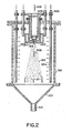
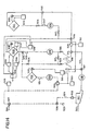
- Fig. 1 shows a simplified diagram of a steam condensation reactor vessel according to the present invention.
- the reactor is formed of an upper body 203 and a lower body 204, with a seal 205 therebetween.
- a fluid to be treated which may be a growth medium, milk, or blood component, is degassed according to conventional procedures, preferably to a level of at most 50 mm Hg non-condensable gasses, and more preferably to a level of no more than 20 mm Hg non-condensable gasses.
- the degassed fluid enters the reactor at approximately 22°C through a conduit 201 having an atomizer, which produces a spray of small fluid droplets, dispersed in the reactor space 210.
- the pressure in the reactor is held at approximately 0.5 atmospheres by a vacuum control system 207, which is provided with a baffle 206 to prevent withdrawal of fluid to be processed.
- the baffle 206 also serves to insulate the reactor space from the upper body 203.
- the reactor space is filled with steam, e.g., substantially pure water vapor from steam injectors 202.
- the steam is provided at equilibrium, and thus the vapor pressure of the steam at the temperature of the reactor, i.e., approximately 55°C, is equal to the pressure of the reactor.
- the steam will tend to condense on the fluid droplets, releasing their latent heat of vaporization, heating the droplets, until the droplets reach the temperature of the steam.
- a partial vacuum is created around the droplet, causing a net mass flow into the droplet.
- up to 10% by weight of steam may be absorbed; but generally the amount will be limited to 2-5%.
- the droplets are ejected from the atomizer at approximately 20 meters per second.
- the total height of the reactor space is approximately 30 centimeters.
- the residence time of droplets within the reactor, before hitting the lower body 204 is at most about 15 mS. Therefore, the temperature of the droplets rises from 20°C to 55°C in about 15 mS, thus yielding a temperature rise rate of at least about 2300°C per second. In fact, the maximum rise rate will likely be higher, because the steam equilibrates with the droplets before reaching the end of the reactor.
- Fig. 2 shows a reactor in more detail.
- the reactor is similar in operation to the reactor detailed in Fig. 1 .
- the reactor is formed of a cover 302, and a shell 301.
- a lower conical base 313 is provided below the shell 301.
- the fluid to be processed is injected through plenum 306, with an atomizer structure 312, which produces, e.g., 5 micron fluid droplets in a fast moving stream 309.
- Steam is injected through a dual manifold system 305, which includes series of central, upper injection ports 308, which provide a relatively high flow of steam near the atomizer structure 312, and a series of risers 304 which allow for reduced macroscopic pressure gradients within the reactor.
- a cooling jacket 307 is provided having circulating cooling water around the plenum 306.
- the fast moving stream 309 reacts with the steam injected through the upper injection ports 308 and the risers 304, and becomes a heated fluid 310 at approximately the steam temperature.
- the heated droplets continue through the reactor, and reach equilibrium with the steam, as equilibrated droplets 311, and condense against the conical base 313 and exit the reactor through exit port 314.
- a vacuum is drawn on the exit port to exhaust any accumulation of non-condensable gasses from the reactor during operation, to maintain the reactor in a steady state condition.
- Table 1 shows various operating parameters of a preferred reactor design according to the present invention. TABLE 1 Parameter Milk Vapor Flow Kg/hr 1000 100 Pressure in entrance of Processor 0.4 0.1 Steam temperature in Processor, °C 40-100 Processor volume 0.1 48.8
- Fig. 3 shows a bactericidal system incorporating the reactor 401.
- the fluid to be treated e.g., milk
- the fluid to be treated is provided in a degassification chamber 402, provided with a control valve 411 to a vacuum pump 409.
- the fluid is transported with a pump 407, through a valve 406, to the injection plenum of the reactor 401.
- the reactor 401 is also connected to the vacuum pump 409 through a separate valve 405 for startup cleansing of the reactor 401 and scavenging of non-condensable gasses. Pooled fluid accumulates at the bottom of the reactor 401, and is drawn to a processed fluid holding tank 404, where it may be drained through valve 410.
- the fluid holding tank is also connected to the vacuum pump through valve 408, to allow a gradient for withdrawing processed fluid from the base of the reactor 401.
- a steam generator 403 provides steam through control valve 412 to the reactor 401, controlling the temperature in the reactor 401, e.g., between about 40°C and 90°C, depending on the desired conditions.
- Fig. 4 shows a bactericidal system similar to the system described in Example 1, with the identification of elements for testing and controlling various conditions within the reactor system.
- the steam generator 403 is provided with a sight glass 428 for determining water volume, thermocouples T8 and T9 for determining temperature, pressure gage 437 and an electrical heater 428. Water enters the steam generator 403 from reservoir 427 through valve 426.
- the degassification chamber 402 shows a system which partially replaces air, with argon 424, through control valve 411.
- the motive force for driving the medium from the chamber 402 through the nozzle is the argon 424 pressure.
- argon 424 is a non-condensable gas, the amount which dissolves is relatively low during a treatment period.
- a thermocouple T10 and pressure gage 423 are also provided.
- a heater 430 is provided to heat the outer shell of the reactor 401.
- the steam is injected through a pair of control valves 412a, for an annular manifold and 412b, for a riser manifold, into the reactor.
- a pair of thermocouples T6 and T7 are provided to measure the steam temperature.
- thermocouples T0, T1, T2, T3, T4 and T5 allow determination of temperature gradients within the reactor at steady state conditions.
- the vacuum pump acts through valve 422 and line 421 through water trap 420 and valve 405.
- the vacuum also acts through valve 434 to draw pooled fluid from the reactor 401, through valve 431.
- Valves 432, 433 and 435 allow use of sample 436, without disrupting reactor operation.
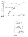
- Figs. 12 and 13 show results of testing the bactericidal effect of the reactor system according to the present invention.
- Figs. 12 and 13 show results of testing the bactericidal effect of the reactor system according to the present invention.
- Figs. 12 and 13 thus show that bacterial kill to survive ratios increase with increasing steam pressure ( Fig. 12 ) and that degassification of the chamber improves bacterial killing as well ( Fig. 13).
- Fig. 13 also demonstrates the effects of the relationship of fluid flow rate to steam flow rate.
- Fig. 5 shows a modified bactericidal system, as compared with Example 1, in which at least a portion of the degassification is performed in-line, rather than in primarily in batch mode. Further, the reactor forms a part of the degassification system.
- a holding chamber 6 is provided for milk 5.
- a partially decompressed gas space 4 is provided, acted upon by a low vacuum pump 8 through vacuum line 7, to vent 9. This acts as a first stage of the degassification process.
- Fresh milk is fed to the holding chamber through an inlet conduit 2 having a valve 63 and inlet port 3.
- the partially degassed milk 11 is fed through fluid feed line 10 to a feed pump 53, through line 13, to a vortex degassification system 50, having vacuum pump 62 through vacuum line 61.
- the milk 51 swirls under vacuum conditions to exit port 52, and is pumped into the processor with pump 12.
- the milk is then atomized within the reactor vessel, of the processor shell 28 and the conical pooling region 32, behind a baffle 55.
- the region proximate to the atomizer 54 is drawn under vacuum by vacuum pump 60 through line 59, to about 20 mm Hg pressure.
- the atomized droplets 56 have a high surface area to volume ratio, and degas readily under these conditions.
- the degassed droplets pass through an aperture 57 of the baffle 55, and enter the main portion of the reactor vessel, coming into contact with steam at approximately 55°C. In this region, equilibrium is not achieved, and a net mass flow of steam will tend to be drawn upward through the aperture.
- the droplets are cool, i.e., the milk stream is provided at approximately 22°C, and the droplets are further cooled by the degassification treatments, the steam will tend to immediately condense on the droplets, causing a rapid heating.
- the steam 29 is injected into the reactor through a vertical steam distribution riser system 27, fed by steam distribution manifold 26, through steam injection line 24, pressure regulator 22, with relief port 23, from steam generator 18 having steam space 119.
- the steam generator is heated electrically by electrical heater 20, controlled by control 40 with temperature sensor 41 and power source 42. Water is fed to the steam generator 18 through water feed line 17.
- Processed milk 58 contacts the conical neck 33 of the reactor and pools 34 at the lower portion, and is withdrawn through outlet line 35, through pump 36, to processed milk outlet 37.
- a pilot plant reactor system is shown in Figs. 14-15 .
- This system allows optimization of process parameters, and is capable of continuous operation, however, as a pilot plant, is generally is operated with a 15 liter fluid reservoir.
- the system operates on the principle of heating droplets using condensing steam in a vacuum chamber, which is held a constant subatmospheric pressure by a vacuum pump.
- the pressure within the steam generator is measured with a compound pressure and vacuum gauge 612.
- the atomization of the fluid is implemented through a nozzle, into which the product is fed under the pressure, for example generated by and inert gas (argon) source, at a pressure in excess of 4-5 atmospheres, through gas/vacuum valve 613.
- the level of water within the steam generator may be determine by viewing the glass level gauge 611.
- the major components of the system exclusive of controls, include a steam generator 601, a Pasteurization reactor 602, a raw product tank 603, a Pasteurized product tank 604, a vacuum collector 616, a drain tank 606, a condensate tank 607, and an inert gas feed-in system to the raw product tank 609.
- the vacuum system includes water circuit pump 626 and vacuum oil pump 620, which can operate individually or following the scheme: the gasses from the vacuum collector 616 are pumped out to a vacuum pump 620, and/or to a water circuit pump 626.
- a steam condenser 621 which has its own water feed-in 622 and feed-out system, is installed between the reactor 602 which undergoes evacuation and the pumping system.
- the vacuum collector 616 drains to a condensate tank 615.
- thermocouple ⁇ 1°C resolution
- diaphragm pressure gauges 10 Pa resolution
- Thermocouples are installed in the water and steam units of the steam generator 601, in the reactor 602 near the nozzle, located near the top of the reactor 602 (seven in all) for the purpose of gauging temperatures in a steam-droplet mixture at the product drain line 631 in the reactor 602, and in the tanks of raw 603 and Pasteurized 604 products.
- Pressure is measured in a steam collector 632 and in the bottom part of the reactor 634.
- the sample to the mass spectrometer 623 is passed through a mass spectrometer sampler tank 618, the pressure of which may be determined by pressure gauge 617.
- a vacuum pump 619 draws the sample gas into the mass spectrometer sampler tank 618.
- the mass spectrometer is connected to a magnetodischarge diode cooled pump 627.
- Vacuum processing of the reactor 602 during operation is implemented in two locations: in the upper part 635 of the reactor 602, near the nozzle 637 for the purpose of degassing raw product from tank 603; and in the bottom part 636 through the reactor 602, around a system of shields, which is the main passage to the vacuum processing system.
- Samples of the processed product are taken directly from the stream of the processed product, into disposable syringes, through the drain line 606 of the reactor 602.
- the Pasteurizer reactor system consists of a number of components.
- a nozzle 637 (sprayer) for atomizing milk or any other liquid product to be Pasteurized, into drops.
- the nozzle 637 is of a standard, centrifugal, dismantling type.
- the outlet ring 646 of the nozzle 637 is replaceable, its diameter being equal to 4.8 mm for the water consumption of 1 liter per second at a pressure 0.4-0.5 MPa and 2 mm for the water consumption of 0.15 liters per second.
- the vortex segment 647 of the nozzle 637 has the following dimensions: diameter equal to 27 mm, with the height of the cylindrical part equal to 6.5 mm.
- the vortex forming ring 645 has 6 triangular grooves 3.2 x 3.2 mm at an angle of 45° to the horizontal plane.
- the nozzle 637 When the inlet 648 is closed, the nozzle 637 is operating as centrifugal. When the inlet 648 is open, operates in a jet-centrifugal mode.
- the jet-centrifugal mode of the nozzle 637 fills the cone practically to capacity at a dispersion angle of 90°.
- the purely centrifugal mode of the nozzle 637 has the center of the cone empty, but the drops are of more homogeneous dimensions.
- the nozzle has a non-toxic rubber seal 643.
- the body of the reactor is attached to the shield 704 and the steam collector 705, with inlets of 5 mm in diameter for steam dispensing the reactor.
- the placement of the inlets and their number are optimized by way of empirical testing depending upon the product consumption and the dimensions of its drops.
- the upper part of the steam collector 705 includes two welded pipes 720 for dry (or slightly superheated for 10°C-20°C) food steam.
- the non-condensing gas is evacuated through the space between the shield 704 and the outer body 721 of the Pasteurizer reactor 700.
- Connector 722 serves for evacuating the non-condensing gases from the bottom part of the Pasteurizer reactor 700 when there is no preliminary degassing of the raw product, and the degassing process is combined with deaeration.
- There is a circular groove 723 in the bottom part 706 of the body of the reactor 700 which serves for collecting and discharging of the condensate, which is forming during steam condensing on the body of the Pasteurizer reactor
- the bottom of the Pasteurizer reactor 706 is designed for collecting drops of the Pasteurized product, and its subsequent discharging into the tanks 604, 606, 607.
- the bottom 706 is sealed with a rubber rope gasket 724.
- Food liquid to be treated in the Pasteurizer reactor 700 is broken up into small drops (diameter of approximately 0.2-0.3 mm) by the nozzle 637, on which steam condensing takes place.
- the drop heating speed and the efficacy of Pasteurization is better when non-condensing gases are eliminated by way of vacuum degassing.
- the siphon 726 is attached to the lower part 706 of the reactor's 700 bottom, and has a welded seal for the thermocouple.
- the system features a siphon 726 to which a connection point 714 with a rubber ring seal 727, has been welded in the upper part of its body. This rubber ring seal 727 enables sampling of the product be taken immediately at the drain line of the Pasteurizer reactor 700 by piercing it with a disposable syringe.
- raw product 523 with a temperature for example of 4°C is fed into the tank 521 (constant level tank), and then is pumped by the pump 518 through valve 517 into the recuperator 512, where it is heated, for instance, up to 44°C.
- the heated product is then directed through valves 508 and 505 into the deaerator 501, where it is degassed, with a vacuum through the valve 502. At this time partial evaporation of the product is taking place and it is cooled down, for instance to 34°C.
- the deaerated product is discharged from 501 through product pump 506.
- Valve 504 and level sensor 547 provide the level, which is necessary for normal operation of the pump 506.
- Pump 506 feeds the product through Valve 507 into the Pasteurizer 538. All pumps 518, 506, 546, 530 can have similar parameters: capacity greater than or equal to 1 m 3 /hour, with a pressure no less than 0.4 MPa.
- the Pasteurizer 538 reactor is pumped out, reaching the level of pressure approximately 10 Pa through valve 539, and is filled with dry, non-toxic, saturated steam reaching the level of pressure which correlates with the temperature of saturation, for instance, 68°C.
- Steam Pressure controller 540 with the help of an automatic steam valve 542, provides steam pressure at the inlet to the Pasteurizer 538 reactor which correlates with the specified temperature of saturation (68°C).
- the product is broken up to drops of specified dimensions, for example, 0.3 mm, and is heated up by steam condensation from 34°C to, for example, 64°C.
- the heat-up speed is equal to up to 20-30 thousand degrees Centigrade per second.
- the Pasteurized product is pumped out by the pump 546, and is directed into the recuperator 512 through valves 515, 513 and 514.
- the product is then cooled down in the recuperator 512 as low as, for instance 24°C and is further discharged into the vacuum unit 532 through valve 534.
- the product is cooled down due to the evaporation into the vacuum, until it reaches the temperature of the raw product, e.g., 4°C.
- the cooled down product is pumped out from the vacuum unit 532, through pump 530, and is fed through a magnetic flow meter 529 and Valve 527 either to the drain line 525, through which Pasteurized product is discharged, or into the recirculation line 524 through valve 526, and then into the constant level tank 521 through sight glass 522.
- automatic steam valve 542 has to be monitored by the Steam Pressure Controller 540 at the input to the Pasteurizer 538 reactor, by temperature monitor at the output from Pasteurizer 538 reactor and the thermal shock controller 536. After this system is optimized, this valve will be controlled by one of the mentioned controlling mechanisms (most likely the thermal shock controller 536).
- recuperator 512 It is feasible to eliminate the preheating in the recuperator 512.
- the product is fed through bypass 516 and further on into the deaerator 501 and into the Pasteurizer 538 reactor.
- the advantage of this procedure is that assuming that heat-up speed is equal, the maximum temperature of the product at the output from the Pasteurizer 538 reactor will be lower than in a system having a recuperator 512.
- the drawback, however, is that the extent of deaeration is reduced.
- the product is fed into the Pasteurizer 538 reactor immediately through valve 508, while 507 is closed, or through valve 508, valve 505, product pump 506, valve 507, while valve 504 is closed.
- recuperator 512 If recuperator 512 is not utilized, then there is no need to use product pump 546. In this case the Pasteurized product is discharged from Pasteurizer 538 reactor into the vacuum chamber 532 through valve 545 by the force of gravity.
- the reactor system before operation, was subjected to vacuum conditions by a vacuum water circuit pump for one hour to remove residual gasses, down to a pressure of 14 kPa.
- the steam generator was degassed by heating to 69°C for one hour, and then all portions of the reactor were steamed at a temperature of 75-100°C, with the vacuum pump turned off. After steaming, the condensate was discharged from the tanks, and the reactor and steam generator hermetically sealed.
- the reactor was then subjected to partial vacuum and cooled down to 69°C.
- the steam heater was set to 150°C, with the steam generator set to 65°C.
- a physiological solution was initially processed by degassing for 45 minutes. This solution was then fed through the reactor at a maximum rate of 50 liters per minute.
- Nine liters of fluid were treated in 36 seconds, with a consumption rate of 0.9 m 3 per hour. The fluid was pressurized under argon with 4 atmospheres pressure. The average saturated steam temperature within the reactor was 60°C.
- the fluid tank was filled with a physiological solution containing E. coli from a sealed bottle. After fill-up, the physiological solution was evacuated through a vacuum pump for a period of 45 minutes in order to degas the product. Argon was delivered into the source product tank under a positive pressure of 4.0 atmospheres, and the maximum outflow rate, with the control valve being fully open, was established. The duration for discharge of 9 liters of physiological solution was 36 seconds, which corresponds to a consumption rate of 0.9 m 3 /hr. The initial portion of the processed product, about 1 liter, and the final 1 liter portion were discharged into the drain tank, because the startup and completion periods may induce defects in the treatment or be non-uniformly treated. During the middle portion of the treatments, the product ported into the processed product tank, from which a 0.5 liter sample was taken directly into a hermetically sealed glass vessel.
- the steam generator was turned off, and argon was delivered into the reactor and the product was discharged. After discharge, the system was cleaned with an alkaline solution, followed by rinsing with distilled water. The system was disassembled, examined, subjected to boiling of the disassembled reactor, tanks and removable parts of the vacuum system for 5 hours. After cleaning the surface, the system was reassembled.
- thermocouple data Based on an analysis of thermocouple data, it is apparent that heating of the droplets occurs within an interval of 70 mm from the nozzle orifice, with a gradient of 0.55°C per mm. Due to the high fluid flow rate, and a relative insufficiency of the power of the boiler, the Pasteurization process was non-stationary, with a divergence of P and Ps. The steam pressure in the steam generator during the process was lower than the saturation pressure in the steam generator by a factor of 1.0-1.5 kPa. The temperature in the droplet cone was about 60-50°C, i.e. the steam was wet. As was demonstrated by further tests, wet steam is not conducive to optimal results.
- the process was conducted with a temperature in the steam generator being equal to 65°C.
- the steam in the heater was about 10°C higher than the saturation temperature.
- the pumping rate was lowered to such level, so that 10% of the power capacity of the steam generator was expended.
- the steam generator automatically switched to 100% power mode.
- the reduced power mode was maintained for 5 min. prior to commencing treatment. Under these conditions, a stationary mode of operation was achieved for 250 seconds.
- the difference between pressure in the reactor P and the saturation pressure Ps did not exceed 100 Pa.
- the temperature gradient at the surface of the cone was 2°C per mm.
- a standard blood pheresis apparatus available from Johnson & Johnson, is employed in an extracorporeal reactor system to remove and separate blood components.
- the leukocyte-rich fraction is diluted 1:10 in degassed 4°C normal saline, and passed through a reactor similar to that shown in Figs. 14 and 15 , although smaller.
- the reactor is 120 mm high. Droplets are atomized as 75-100 microns. Steam is injected into the reactor to reach a maximum temperature of 35-40°C. flow through the reactor is about 100 ml per minute.
- the processed leukocytes are reinfused into the patient. Fluid overload is limited by retaining plasma from the pheresis system, as necessary (which may be reinfused later), and limiting the duration of the treatment. Leukocytes may also be concentrated from the treated stream and excess fluid eliminated.
- This treatment may be used to treat blood borne diseases, immunological disorders and syndromes, AIDS, CFS, viral diseases, leukemias and blood disorders.
- Fig. 6 shows a modified apparatus generally according to the system described with respect to Figs. 1-4 .
- the system further includes an overheater 450, for raising the temperature of the steam above a condensation equilibrium, and a sterile solution injector 452 with valve 453 for replacing the contaminated test solution during startup, wind down and during transients, while maintaining steady state operational conditions within the steam chamber.
- a water cooled condensate collection chamber 454 condenses water before the vacuum pump 403.
- Figs. 7 and 8 show results from the testing of the apparatus shown in Fig. 6 with certain parameters:
- Intravenous fluids must be sterile on packaging and on administration. Typically, a filtration process is employed to remove all bacteria in the solution. A preservative or antibiotic may also be added to the filtered solution. For saline solutions, this is a highly effective procedure. However, more complex solutions often clog filters and complicate the sterilization process. Further, viruses and a class of cell wall deficient bacteria may pass through filters. Thus, an alternate or supplementary sterilization process may be required.
- the present invention provides a highly effective sterilization process which maintains product potency and reduces production of degradation products. Pyrogens, bacterial cell wall components associated with fever, must be removed from the fluid; however, a filter may be provided, for example before the atomizer, to sufficiently remove pyrogens, without necessarily producing a "sterile" product, free of mycoplasma, for example.
- the RTCP process is suitable for intravenous stock solutions and premixes, such as antibiotics, immunoglobulins, peptide hormones and factors, serum and plasma, albumin, and other synthetic or natural components.
- the RTCP process provides the advantage of a non-chemical, non-denaturing process which may be used to kill typical bacterial, as well as mycoplasma (cell wall deficient bacteria) and viral pathogens.
- Pharmaceutical products differ from intravenous solutions primarily in the volume and concentration of an active component. Pharmaceutical products, in particular injectables, usually have a high concentration of active component. These differences lead to a greater incidence of high concentration-dependent reactions between molecules of the drug, as well as precipitation of pharmaceutical product in liquids or suspensions.
- the process according to the present invention may be applied both during intermediate stages of production of pharmaceutical products, and to the final product before packaging.
- the intermediate stage processing may be directed to sterilization or to other controlled effects.
- the final sterilization process is provided primarily to assure sterility, and may be provided in conjunction with other complementary sterilization processes, including irradiation, chemical treatments, and filtering.
- the RTCP technology is known to be effective in eliminating all or most bacteria and spores from bovine milk.
- the use of milk treated in this manner for human consumption is the subject of commercialization by a related entity.
- the milk of various species, including humans, has a number of uses besides nutrition.
- Human milk contains a number of substances which have been proven beneficial to infant development. However, no technology has been available to store human milk for extended periods or at room temperature without spoilage which would not reduce some of the significant benefits. In fact, to the best of our understanding, no apparatus exists for conveniently sterilizing or Pasteurizing small lots of human milk Processed milk need not be continuously refrigerated, and will have a shelf life suitable for convenience, travel and to assist working mothers. See, Mestecky, J. et al. (Eds.), Symposium on Immunology of Milk and the Neonate, Miami FL, Advances in Experimental Medicine and Biology, v. 310 (1990 ).
- the invention may be embodies in a home human milk processing apparatus employing the RTCP process.
- the device for example is capable of processing 20-200 ml of milk in a few minutes, possibly including a sterile bottling adapter.
- the system is preferably transparent, to allow visible gauging of cleanliness.
- the device is also preferably portable, powered off line current, fail-safe and self-sterilizing.
- the device may also be employ automatic or assisted cleaning.
- Transgenic animals have been used for milk production containing transgenic products.
- a goat may produce human Antithrombin III in its milk, suitable for purification and injection.
- a company called Genzyme Transgenics, Framingham, MA (www.genzyme.com) is significantly involved in this field.
- Pharming B.V. (Lieden, The Netherlands) also breeds transgenic animals for foreign protein production in milk.
- the transgenic product in the milk is highly purified, so that various sterilization tactics may be employed.
- RTCP technology because of its proven efficacy in reducing or eliminating bacterial contamination of milk, while avoiding denaturation of proteins, may be uniquely suited for the processing of transgenic milk in order to retain transgenic protein activity, especially during an early stage of purification.
- Transgenic milk may also be consumable by humans, and in this case it is likely that an undenatured form of the transgenic protein would be required in the processed milk.
- the apparatus and processing parameters employed for processing transgenic milk would likely be similar to those for the simple sterilization or Pasteurization of milk.
- Cow's milk extract (“mitogenic bovine whey extract”) has been found to promote healing of wounds and ulcers. Science, "Healing In Milk", 277:1045 (22 August 1997 ). While it is unclear which factors are important in this "naturally derived cocktail of growth factors", the RTCP technology may advantageously be employed to retain activity of peptides during antibacterial processing for distribution of the whey extract as a pharmaceutical grade product.
- RTCP due to the potential for controlled heating effects, has the potential to promote membrane fusion.
- This fusion may be symmetric between two cells or asymmetric between vesicles or liposomes and cells.
- a liposome is an artificial structure resembling a closed spherical cell membrane, which may be engineered to have specific membrane lipids, contents, and proteins. Liposomes have been used as artificial reactors for biochemical reactors and as drug delivery systems.
- Mossa, G., et aL "Liposomes as Bioreactors: Transport Phenomena in Proteoliposomes", Biological and Synthetic Membranes, pp. 227-236, Alan R. Liss (1989 ); Gregoriadis, G., "Liposomes as a Drug Deliver System: Optimization Studies", Gaber, B.
- Red blood cells also known as erythrocytes
- erythrocytes are circulating blood cells which lack a nucleus. These cells have been extensively studied. Because these cells are suspended in an aqueous media, they have been modified for use as "microreactors", and a great body of literature has developed on the modification of erythrocytes or use of erythrocyte "ghosts" (erythrocytes with their contents replaced with other media). See, Albertini, A., et aL (eds.) Biotechnology in Clinical Medicine, Raven Press, New York (1987 ) ; Magnani, M. et al. (eds.), The Use of Resealed Erythrocytes as Carriers and Bioreactors, Plenum Press, New York (1992 ).
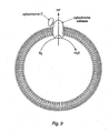
- Fig. 9 shows a membrane having cytochrome C, an enzyme, showing how functional systems may be created resembling cellular systems.
- Phospholipid gel-liquid-crystalline phase transition and the effect of cholesterol.
- Phospliolipids when fully hydrated, can exist in the gel, crystalline form (Lb) or in the fluid, liquid-crystalline state (La). In bilayers of gel state PC, the molecules can be packed such that the acyl chains are tilted with respect to the bilayer normal (Lb state).
- Raising the temperature converts the crystalline state into the liquid crystalline phase as detected by differential scanning calorimetry. For dipalmitoyl-PC the onset of the main transition occurs at approximately 41°C. The pretransition represents a small endothermic reorganization in the packing of the gel-state lipid molecules prior to melting.
- Table 3 shows the glass transition temperature for membranes formed of various compositions.
- Tc Temperature
- ⁇ H enthalpy
- Lipid Species a Tc ⁇ 2°C ⁇ H ⁇ 1 kcal/mol 12:0/12:0 PC b -1 3 14:0/14:0 PC 23 6 16:0/16:0 PC 41 8 16:0/18:1c ⁇ 9 PC -5 16:1c ⁇ 9 /18:1c ⁇ 9 PC -36 9 18:0/18:0 PC 54 18:1c ⁇ 9 /18:1c ⁇ 9 PC -20 9 16:0/16:0 PE 63 9 16:0/16:0 PS 55 9 16:0/16:0 PG 41 9 16:0/16:0 PA 67 5 a
- the code denotes the number of carbons per acyl chain and the number of double bonds.
- ⁇ gives the position of the double bond, c denotes cis .
- PC phosphatidylcholine; PE, phosphatidylethanolamine; PS, phosphatidylserine; PG, phosphatidylglycerol; PA, phosphatidic acid.
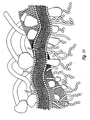
- Fig. 11 which is a schematic drawing of a cell membrane
- the membrane is normally composed of a relatively thin lipid bilayer into which larger protein molecules may be inserted.
- the proteins alter the microenvironment in the membrane, and thus modify the characteristics of the surrounding portion of the membrane, allowing local differences in properties, such as glass transition temperature, to exist.
- Edidin, M. "Molecular Motions and Membrane Organization and Function", Finean & Mitchell (eds.) Membrane Structure, Chapter 2, Elsevier (1981 ); Cullis, P. et al., “Physical Properties and Functional Roles of Lipids in Membranes", Vance et al.
- liposomes are endocytosed by macrophages or reticulo-endothelial cells, preventing fusion of the membranes. See, van Rooijen, N. et aL, "Transient Suppression of Macrophage Functions by liposome-encapsulated Drugs", TIBTECH, 15:178-185 (May 1997 ).
- RTCP treatment two membranes in close proximity may be excited and made unstable ("melted") to allow fusion.
- the type of changes which may occur in the membranes are shown schematically in Fig. 16 , along with an NMR tracing showing a change in chemical configuration.
- RTCP partial cellular permeability during treatment will also be apparent, but that the cells will return to normal after RTCP treatment. Excess RTCP treatment, however, may result in massive loss of membrane integrity and cell death. The treatment need not be lethal, and in fact it is believed that under some conditions RTCP may selectively stimulate or activate cells. In particular, cells which have become tolerant to a condition may be subject to "rejuvenation".
- the liposome is a synthetic structure, the exact composition and characteristics of a liposome may be engineered to assure efficient fusion, which occurs by a process as indicated in Fig. 17 .
- liposomes are endocytosed or "eaten” by cells of the reticuloendothelial system (RES), avoiding direct uptake of liposome contents and membrane fusion.
- RES reticuloendothelial system
- This fusion may be promoted by the use of "receptors" or antibodies which specifically attract the cell surfaces together, a technique particularly appropriate for vesicles or liposomes.
- receptors may be, for example, genetically engineered viral glycoproteins. Nonspecific absorption techniques may also be used.
- the fusion of a liposome with a cell may be used to alter the characteristics of a target cell, which may be a circulating blood cell, in vitro cell culture, biopsy cell sample, or the like.
- a target cell which may be a circulating blood cell, in vitro cell culture, biopsy cell sample, or the like.
- the surface of the cell is modified by the liposome-bound membrane proteins, while the contents of the liposome are released into the cell.
- a target cell which may be a circulating blood cell, in vitro cell culture, biopsy cell sample, or the like.
- the surface of the cell is modified by the liposome-bound membrane proteins, while the contents of the liposome are released into the cell.
- One or both of these principals may be applied in any given case.
- Liposomes which have been proposed as drug delivery systems alone, are rapidly and preferentially taken up by the reticulo-endothelial system, thus making them difficult to target to other organ systems.
- normal-appearing erythrocytes are not taken up by the reticulo-endothelial system, and may have an average circulating lifespan of 60 days.
- a long lasting reservoir of drug may be obtained.
- G6DH glycose-6-dehydrogenase deficiency
- this technology is not limited to erythrocyte disorders. Otherwise normal erythrocytes may be targeted to a particular tissue, for example by modifying the surface structures. This surface modification may be, for example, by liposomal membrane components.
- the modified erythrocytes need not be returned to the venous system, and may be presented thorough the lymphatic system or other body space. By using erythrocytes, or even the patient's own erythrocytes, rejection and side effects are minimized.
- a target disease for this type of treatment is chronic viral infection, such as hepatitis (hepatitis B, hepatitis C, delta factor) or AIDS.
- hepatitis hepatitis B, hepatitis C, delta factor
- AIDS chronic viral infection
- red blood cells are modified to present viral receptors. Due to the large number of red blood cells, the virus load is absorbed, tending to spare the normal target cells. The red blood cells are not capable of reproducing virus, ending the life cycle.
- a specific antiviral agent may be provided in the liposomes to further interfere with viral reproduction (in other cells).
- RTCP due to the potential for controlled heating effects and abrupt changes in temperature, has the potential to promote cell fusion. As stated above, this fusion may be symmetric between two cells or asymmetric between vesicles or liposomes and cells.
- the membrane structure of cells is difficult to control or modify.
- in vitro cell culture techniques including nutrient broth and incubation temperature, may be used to control membrane composition.
- receptors or antibodies may be used to align cells for fusion, typically a non-specific absorption technique might be applied to agglomerate cells prior to treatment.
- a typical application for fused cells is the production of monoclonal antibodies.
- a B-lymphocyte of a selected clone e.g., human antigen-specific
- an immortalized mouse cell line to produce an immortalized (continuously growing) cell line which produces a selected type of human immunoglobulin (hybridoma).
- a selected clone e.g., human antigen-specific
- an immortalized mouse cell line e.g., human antigen-specific
- a typical use of this technique is the production of tumor specific antibodies as a diagnostic or therapeutic agent.
- the antigens on the tumor may vary between patents with the same diagnosis, so that a large library of antibodies must be maintained or a custom production technique implemented.
- the RTCP technique may therefore be used to generate a large number of candidate clones, which may then be tested with the actual tumor cells and then cultured to produce significant quantities, all within a clinical timeframe.
- the patient's own lymphocytes may be used to produce the antibodies, potentially reducing an adverse or allergic response, and increasing the possibility of finding an appropriate clone, given the existing stimulation of the patient's immune system by the tumor.
- RTCP-induced cell fusion allows recombinant antigens to be presented on a desired cell type, for example erythrocytes, which may activate the body's cellular immune system to produce an effective response.
- a cell such as an erythrocyte or other sacrificial cell is modified to present a foreign antigen.
- the antigen may be, for example, gp120 (HIV), HBSag (Hepatitis B surface antigen), or other known antigens, not necessarily related to human disease or deficient vaccine response in humans.
- the antigen is provided by fusion of the sacrificial erythrocyte cell with an engineered liposome, as discussed above.
- an artificial cell may be constructed by fusing one or more engineered liposomes with a target, to produce a structure with only the desired antigenic determinants.
- Formed cells circulating through the blood include red blood cells (erythrocytes), white blood cells (leukocytes), platelets, metastatic and abnormal cells, viremia and bacteremia.
- the treatment with RTCP may be used to produce a number of different effects in populations and subpopulations of the cells. These treatments include killing or lysis, membrane disruption (reversible or irreversible), membrane component exchange with medium, other cells, or vesicles or liposomes, budding of cellular components, cell fusion or liposome-cell fusion, or other effects.
- the RTCP technology having millisecond temperature rise-times, disrupts or alters cell membranes and larger formed structures, while retaining protein configurations and thus avoids certain protein denaturation.
- this RTCP technique may be used to kill bacteria or some viruses in plasma or serum. This killing may be direct, by the known thermal shock mechanism, or by augmentation of MSP with membrane-active compositions which reduce membrane integrity and thus increase cell or virus lysis under the MSP conditions.
- Augmentors may include phosphatidylethanolmines, diacylglycerol, ethanol, short chain fatty acids, lipid peroxides, and other compositions. Some of these augmentors are innocuous, may be removed or degraded, or have desired or beneficial effects.
- treatment conditions may be established which are typically non-lethal for formed cell components, yet which temporarily reduce membrane integrity. This temporary lapse may allow cellular contents to leach into the extracellular fluid, allow extracellular reagents to enter the cell, or allow a reconstitution of the cell membrane with foreign proteins, lipids, drugs or macromolecules.
- red blood cells as a vehicle to provide a durable (approximate 60 day average life for a normal adult) reservoir or drug, while, depending on the particular drug, directing release into the liver and spleen or throughout the body.
- drugs might include contraceptive agents, flavinoids, steroids, carotenoids, markers and radionucleides, antifungal agents (amphotericin B), vitamin B-12, antioxidants, such as glutathione and alpha-tocopherol, and other compositions.
- the technique also holds promise for reformulating membranes of cells, for example inserting phosphatidyl choline or sphingomyelin, cholesterol in the membrane of erythrocytes, which may reduce uptake by the reticuloendothelial system. Likewise, the concentration of these composition may be reduced to target the RES. These techniques may also be applied to liposomes, although typically the membrane composition may be defined during production and need not be later altered.
- This technique may also offer hope for the treatment of certain diseases in which erythrocyte membrane chemistry is abnormal, for example resulting in fragile cells and excessive hemolysis.
- erythrocytes are treated to either exchange hemoglobin with a pool of normal hemoglobin (synthetic or from human or animal donors), or to access the intracellular space of the erythrocyte to change conditions (e.g., pH), to alter oxygen binding characteristics.
- conditions e.g., pH
- the technique may also be used to increase the shelf life of formed blood components, such as by the addition of antioxidants to the membrane or intracellular space, or even the introduction of enzymes necessary for vitality.
- the later may be effectively achieved by facilitated fusion of a cell with a liposome containing the desired membrane or cytoplasmic components.
- This technique also holds promise for gene therapy, in that genetic material may be introduced into cells without viral vectors.
- RTCP would not be expected to exert a selective effect on mammalian cells, so that a lethal treatment for one subclass would likely be lethal for the other subclasses.
- Two strategies are available to increase selectivity of effect, resulting in differential killing or processing.
- RTCP treatment This possible selectivity is based on the regional mosaic properties of cell membranes. various regions of cells have different glass transition temperatures, as well as mechanical responses to RTCP technology. In order to gain selectivity, the entire population of cells may be subjected to a treatment which selectively increases a response of a selected subgroup to the . RTCP treatment, or "hardens" a selected subgroup against RTCP treatment. These treatments thus seek to directly or indirectly selectively alter the lipid composition of cell membranes or the effect of RTCP on the membranes. Selectivity may ensured by simple metabolic distinction, mitogenic factors, other types of selective growth factors, monoclonal antibodies, drugs or hormones.
- the membrane lipid changes may be effected by altering the growth media while cell growth is selectively stimulated, fusing the selected cell populations with vesicles or liposomes of a desired composition, or employing native cellular mechanisms to alter the membrane composition. See, Horizons in Membrane Biotechnology (3 rd 1989), Progress in Clinical and Biological Research 343.
- While this technique is advantageously applied to circulating cells in the blood, it may also be applied to cells in culture or to cells from solid tissues which have been suspended.
- the alterations possible allow cellular "reprogramming", through external engineered additions to the cell structure. It is also conceivable to remove portions of the treated cells, such as membrane components having relatively lower transition temperatures. These cell changes may be temporary, for example the addition of exogenous receptors to cells. Thus, repeated treatments may be required to maintain a high level effect.
- the treatment may employ a plasmapheresis device or involve removal, treatment and reinfusion of cells into a patient.
- the cells are or are made differentially sensitive to the RTCP treatment.
- a selective effect is applied to a population of cells which are otherwise of equivalent sensitivity to RTCP treatment.
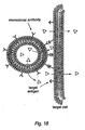
- vesicles or liposomes having receptors or monoclonal antibodies are mixed with unsorted cells and the mixture subjected to RTCP.
- the receptors or monoclonal antibodies interact selectively with certain cells, having complementary cell surface structures. This is shown schematically in Fig. 18 , in which the "Y" structures are specific antibodies against the arrow structures on the cell surface, and the triangular structures represent a specific treatment, which readily diffuses out of a liposome, being provided to the cell.
- RTCP technology allows fusion of the liposome membrane with the cellular membrane, so that the treatment is injected directly into the cell..
- the RTCP process raises the cell membranes to a temperature at which they begin to become unstable.
- the close proximity of the vesicles or liposomes with some cells causes a membrane fusion, which may be a physical effect or a cell mediated effect.
- the liposome contains either within its core or on its surface a desired treatment for the cell. This treatment may be, for example, lethal to the selected population, for example a cytotoxin, or membrane lytic agent, such as alpha cyclodextrin or certain cyclic peptides, a free radical promoter or inhibitor (See, Proc. Int. Symp.
- the RTCP technique has the ability to expose normally hidden antigens from prokaryotic and eukaryotic cells, and likely from membrane-bound viruses, to the extracellular media.
- the technique may find application in the production of vaccines or autovaccination of individuals through the processing of plasma in a plasmapheresis apparatus.
Landscapes
- Health & Medical Sciences (AREA)
- Genetics & Genomics (AREA)
- Life Sciences & Earth Sciences (AREA)
- Engineering & Computer Science (AREA)
- Organic Chemistry (AREA)
- Chemical & Material Sciences (AREA)
- Zoology (AREA)
- Wood Science & Technology (AREA)
- Bioinformatics & Cheminformatics (AREA)
- Biomedical Technology (AREA)
- Biotechnology (AREA)
- General Engineering & Computer Science (AREA)
- Microbiology (AREA)
- Biochemistry (AREA)
- General Health & Medical Sciences (AREA)
- Plant Pathology (AREA)
- Molecular Biology (AREA)
- Biophysics (AREA)
- Physics & Mathematics (AREA)
- Apparatus For Disinfection Or Sterilisation (AREA)
- Saccharide Compounds (AREA)
- Physical Or Chemical Processes And Apparatus (AREA)
- Medicinal Preparation (AREA)
- Medicines Containing Material From Animals Or Micro-Organisms (AREA)
- Control Of Combustion (AREA)
- Separation Using Semi-Permeable Membranes (AREA)
Claims (8)
- In-Vitro-Verfahren für eine Zell-Zell-Fusion oder Zell-Liposom-Fusion, das den Schritt eines Unterwerfens einer Probe von Zellen oder einer Probe von Zellen (einer Zelle) und Liposomen (eines Liposoms) einem schnellen thermischen, zyklischen Behandlungsschritt in einem flüssigen Medium aufweist, wobei das flüssige Medium, das die Zellen oder die Zellen (die Zelle) und die Liposomen (das Liposom) enthält, unter einer Heiztemperatur-Anstiegsrate erwärmt wird, die 1000°C pro Sekunde übersteigt, und wobei der Anstieg der Erwärmungstemperatur geringer als 40°C ist und wobei die maximale Erwärmungstemperatur geringer als ungefähr 55°C ist, so dass ein Übergang einer Lipid-Doppelschicht zu einer Nicht-Doppelschicht in einem Bereich der Zellen oder der Zellen (der Zelle) und der Liposomen (des Liposoms) induziert wird, ohne die Zellen oder die Zellen (die Zelle) und die Liposomen (das Liposom) zu lysieren.
- Verfahren nach Anspruch 1, wobei die Zelle eine prokaryotische Zelle oder eine eukaryotische Zelle ist.
- Verfahren nach Anspruch 1 oder 2, wobei die Zelle aus der Gruppe ausgewählt ist, die aus einem Erythrozyt und einem Lymphozyt besteht.
- Verfahren nach Anspruch 2 oder 3, wobei die Zelle eine differenzierte Zelle ist, die ein spezifisches, definiertes sekretorische Genprodukt besitzt.
- Verfahren nach Anspruch 1, wobei die Zelle eine lebende Zelle ist.
- Verfahren nach Anspruch 1, wobei das Erwärmen nicht wesentlich Proteine der Zellen (der Zelle) oder der Liposomen (des Liposoms) denaturiert.
- Verfahren nach Anspruch 1, wobei das Erwärmen durch einen Kontakt des Mediums mit Dampf erreicht wird.
- Verfahren nach Anspruch 1, wobei das Medium vor einem Erwärmen zerstäubt wird.
Applications Claiming Priority (3)
| Application Number | Priority Date | Filing Date | Title |
|---|---|---|---|
| US6069097P | 1997-09-23 | 1997-09-23 | |
| US60690P | 1997-09-23 | ||
| PCT/US1998/019815 WO1999015638A1 (en) | 1997-09-23 | 1998-09-23 | Rapid thermal cycle processing methods and apparatus |
Publications (3)
| Publication Number | Publication Date |
|---|---|
| EP1015571A1 EP1015571A1 (de) | 2000-07-05 |
| EP1015571A4 EP1015571A4 (de) | 2003-07-16 |
| EP1015571B1 true EP1015571B1 (de) | 2009-04-22 |
Family
ID=22031160
Family Applications (1)
| Application Number | Title | Priority Date | Filing Date |
|---|---|---|---|
| EP98951925A Expired - Lifetime EP1015571B1 (de) | 1997-09-23 | 1998-09-23 | Verfahren und vorrichtung für schnelle thermozyklen |
Country Status (8)
| Country | Link |
|---|---|
| US (3) | US6277610B1 (de) |
| EP (1) | EP1015571B1 (de) |
| AT (1) | ATE429491T1 (de) |
| AU (1) | AU9775398A (de) |
| CA (1) | CA2303399A1 (de) |
| DE (1) | DE69840776D1 (de) |
| IL (1) | IL135125A0 (de) |
| WO (1) | WO1999015638A1 (de) |
Families Citing this family (26)
| Publication number | Priority date | Publication date | Assignee | Title |
|---|---|---|---|---|
| WO1999015638A1 (en) * | 1997-09-23 | 1999-04-01 | Ib2, L.L.C. | Rapid thermal cycle processing methods and apparatus |
| US7625584B2 (en) * | 2000-11-30 | 2009-12-01 | The Research Foundation Of State University Of New York | Method of complexing a protein by the use of a dispersed system and proteins thereof |
| US6646241B1 (en) * | 2002-02-08 | 2003-11-11 | Ecofriend Technologies, Inc. | Microwave-assisted steam sterilization of dental and surgical instruments |
| CA2476551A1 (en) * | 2002-02-15 | 2003-10-16 | Cygene, Inc. | Methods and compositions for in vivo clearance of pathogens |
| WO2003106695A2 (en) * | 2002-06-13 | 2003-12-24 | Cygene, Inc. | Methods and compositions for in vivo clearance of pathogens |
| WO2004087894A2 (en) * | 2003-04-01 | 2004-10-14 | S.C.Johnson & Son, Inc. | Bacterial aggregates |
| US7101691B2 (en) * | 2003-08-29 | 2006-09-05 | Ultraforce Technology Llc | Alcohol production using sonication |
| US7504245B2 (en) * | 2003-10-03 | 2009-03-17 | Fcstone Carbon, Llc | Biomass conversion to alcohol using ultrasonic energy |
| WO2005058378A1 (en) * | 2003-12-12 | 2005-06-30 | Charm Sciences, Inc. | Method, device and system for thermal processing |
| US7159407B2 (en) * | 2004-06-09 | 2007-01-09 | Chen Kuo-Mei | Atomized liquid jet refrigeration system |
| CN100389836C (zh) * | 2004-12-10 | 2008-05-28 | 北京市红十字血液中心 | B→o血型转换密闭式处理用四联袋及其使用方法 |
| FR2894830B1 (fr) * | 2005-12-19 | 2008-04-04 | Lab Francais Du Fractionnement | Procede d'inactivation virale par chauffage a sec selon la temperature de transition vitreuse |
| AU2007205898A1 (en) * | 2006-01-18 | 2007-07-26 | James S. Brophy | System for making products with improved particle morphology and particle distribution and products |
| EP2035836B1 (de) * | 2006-07-03 | 2013-02-27 | Thermo Finnigan LLC | Vorrichtung zur behandlung von vollblut für die bestimmung von analyten |
| US8241576B2 (en) | 2007-07-13 | 2012-08-14 | Oleg Rozenberg | Microbial inactivation by multiple pressure spikes delivered with regulated frequency |
| US9474301B2 (en) * | 2008-10-27 | 2016-10-25 | Cavitation Technologies, Inc. | Flow-through cavitation-assisted rapid modification of beverage fluids |
| WO2010114901A1 (en) | 2009-03-31 | 2010-10-07 | The Board Of Trustees Of The University Of Arkansas | Method of controlled drug release from a liposome carrier |
| US9599407B2 (en) | 2009-07-29 | 2017-03-21 | Tokitae Llc | System and structure for heating or sterilizing a liquid stream |
| US8425965B2 (en) | 2009-07-29 | 2013-04-23 | Tokitae Llc | Method for heating or sterilizing a liquid stream |
| US9930898B2 (en) | 2009-07-29 | 2018-04-03 | Tokitae Llc | Pasteurization system and method |
| JP5540209B2 (ja) * | 2009-11-17 | 2014-07-02 | 独立行政法人農業・食品産業技術総合研究機構 | 加熱媒体発生方法 |
| EP2776013B8 (de) | 2011-11-08 | 2023-08-30 | The Board of Trustees of the University of Arkansas | Verfahren und zusammensetzungen zur röntgeninduzierten freisetzung ph-empfindlicher liposome |
| ITMI20122195A1 (it) | 2012-12-20 | 2014-06-21 | Eni Spa | Metodo per il recupero di componenti intracellulari da microorganismi fermentati |
| US9281039B2 (en) | 2013-07-30 | 2016-03-08 | Qualcomm Incorporated | System and method to provide a reference cell using magnetic tunnel junction cells |
| US10674751B1 (en) | 2019-02-21 | 2020-06-09 | Empirical Innovations, Inc. | Heating medium injectors and injection methods for heating foodstuffs |
| CN117682899B (zh) * | 2024-01-30 | 2024-04-16 | 云南省林业和草原科学院 | 一种油橄榄果渣发酵设备 |
Family Cites Families (6)
| Publication number | Priority date | Publication date | Assignee | Title |
|---|---|---|---|---|
| US4975246A (en) * | 1985-09-30 | 1990-12-04 | Charm Stanley E | High temperature, short time heating system and method of heating heat-sensitive material |
| WO1990015594A1 (en) * | 1989-06-16 | 1990-12-27 | Liburdy, Robert, P. | Electromagnetic field triggered drug and chemical delivery via liposomes |
| RU2052967C1 (ru) * | 1993-03-04 | 1996-01-27 | Логинов Николай Иванович | Способ тепловой обработки жидких продуктов |
| US5389335A (en) * | 1993-06-18 | 1995-02-14 | Charm Sciences, Inc. | High temperature, short time microwave heating system and method of heating heat-sensitive material |
| AU2326297A (en) * | 1996-03-06 | 1997-09-22 | I. Belloch Corporation | Method for treating liquid materials |
| WO1999015638A1 (en) * | 1997-09-23 | 1999-04-01 | Ib2, L.L.C. | Rapid thermal cycle processing methods and apparatus |
-
1998
- 1998-09-23 WO PCT/US1998/019815 patent/WO1999015638A1/en active Application Filing
- 1998-09-23 AU AU97753/98A patent/AU9775398A/en not_active Abandoned
- 1998-09-23 CA CA002303399A patent/CA2303399A1/en not_active Abandoned
- 1998-09-23 EP EP98951925A patent/EP1015571B1/de not_active Expired - Lifetime
- 1998-09-23 IL IL13512598A patent/IL135125A0/xx unknown
- 1998-09-23 AT AT98951925T patent/ATE429491T1/de not_active IP Right Cessation
- 1998-09-23 US US09/508,889 patent/US6277610B1/en not_active Expired - Lifetime
- 1998-09-23 DE DE69840776T patent/DE69840776D1/de not_active Expired - Fee Related
-
2001
- 2001-08-17 US US09/931,827 patent/US6579706B2/en not_active Expired - Lifetime
-
2003
- 2003-06-17 US US10/462,939 patent/US7449314B2/en not_active Expired - Fee Related
Also Published As
| Publication number | Publication date |
|---|---|
| WO1999015638A1 (en) | 1999-04-01 |
| US20040023351A1 (en) | 2004-02-05 |
| US7449314B2 (en) | 2008-11-11 |
| DE69840776D1 (de) | 2009-06-04 |
| WO1999015638B1 (en) | 1999-06-03 |
| US6277610B1 (en) | 2001-08-21 |
| EP1015571A1 (de) | 2000-07-05 |
| EP1015571A4 (de) | 2003-07-16 |
| ATE429491T1 (de) | 2009-05-15 |
| US6579706B2 (en) | 2003-06-17 |
| US20020168734A1 (en) | 2002-11-14 |
| CA2303399A1 (en) | 1999-04-01 |
| AU9775398A (en) | 1999-04-12 |
| IL135125A0 (en) | 2001-05-20 |
Similar Documents
| Publication | Publication Date | Title |
|---|---|---|
| EP1015571B1 (de) | Verfahren und vorrichtung für schnelle thermozyklen | |
| CA2247860C (en) | Method for treating liquid materials | |
| EP0882448B1 (de) | Verfahren zur Verkapselung von biologisch aktiven Stoffen in Erythrocyten und Gerät dafür | |
| US10273444B2 (en) | Lysis/resealing process and device for incorporating an active ingredient, in particular asparaginase or inositol hexaphosphate, in erythrocytes | |
| KR0162094B1 (ko) | 혈소판 막 미립자 | |
| US11413252B2 (en) | Membrane lipid coated viral nanoparticles and method of use | |
| EP3999116A1 (de) | Verfahren zur herstellung von mit membranlipid beschichteten nanopartikeln | |
| US11471420B2 (en) | Membrane lipid coated nanoparticles and method of use | |
| Barren et al. | A method for preparing chromosomes from peripheral blood of the mouse | |
| Weissmann | The Introduction of Missing Enzymes into Human Cells: Alternatives to DNA Recombinancy in Genetic Disease | |
| blood cell Dialysis | Erythrocyte Encapsulation as a novel drug delivery system in cancer treatment | |
| CN117860698A (zh) | 靶向肿瘤组织的卡介苗融合囊泡及其制备方法与应用 | |
| Furusawa et al. | Use of Erythrocyte Ghosts for Therapy |
Legal Events
| Date | Code | Title | Description |
|---|---|---|---|
| PUAI | Public reference made under article 153(3) epc to a published international application that has entered the european phase |
Free format text: ORIGINAL CODE: 0009012 |
|
| 17P | Request for examination filed |
Effective date: 20000322 |
|
| AK | Designated contracting states |
Kind code of ref document: A1 Designated state(s): AT BE CH DE DK ES FI FR GB GR IE IT LI NL PT SE |
|
| A4 | Supplementary search report drawn up and despatched |
Effective date: 20030603 |
|
| RIC1 | Information provided on ipc code assigned before grant |
Ipc: 7A 61L 2/06 B Ipc: 7C 12N 15/88 B Ipc: 7C 12N 13/00 A |
|
| 17Q | First examination report despatched |
Effective date: 20030826 |
|
| GRAP | Despatch of communication of intention to grant a patent |
Free format text: ORIGINAL CODE: EPIDOSNIGR1 |
|
| GRAS | Grant fee paid |
Free format text: ORIGINAL CODE: EPIDOSNIGR3 |
|
| GRAA | (expected) grant |
Free format text: ORIGINAL CODE: 0009210 |
|
| AK | Designated contracting states |
Kind code of ref document: B1 Designated state(s): AT BE CH DE DK ES FI FR GB GR IE IT LI NL PT SE |
|
| REG | Reference to a national code |
Ref country code: GB Ref legal event code: FG4D |
|
| REG | Reference to a national code |
Ref country code: CH Ref legal event code: EP |
|
| REG | Reference to a national code |
Ref country code: IE Ref legal event code: FG4D |
|
| REF | Corresponds to: |
Ref document number: 69840776 Country of ref document: DE Date of ref document: 20090604 Kind code of ref document: P |
|
| NLV1 | Nl: lapsed or annulled due to failure to fulfill the requirements of art. 29p and 29m of the patents act | ||
| PG25 | Lapsed in a contracting state [announced via postgrant information from national office to epo] |
Ref country code: PT Free format text: LAPSE BECAUSE OF FAILURE TO SUBMIT A TRANSLATION OF THE DESCRIPTION OR TO PAY THE FEE WITHIN THE PRESCRIBED TIME-LIMIT Effective date: 20090822 Ref country code: FI Free format text: LAPSE BECAUSE OF FAILURE TO SUBMIT A TRANSLATION OF THE DESCRIPTION OR TO PAY THE FEE WITHIN THE PRESCRIBED TIME-LIMIT Effective date: 20090422 Ref country code: ES Free format text: LAPSE BECAUSE OF FAILURE TO SUBMIT A TRANSLATION OF THE DESCRIPTION OR TO PAY THE FEE WITHIN THE PRESCRIBED TIME-LIMIT Effective date: 20090802 Ref country code: AT Free format text: LAPSE BECAUSE OF FAILURE TO SUBMIT A TRANSLATION OF THE DESCRIPTION OR TO PAY THE FEE WITHIN THE PRESCRIBED TIME-LIMIT Effective date: 20090422 |
|
| PG25 | Lapsed in a contracting state [announced via postgrant information from national office to epo] |
Ref country code: SE Free format text: LAPSE BECAUSE OF FAILURE TO SUBMIT A TRANSLATION OF THE DESCRIPTION OR TO PAY THE FEE WITHIN THE PRESCRIBED TIME-LIMIT Effective date: 20090722 Ref country code: NL Free format text: LAPSE BECAUSE OF FAILURE TO SUBMIT A TRANSLATION OF THE DESCRIPTION OR TO PAY THE FEE WITHIN THE PRESCRIBED TIME-LIMIT Effective date: 20090422 |
|
| PG25 | Lapsed in a contracting state [announced via postgrant information from national office to epo] |
Ref country code: DK Free format text: LAPSE BECAUSE OF FAILURE TO SUBMIT A TRANSLATION OF THE DESCRIPTION OR TO PAY THE FEE WITHIN THE PRESCRIBED TIME-LIMIT Effective date: 20090422 |
|
| PG25 | Lapsed in a contracting state [announced via postgrant information from national office to epo] |
Ref country code: BE Free format text: LAPSE BECAUSE OF FAILURE TO SUBMIT A TRANSLATION OF THE DESCRIPTION OR TO PAY THE FEE WITHIN THE PRESCRIBED TIME-LIMIT Effective date: 20090422 |
|
| PLBE | No opposition filed within time limit |
Free format text: ORIGINAL CODE: 0009261 |
|
| STAA | Information on the status of an ep patent application or granted ep patent |
Free format text: STATUS: NO OPPOSITION FILED WITHIN TIME LIMIT |
|
| 26N | No opposition filed |
Effective date: 20100125 |
|
| REG | Reference to a national code |
Ref country code: CH Ref legal event code: PL |
|
| GBPC | Gb: european patent ceased through non-payment of renewal fee |
Effective date: 20090923 |
|
| REG | Reference to a national code |
Ref country code: IE Ref legal event code: MM4A |
|
| REG | Reference to a national code |
Ref country code: FR Ref legal event code: ST Effective date: 20100531 |
|
| PG25 | Lapsed in a contracting state [announced via postgrant information from national office to epo] |
Ref country code: IE Free format text: LAPSE BECAUSE OF NON-PAYMENT OF DUE FEES Effective date: 20090923 Ref country code: FR Free format text: LAPSE BECAUSE OF NON-PAYMENT OF DUE FEES Effective date: 20090930 Ref country code: DE Free format text: LAPSE BECAUSE OF NON-PAYMENT OF DUE FEES Effective date: 20100401 |
|
| PG25 | Lapsed in a contracting state [announced via postgrant information from national office to epo] |
Ref country code: LI Free format text: LAPSE BECAUSE OF NON-PAYMENT OF DUE FEES Effective date: 20090930 Ref country code: GR Free format text: LAPSE BECAUSE OF FAILURE TO SUBMIT A TRANSLATION OF THE DESCRIPTION OR TO PAY THE FEE WITHIN THE PRESCRIBED TIME-LIMIT Effective date: 20090723 Ref country code: CH Free format text: LAPSE BECAUSE OF NON-PAYMENT OF DUE FEES Effective date: 20090930 |
|
| PG25 | Lapsed in a contracting state [announced via postgrant information from national office to epo] |
Ref country code: GB Free format text: LAPSE BECAUSE OF NON-PAYMENT OF DUE FEES Effective date: 20090923 |
|
| PG25 | Lapsed in a contracting state [announced via postgrant information from national office to epo] |
Ref country code: IT Free format text: LAPSE BECAUSE OF FAILURE TO SUBMIT A TRANSLATION OF THE DESCRIPTION OR TO PAY THE FEE WITHIN THE PRESCRIBED TIME-LIMIT Effective date: 20090422 |