EP1014691A2 - Système de traitement d'images pour réduire les motifs verticaux sur des images balayées - Google Patents
Système de traitement d'images pour réduire les motifs verticaux sur des images balayées Download PDFInfo
- Publication number
- EP1014691A2 EP1014691A2 EP99203957A EP99203957A EP1014691A2 EP 1014691 A2 EP1014691 A2 EP 1014691A2 EP 99203957 A EP99203957 A EP 99203957A EP 99203957 A EP99203957 A EP 99203957A EP 1014691 A2 EP1014691 A2 EP 1014691A2
- Authority
- EP
- European Patent Office
- Prior art keywords
- image
- map
- binary
- binary images
- vertically disposed
- Prior art date
- Legal status (The legal status is an assumption and is not a legal conclusion. Google has not performed a legal analysis and makes no representation as to the accuracy of the status listed.)
- Granted
Links
Images


Classifications
-
- H—ELECTRICITY
- H04—ELECTRIC COMMUNICATION TECHNIQUE
- H04N—PICTORIAL COMMUNICATION, e.g. TELEVISION
- H04N1/00—Scanning, transmission or reproduction of documents or the like, e.g. facsimile transmission; Details thereof
- H04N1/40—Picture signal circuits
- H04N1/409—Edge or detail enhancement; Noise or error suppression
- H04N1/4097—Removing errors due external factors, e.g. dust, scratches
Definitions
- the present invention relates to an image processing system which removes vertical artifacts such as lines on images produced by scanning an original document, without loss of image information.
- An object of the present invention is to provide for a digital image processing method which identifies vertically disposed patterns or artifacts caused by dirty image guides in scanners and then subtracts the vertically disposed patterns before creating the final image of the scanned document.
- the vertically disposed patterns can be in the form of lines, dashes, dots, etc.
- the present invention provides for a digital image processing method which includes the steps of (1) applying an edge-based adaptive thresholding method twice with different contrast parameter settings to convert an image such as a gray scale image into two binary images; (2) generating a map of the difference from the two binary images; (3) projecting the vertical profile of the map; (4) detecting the local peaks, (i.e. vertical lines, dashes, dots, etc.) from the vertical projection profile; (5) locating the regions of the vertical lines, dashes, dots, etc. in the map based on the detected local peaks; and (6) reversing pixels from the binary images based on the vertical lines, dashes, dots, etc. of the map.
- an edge-based adaptive thresholding method twice with different contrast parameter settings to convert an image such as a gray scale image into two binary images
- generating a map of the difference from the two binary images (3) projecting the vertical profile of the map
- the method of the present invention includes: capturing a document image by a CCD array in raster scan fashion; applying an edge-based adaptive thresholding technique[1] with a normal contrast setting to extract every detail of image information and storing the resulting binary image, named as B1; applying the same edge-based adaptive thresholding technique with a low contrast setting which only extracts high contrast details of the image, named as B2; labelling the difference of B1 and B2, and storing the map of the difference, named as D; projecting the vertical profile of the map (D); locating the vertically disposed patterns by detecting the local peaks in the vertical projection profile, resulting in a map of the vertically disposed patterns, named as V; reading the binary image (B1) and the map of the vertically disposed patterns (V); and reversing pixels in the B1 image at the corresponding black pixel locations in the V map.
- the present invention provides for an image processing method which comprises the steps of: converting an image into first and second binary images; comparing the first and second binary images and generating a map indicative of a difference between the first and second binary images; projecting a vertical profile of the map and detecting peaks in the vertical profile; locating regions of vertically disposed patterns in the map based on the detected peaks; and reversing pixels from the first binary image based on the vertically disposed patterns in the map.
- the present invention further relates to an image processing method which comprises the steps of: capturing an image; extracting image information from the image and storing a resulting image as a first binary image; extracting high contrast details from the image and storing a resulting image as a second binary image; comparing the first and second binary images and generating a bitmap indicative of a difference between the first and second binary images; projecting a vertical profile of the bitmap; locating regions of vertically disposed patterns in the bitmap by detecting local peaks in the vertical profile so as to provide for a map of vertically disposed patterns; and reversing pixels from the first binary image based on the vertically disposed patterns of the map.
- the present invention further relates to an image processing method which comprises the steps of: converting an image into first and second binary images; generating a map indicative of a difference between the first and second binary images; and reversing pixels from the first binary image based on vertically disposed patterns in said map.
- the present invention further relates to an image capture assembly that comprises an image capture section which captures an image; a conversion section which converts the captured image into digital image information indicative of the captured image; and a processing section which receives the digital information and converts the captured image into first and second binary images.
- the processing section compares the first and second binary images to generate a map indicative of a difference between the first and second binary images and reverses pixels from the first binary image based on vertically disposed patterns in the map.
- FIG. 1A a block diagram of an image processing method that performs an image thresholding with minimal vertical line artifacts is shown in Figure 1A.
- the method and assembly of the present invention will be described with respect to vertical lines, however, it is recognized that the present invention is not limited to the removal of lines.
- the present invention is applicable to removing or reducing vertically disposed visual patterns or artifacts such as lines, dashes, dots, marks and any combination thereof.
- an image such as digital gray scale image data (G) is received as input (step 7), and the method operates as follows: (1) An edge-based image thresholding is first applied (step 9) to convert the grey scale image (G) into a binary image (B1) with normal contrast parameter setting which extracts full details of image information; (2) The edge-based image thresholding is applied again (step 11) to convert the grey scale image (G) into another binary image (B2) with low contrast parameter setting which only extracts dark high-contrast objects; (3) The two binary images, (B1) and (B2), are compared pixel-by-pixel (step 15), identifying a pixel as a "black” pixel if there is a difference and a "white” pixel if there is no difference, to generate a map of the difference, named as (D), between the two binary images (B1) and (B2); (4) The vertical visual artifacts such as vertical lines in the map (D) are located (step 17) by doing a vertical projection profile analysis which
- FIG. 1B shows a schematic illustration of an image capture assembly 300 which processes captured images in accordance with the described features of the present invention.
- Image capture assembly 300 can be a scanner which includes an image capture section 301 in the form of, for example, a charge coupled device that captures an image, and a conversion section 303 in the form of, for example, an A/D converter which converts the captured image into digital information indicative of the captured image.
- the digital information is sent to a processing section 305 which processes the digital image information as described with reference to Figure 1A, and as will be further described with reference to Figures 2A, 3A, 4A and 5A.
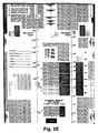
- FIG. 2A is block diagram of an image processing system that performs the edge-based adaptive thresholding.
- the thresholding method receives as input the digital image from a scanner and operator specified input parameters IT (intensity threshold) and GT (gradient threshold) and includes the following steps:
- Sobel gradient operator is applied to the image intensity record to produce a gradient strength record (step 21).
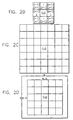
- the Sobel operator works on a 3-by-3 window of pixels, as shown in Figure 2B, to compute the horizontal and vertical intensity gradients, GX(i, j) and GY(i, j) at pixel position (i, j).
- the gradient strength GS(i, j) at pixel position (i, j) is the absolute sum of the horizontal and vertical intensity gradients, GX(i, j) and GY(i, j) respectively.
- the minimal intensity - Lmin(i, j) and maximal intensity - Lmax(i, j) in a N-by-N window are measured (step 27) from the image intensity record as shown in Fig. 2C and the sum of gradient strength GS (i, j) in a (N-2)-by-(N-2) window, as shown in Figure 2D, is calculated from the gradient strength (step 23 of Figure 2A).
- the sum of gradient GS (i, j) is defined as an area gradient.
- the three feature values GS (i, j), Lmin (i, j), Lmax (i, j) are used for classifying the pixel at (i, j) into black or white in the image intensity record.
- the final process is the extraction of black pixels (objects).
- the first step of extraction is the detection of pixels near an edge. A pixel at (i, j) near an edge is confirmed whenever the area gradient is high and larger than a predetermined value - a gradient threshold (GT) (step 25). After a pixel near an edge is found the pixel (the center pixel of the local window) is classified as black (object) when its intensity is smaller than the average of Lmin(i, j) and Lmax(i, j) (steps 29 and 30). That is, it is in the darker side of an edge.
- GT gradient threshold
- the classification is then made by a simple thresholding. That is comparing the gray value of the pixel with another predetermined intensity threshold value (IT). If the gray value of a pixel is smaller than IT, the pixel is classified as black; otherwise it is treated as white background (step 33).
- the image quality after thresholding by the technique is controlled by the user's selection of the two threshold (GT and IT) settings.
- the GT is set for classifying pixels in the vicinity of edges and the IT is then set for classifying pixels in uniform regions.
- a low GT setting tends to extract edge pixels of light objects and a low IT setting inclines to classify pixels of a gray uniform region into white background.
- the algorithm acts just like a fixed thresholding with threshold setting at IT. Since under this situation GT is always larger than the area gradient, the pixel classification of the image as shown in Fig. 2A is solely determined by comparing IT with the intensity at the pixel of interest.
- the technique can also produce an outline image by simply setting the IT to zero in which all pixels classify as white except the edge pixels where area gradients are larger than GT.
- Figure 2E An example of a captured grey scale document image using a production scanner is shown in Figure 2E. A few light vertical line image artifacts 50 are observed.
- Figure 2F is the thresholded image obtained by applying the edge-based thresholding technique with a normal contrast setting to the grey scale image in Figure 2E. Since the image thresholding with a normal contrast setting attempts to extract every details of image information in the grey scale image, it also turns the unwanted, light vertical lines into vertical black lines 50'. In the case of a low contrast setting, the light contrast objects such as the light vertical lines, light characters and any light objects are ignored in the thresholding process and they are not exhibited in the thresholded image as shown in Figure 2G.
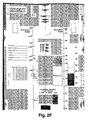
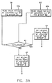
- Figure 3A is a block diagram of generating a map of the image difference between the two thresholded images B1 and B2 of Figure 1.
- a bitmap value B1(i, j) which is either 1 (black) or 1 (white) at location (i, j) of the image B1 is read (step 40a), and a bitmap value B2 (i, j) at the corresponding location (i, j) of the image B2 is also read (step 40b).
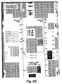
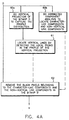
- Figure 4A is a block diagram of generating a map of vertical lines.
- the generation of vertical lines is made by projecting a vertical profile of the map D (step 60a), and by doing standard connected component analysis (2) to locate character-like components and non-vertical line components (step 60b).
- the vertical, projection, profile is the frequency distribution of black pixels in a one dimensional plane. It allows one to easily locate the vertical lines by detecting the peaks in the one-dimensional frequency distribution (step 61).
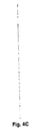
- An example of the vertical projection profile of the map in Figure 3B is shown in Figure 4B.
- the multiple peaks in Figure 4B indicates that there are multiple vertical lines appearing in the map D.
- the locations of the peaks are detected by comparing the value of every location with a certain threshold.
- the peaks whose values are larger than the threshold are considered as locations of lines.
- a connected component analysis is applied to extract connected components from the map D (see, for example, USSN 08/739,076). Every connected component represents an object.
- An object means a character, a graphics, a line, or even noises.
- a size threshold or its aspect ratio (height/width) is greater than an aspect threshold value, the object is considered as part of the image.
- the black pixels associated with the object are deleted from the map D (step 62).
- the map of vertical lines is derived from the combination of component analysis and vertical projection profile.
- the component analysis removes the black pixels of image information from the map D, and the vertical projection profile locates the vertical lines that are considered light vertical lines which are generated by pieces of dirt or dust.
- the map D in Figure 3B is converted into a vertical line map as shown Figure 4C.
- Figure 5A is a block diagram of the vertical pattern or artifact removal process which will be described with respect to a vertical line removal but is applicable to the removal of dashes, dots, etc.
- the bitmap value b1 (i, j) at location (i, j) in the image B1 is read, and the bitmap value v (i, j) at the corresponding location (i, j) in the bitmap V is also read (step 70). If the value v (i, j) is marked as "1", where "1" indicates black and "0" indicates white (step 71), then the value b1 (i, j) is examined (step 72).
- bitmap B is a copy of bitmap B1 after vertical line removal, where b(i, j) is the value of the bitmap B at location (i, j).
- Figure 5B is an example of the final thresholded image in which the vertical line artifacts are removed from the bitmap in Figure 2E.
Landscapes
- Engineering & Computer Science (AREA)
- Multimedia (AREA)
- Signal Processing (AREA)
- Facsimile Image Signal Circuits (AREA)
- Image Processing (AREA)
- Image Analysis (AREA)
- Apparatus For Radiation Diagnosis (AREA)
Applications Claiming Priority (2)
| Application Number | Priority Date | Filing Date | Title |
|---|---|---|---|
| US211600 | 1998-12-14 | ||
| US09/211,600 US6317223B1 (en) | 1998-12-14 | 1998-12-14 | Image processing system for reducing vertically disposed patterns on images produced by scanning |
Publications (3)
| Publication Number | Publication Date |
|---|---|
| EP1014691A2 true EP1014691A2 (fr) | 2000-06-28 |
| EP1014691A3 EP1014691A3 (fr) | 2002-05-15 |
| EP1014691B1 EP1014691B1 (fr) | 2005-05-18 |
Family
ID=22787596
Family Applications (1)
| Application Number | Title | Priority Date | Filing Date |
|---|---|---|---|
| EP99203957A Expired - Lifetime EP1014691B1 (fr) | 1998-12-14 | 1999-11-25 | Système de traitement d'images pour réduire les motifs verticaux sur des images balayées |
Country Status (4)
| Country | Link |
|---|---|
| US (1) | US6317223B1 (fr) |
| EP (1) | EP1014691B1 (fr) |
| JP (1) | JP4334712B2 (fr) |
| DE (1) | DE69925354T2 (fr) |
Cited By (3)
| Publication number | Priority date | Publication date | Assignee | Title |
|---|---|---|---|---|
| US6317223B1 (en) * | 1998-12-14 | 2001-11-13 | Eastman Kodak Company | Image processing system for reducing vertically disposed patterns on images produced by scanning |
| EP1558018A3 (fr) * | 2004-01-26 | 2006-06-28 | Ricoh Company, Ltd. | Dispositif de lecture de document et dispositif de formation d'image correspondant |
| CN115578729A (zh) * | 2022-11-21 | 2023-01-06 | 国网浙江省电力有限公司信息通信分公司 | 数字员工ai智能流程编排方法 |
Families Citing this family (19)
| Publication number | Priority date | Publication date | Assignee | Title |
|---|---|---|---|---|
| US6870959B1 (en) * | 1999-10-07 | 2005-03-22 | Hewlett-Packard Development Company, L.P. | Method for automatic removal of vertical streaks by modifying image data associated with non-homogenous image elements |
| JP2002077625A (ja) * | 2000-08-30 | 2002-03-15 | Minolta Co Ltd | 画像処理装置、画像処理方法および画像処理プログラムを記録したコンピュータ読取可能な記録媒体 |
| US6822766B2 (en) * | 2001-03-01 | 2004-11-23 | Hewlett-Packard Development Company, L.P. | Correction for debris and low output photosensors in scroll fed scanner using stored initial calibration data |
| US7031543B2 (en) * | 2002-01-02 | 2006-04-18 | Xerox Corporation | Grayscale image de-speckle algorithm |
| US6947607B2 (en) | 2002-01-04 | 2005-09-20 | Warner Bros. Entertainment Inc. | Reduction of differential resolution of separations |
| US7092584B2 (en) * | 2002-01-04 | 2006-08-15 | Time Warner Entertainment Company Lp | Registration of separations |
| US6873728B2 (en) * | 2002-01-16 | 2005-03-29 | Eastman Kodak Company | Vertical black line removal implementation |
| FR2841487B1 (fr) * | 2002-06-26 | 2004-08-20 | Solystic | Procede de detection de plis simples et de plis en prise multiple dans une installation de tri postal |
| ITRM20040563A1 (it) * | 2004-11-12 | 2005-02-12 | St Microelectronics Srl | Metodo di elaborazione di un'immagine digitale. |
| US7620241B2 (en) * | 2004-11-30 | 2009-11-17 | Hewlett-Packard Development Company, L.P. | Artifact reduction in a digital video |
| US8358452B2 (en) * | 2005-05-27 | 2013-01-22 | Hewlett-Packard Development Company | Imaging system and method |
| US7973977B2 (en) * | 2007-05-18 | 2011-07-05 | Reliance Media Works | System and method for removing semi-transparent artifacts from digital images caused by contaminants in the camera's optical path |
| US9241128B2 (en) | 2013-02-14 | 2016-01-19 | Warner Bros. Entertainment Inc. | Video conversion technology |
| JP2014200062A (ja) * | 2013-03-14 | 2014-10-23 | 株式会社リコー | 画像読取装置及び縦スジ判定方法 |
| CN104517089B (zh) * | 2013-09-29 | 2017-09-26 | 北大方正集团有限公司 | 一种二维码解码系统及其方法 |
| GB2547220A (en) | 2016-02-10 | 2017-08-16 | Testplant Europe Ltd | Method of, and apparatus for, testing computer hardware and software |
| GB2547222A (en) | 2016-02-10 | 2017-08-16 | Testplant Europe Ltd | Method of, and apparatus for, testing computer hardware and software |
| JP7030425B2 (ja) * | 2017-05-22 | 2022-03-07 | キヤノン株式会社 | 画像処理装置、画像処理方法、プログラム |
| CN112102319B (zh) * | 2020-11-17 | 2021-02-12 | 常州市瑞泰光电有限公司 | 脏污图像检测方法、脏污图像检测装置及脏污图像检测机构 |
Citations (5)
| Publication number | Priority date | Publication date | Assignee | Title |
|---|---|---|---|---|
| US5065444A (en) * | 1988-02-08 | 1991-11-12 | Northrop Corporation | Streak removal filtering method and apparatus |
| EP0502334A2 (fr) * | 1991-03-04 | 1992-09-09 | Eastman Kodak Company | Dispositif d'analyse d'image |
| US5214470A (en) * | 1992-04-09 | 1993-05-25 | Xerox Corporation | Method and apparatus for compensating for dirt or etched areas on a document platen |
| EP0600613A2 (fr) * | 1992-11-28 | 1994-06-08 | International Business Machines Corporation | Améliorations dans le traitement d'images |
| EP0712094A2 (fr) * | 1994-11-10 | 1996-05-15 | Eastman Kodak Company | Technique de seuillage d'image par fenêtres multiples en utilisant des propriétés d'image locales |
Family Cites Families (8)
| Publication number | Priority date | Publication date | Assignee | Title |
|---|---|---|---|---|
| JPS60157372A (ja) * | 1984-01-26 | 1985-08-17 | Nippon Kogaku Kk <Nikon> | 画像処理システムの枠検出装置 |
| JPH0722341B2 (ja) * | 1989-09-25 | 1995-03-08 | 大日本スクリーン製造株式会社 | 偽画像除去方法 |
| US5436979A (en) * | 1992-08-21 | 1995-07-25 | Eastman Kodak Company | Process for detecting and mapping dirt on the surface of a photographic element |
| JPH09128529A (ja) * | 1995-10-30 | 1997-05-16 | Sony Corp | ディジタル画像の雑音の投影に基づく除去方法 |
| US6125213A (en) * | 1997-02-17 | 2000-09-26 | Canon Kabushiki Kaisha | Image processing method, an image processing apparatus, and a storage medium readable by a computer |
| US6035072A (en) * | 1997-12-08 | 2000-03-07 | Read; Robert Lee | Mapping defects or dirt dynamically affecting an image acquisition device |
| US6317223B1 (en) * | 1998-12-14 | 2001-11-13 | Eastman Kodak Company | Image processing system for reducing vertically disposed patterns on images produced by scanning |
| US6282326B1 (en) * | 1998-12-14 | 2001-08-28 | Eastman Kodak Company | Artifact removal technique for skew corrected images |
-
1998
- 1998-12-14 US US09/211,600 patent/US6317223B1/en not_active Expired - Lifetime
-
1999
- 1999-11-25 EP EP99203957A patent/EP1014691B1/fr not_active Expired - Lifetime
- 1999-11-25 DE DE69925354T patent/DE69925354T2/de not_active Withdrawn - After Issue
- 1999-12-14 JP JP35515299A patent/JP4334712B2/ja not_active Expired - Fee Related
Patent Citations (5)
| Publication number | Priority date | Publication date | Assignee | Title |
|---|---|---|---|---|
| US5065444A (en) * | 1988-02-08 | 1991-11-12 | Northrop Corporation | Streak removal filtering method and apparatus |
| EP0502334A2 (fr) * | 1991-03-04 | 1992-09-09 | Eastman Kodak Company | Dispositif d'analyse d'image |
| US5214470A (en) * | 1992-04-09 | 1993-05-25 | Xerox Corporation | Method and apparatus for compensating for dirt or etched areas on a document platen |
| EP0600613A2 (fr) * | 1992-11-28 | 1994-06-08 | International Business Machines Corporation | Améliorations dans le traitement d'images |
| EP0712094A2 (fr) * | 1994-11-10 | 1996-05-15 | Eastman Kodak Company | Technique de seuillage d'image par fenêtres multiples en utilisant des propriétés d'image locales |
Cited By (4)
| Publication number | Priority date | Publication date | Assignee | Title |
|---|---|---|---|---|
| US6317223B1 (en) * | 1998-12-14 | 2001-11-13 | Eastman Kodak Company | Image processing system for reducing vertically disposed patterns on images produced by scanning |
| EP1558018A3 (fr) * | 2004-01-26 | 2006-06-28 | Ricoh Company, Ltd. | Dispositif de lecture de document et dispositif de formation d'image correspondant |
| US7889393B2 (en) | 2004-01-26 | 2011-02-15 | Ricoh Company, Ltd. | Document reading apparatus and an image formation apparatus therewith |
| CN115578729A (zh) * | 2022-11-21 | 2023-01-06 | 国网浙江省电力有限公司信息通信分公司 | 数字员工ai智能流程编排方法 |
Also Published As
| Publication number | Publication date |
|---|---|
| EP1014691A3 (fr) | 2002-05-15 |
| JP2000184202A (ja) | 2000-06-30 |
| DE69925354T2 (de) | 2006-03-16 |
| JP4334712B2 (ja) | 2009-09-30 |
| DE69925354D1 (de) | 2005-06-23 |
| US6317223B1 (en) | 2001-11-13 |
| EP1014691B1 (fr) | 2005-05-18 |
Similar Documents
| Publication | Publication Date | Title |
|---|---|---|
| EP1014691B1 (fr) | Système de traitement d'images pour réduire les motifs verticaux sur des images balayées | |
| EP1014677B1 (fr) | Elimination de signaux parasites pour images corrigées d'inclination | |
| JP3768052B2 (ja) | カラー画像処理方法、カラー画像処理装置、及びそのための記録媒体 | |
| US6160913A (en) | Method and apparatus for digital halftone dots detection and removal in business documents | |
| US6970606B2 (en) | Automatic image quality evaluation and correction technique for digitized and thresholded document images | |
| JP4261005B2 (ja) | 領域ベースのイメージ2値化システム | |
| JP2009535899A (ja) | 走査されたカラー画像からの複調画像の生成 | |
| KR100542365B1 (ko) | 영상 화질 개선 장치 및 그 방법 | |
| US9842281B2 (en) | System for automated text and halftone segmentation | |
| EP0505729B1 (fr) | Systéme de conversion binaire d'image | |
| JP3906221B2 (ja) | 画像処理方法及び画像処理装置 | |
| US7251059B2 (en) | System for distinguishing line patterns from halftone screens in image data | |
| US7280253B2 (en) | System for identifying low-frequency halftone screens in image data | |
| JP3830350B2 (ja) | カラー画像処理方法、カラー画像処理装置、プログラム、及び記録媒体 | |
| JP4507762B2 (ja) | 印刷検査装置 | |
| KR100537827B1 (ko) | 경계선 분포를 이용한 스캔 영상의 상역 분리 방법 | |
| KR20140063378A (ko) | 화상형성장치, 화상형성방법 및 컴퓨터 판독가능 기록매체 | |
| KR100416496B1 (ko) | 다중 역치값을 이용한 이치화 방법 | |
| KR100260923B1 (ko) | 화상의 국부 이치화 장치 및 방법 | |
| KR100537829B1 (ko) | 스캔 영상의 상역 분리 방법 | |
| KR19990011500A (ko) | 화상 시스템의 국부 이치화 방법 | |
| JP3877535B2 (ja) | カラー画像処理方法、カラー画像処理装置、カラー画像処理プログラム、及び記録媒体 | |
| Kwon et al. | Efficient text segmentation and adaptive color error diffusion for text enhancement | |
| Borges et al. | Segmentation of Document Images Using Higher Order Statistics | |
| JPH10171923A (ja) | 文字検出方法及び文字検出装置 |
Legal Events
| Date | Code | Title | Description |
|---|---|---|---|
| PUAI | Public reference made under article 153(3) epc to a published international application that has entered the european phase |
Free format text: ORIGINAL CODE: 0009012 |
|
| AK | Designated contracting states |
Kind code of ref document: A2 Designated state(s): AT BE CH CY DE DK ES FI FR GB GR IE IT LI LU MC NL PT SE |
|
| AX | Request for extension of the european patent |
Free format text: AL;LT;LV;MK;RO;SI |
|
| PUAL | Search report despatched |
Free format text: ORIGINAL CODE: 0009013 |
|
| AK | Designated contracting states |
Kind code of ref document: A3 Designated state(s): AT BE CH CY DE DK ES FI FR GB GR IE IT LI LU MC NL PT SE |
|
| AX | Request for extension of the european patent |
Free format text: AL;LT;LV;MK;RO;SI |
|
| RIC1 | Information provided on ipc code assigned before grant |
Free format text: 7H 04N 1/409 A, 7G 06T 5/50 B |
|
| 17P | Request for examination filed |
Effective date: 20021021 |
|
| AKX | Designation fees paid |
Designated state(s): DE FR GB |
|
| 17Q | First examination report despatched |
Effective date: 20040218 |
|
| GRAP | Despatch of communication of intention to grant a patent |
Free format text: ORIGINAL CODE: EPIDOSNIGR1 |
|
| GRAS | Grant fee paid |
Free format text: ORIGINAL CODE: EPIDOSNIGR3 |
|
| GRAA | (expected) grant |
Free format text: ORIGINAL CODE: 0009210 |
|
| AK | Designated contracting states |
Kind code of ref document: B1 Designated state(s): DE FR GB |
|
| REG | Reference to a national code |
Ref country code: GB Ref legal event code: FG4D |
|
| REG | Reference to a national code |
Ref country code: IE Ref legal event code: FG4D |
|
| REF | Corresponds to: |
Ref document number: 69925354 Country of ref document: DE Date of ref document: 20050623 Kind code of ref document: P |
|
| PGFP | Annual fee paid to national office [announced via postgrant information from national office to epo] |
Ref country code: GB Payment date: 20051004 Year of fee payment: 7 |
|
| PGFP | Annual fee paid to national office [announced via postgrant information from national office to epo] |
Ref country code: FR Payment date: 20051104 Year of fee payment: 7 |
|
| PGFP | Annual fee paid to national office [announced via postgrant information from national office to epo] |
Ref country code: DE Payment date: 20051130 Year of fee payment: 7 |
|
| PG25 | Lapsed in a contracting state [announced via postgrant information from national office to epo] |
Ref country code: DE Free format text: LAPSE BECAUSE OF THE APPLICANT RENOUNCES Effective date: 20060221 |
|
| PLBE | No opposition filed within time limit |
Free format text: ORIGINAL CODE: 0009261 |
|
| STAA | Information on the status of an ep patent application or granted ep patent |
Free format text: STATUS: NO OPPOSITION FILED WITHIN TIME LIMIT |
|
| ET | Fr: translation filed | ||
| 26N | No opposition filed |
Effective date: 20060221 |
|
| GBPC | Gb: european patent ceased through non-payment of renewal fee |
Effective date: 20061125 |
|
| REG | Reference to a national code |
Ref country code: FR Ref legal event code: ST Effective date: 20070731 |
|
| PG25 | Lapsed in a contracting state [announced via postgrant information from national office to epo] |
Ref country code: GB Free format text: LAPSE BECAUSE OF NON-PAYMENT OF DUE FEES Effective date: 20061125 |
|
| PG25 | Lapsed in a contracting state [announced via postgrant information from national office to epo] |
Ref country code: FR Free format text: LAPSE BECAUSE OF NON-PAYMENT OF DUE FEES Effective date: 20061130 |