EP1012523B1 - Stepped dimpled mounting brackets for heat exchangers - Google Patents
Stepped dimpled mounting brackets for heat exchangers Download PDFInfo
- Publication number
- EP1012523B1 EP1012523B1 EP98942438A EP98942438A EP1012523B1 EP 1012523 B1 EP1012523 B1 EP 1012523B1 EP 98942438 A EP98942438 A EP 98942438A EP 98942438 A EP98942438 A EP 98942438A EP 1012523 B1 EP1012523 B1 EP 1012523B1
- Authority
- EP
- European Patent Office
- Prior art keywords
- heat exchanger
- end portions
- tubes
- plate pairs
- offset
- Prior art date
- Legal status (The legal status is an assumption and is not a legal conclusion. Google has not performed a legal analysis and makes no representation as to the accuracy of the status listed.)
- Expired - Lifetime
Links
Images


Classifications
-
- F—MECHANICAL ENGINEERING; LIGHTING; HEATING; WEAPONS; BLASTING
- F28—HEAT EXCHANGE IN GENERAL
- F28D—HEAT-EXCHANGE APPARATUS, NOT PROVIDED FOR IN ANOTHER SUBCLASS, IN WHICH THE HEAT-EXCHANGE MEDIA DO NOT COME INTO DIRECT CONTACT
- F28D1/00—Heat-exchange apparatus having stationary conduit assemblies for one heat-exchange medium only, the media being in contact with different sides of the conduit wall, in which the other heat-exchange medium is a large body of fluid, e.g. domestic or motor car radiators
- F28D1/02—Heat-exchange apparatus having stationary conduit assemblies for one heat-exchange medium only, the media being in contact with different sides of the conduit wall, in which the other heat-exchange medium is a large body of fluid, e.g. domestic or motor car radiators with heat-exchange conduits immersed in the body of fluid
- F28D1/04—Heat-exchange apparatus having stationary conduit assemblies for one heat-exchange medium only, the media being in contact with different sides of the conduit wall, in which the other heat-exchange medium is a large body of fluid, e.g. domestic or motor car radiators with heat-exchange conduits immersed in the body of fluid with tubular conduits
-
- F—MECHANICAL ENGINEERING; LIGHTING; HEATING; WEAPONS; BLASTING
- F28—HEAT EXCHANGE IN GENERAL
- F28F—DETAILS OF HEAT-EXCHANGE AND HEAT-TRANSFER APPARATUS, OF GENERAL APPLICATION
- F28F9/00—Casings; Header boxes; Auxiliary supports for elements; Auxiliary members within casings
- F28F9/001—Casings in the form of plate-like arrangements; Frames enclosing a heat exchange core
- F28F9/002—Casings in the form of plate-like arrangements; Frames enclosing a heat exchange core with fastening means for other structures
-
- F—MECHANICAL ENGINEERING; LIGHTING; HEATING; WEAPONS; BLASTING
- F28—HEAT EXCHANGE IN GENERAL
- F28D—HEAT-EXCHANGE APPARATUS, NOT PROVIDED FOR IN ANOTHER SUBCLASS, IN WHICH THE HEAT-EXCHANGE MEDIA DO NOT COME INTO DIRECT CONTACT
- F28D1/00—Heat-exchange apparatus having stationary conduit assemblies for one heat-exchange medium only, the media being in contact with different sides of the conduit wall, in which the other heat-exchange medium is a large body of fluid, e.g. domestic or motor car radiators
- F28D1/02—Heat-exchange apparatus having stationary conduit assemblies for one heat-exchange medium only, the media being in contact with different sides of the conduit wall, in which the other heat-exchange medium is a large body of fluid, e.g. domestic or motor car radiators with heat-exchange conduits immersed in the body of fluid
- F28D1/03—Heat-exchange apparatus having stationary conduit assemblies for one heat-exchange medium only, the media being in contact with different sides of the conduit wall, in which the other heat-exchange medium is a large body of fluid, e.g. domestic or motor car radiators with heat-exchange conduits immersed in the body of fluid with plate-like or laminated conduits
- F28D1/0308—Heat-exchange apparatus having stationary conduit assemblies for one heat-exchange medium only, the media being in contact with different sides of the conduit wall, in which the other heat-exchange medium is a large body of fluid, e.g. domestic or motor car radiators with heat-exchange conduits immersed in the body of fluid with plate-like or laminated conduits the conduits being formed by paired plates touching each other
- F28D1/0325—Heat-exchange apparatus having stationary conduit assemblies for one heat-exchange medium only, the media being in contact with different sides of the conduit wall, in which the other heat-exchange medium is a large body of fluid, e.g. domestic or motor car radiators with heat-exchange conduits immersed in the body of fluid with plate-like or laminated conduits the conduits being formed by paired plates touching each other the plates having lateral openings therein for circulation of the heat-exchange medium from one conduit to another
- F28D1/0333—Heat-exchange apparatus having stationary conduit assemblies for one heat-exchange medium only, the media being in contact with different sides of the conduit wall, in which the other heat-exchange medium is a large body of fluid, e.g. domestic or motor car radiators with heat-exchange conduits immersed in the body of fluid with plate-like or laminated conduits the conduits being formed by paired plates touching each other the plates having lateral openings therein for circulation of the heat-exchange medium from one conduit to another the plates having integrated connecting members
-
- F—MECHANICAL ENGINEERING; LIGHTING; HEATING; WEAPONS; BLASTING
- F28—HEAT EXCHANGE IN GENERAL
- F28D—HEAT-EXCHANGE APPARATUS, NOT PROVIDED FOR IN ANOTHER SUBCLASS, IN WHICH THE HEAT-EXCHANGE MEDIA DO NOT COME INTO DIRECT CONTACT
- F28D1/00—Heat-exchange apparatus having stationary conduit assemblies for one heat-exchange medium only, the media being in contact with different sides of the conduit wall, in which the other heat-exchange medium is a large body of fluid, e.g. domestic or motor car radiators
- F28D1/02—Heat-exchange apparatus having stationary conduit assemblies for one heat-exchange medium only, the media being in contact with different sides of the conduit wall, in which the other heat-exchange medium is a large body of fluid, e.g. domestic or motor car radiators with heat-exchange conduits immersed in the body of fluid
- F28D1/04—Heat-exchange apparatus having stationary conduit assemblies for one heat-exchange medium only, the media being in contact with different sides of the conduit wall, in which the other heat-exchange medium is a large body of fluid, e.g. domestic or motor car radiators with heat-exchange conduits immersed in the body of fluid with tubular conduits
- F28D1/0408—Multi-circuit heat exchangers, e.g. integrating different heat exchange sections in the same unit or heat exchangers for more than two fluids
- F28D1/0426—Multi-circuit heat exchangers, e.g. integrating different heat exchange sections in the same unit or heat exchangers for more than two fluids with units having particular arrangement relative to the large body of fluid, e.g. with interleaved units or with adjacent heat exchange units in common air flow or with units extending at an angle to each other or with units arranged around a central element
- F28D1/0443—Combination of units extending one beside or one above the other
-
- F—MECHANICAL ENGINEERING; LIGHTING; HEATING; WEAPONS; BLASTING
- F28—HEAT EXCHANGE IN GENERAL
- F28F—DETAILS OF HEAT-EXCHANGE AND HEAT-TRANSFER APPARATUS, OF GENERAL APPLICATION
- F28F9/00—Casings; Header boxes; Auxiliary supports for elements; Auxiliary members within casings
- F28F9/001—Casings in the form of plate-like arrangements; Frames enclosing a heat exchange core
-
- F—MECHANICAL ENGINEERING; LIGHTING; HEATING; WEAPONS; BLASTING
- F28—HEAT EXCHANGE IN GENERAL
- F28D—HEAT-EXCHANGE APPARATUS, NOT PROVIDED FOR IN ANOTHER SUBCLASS, IN WHICH THE HEAT-EXCHANGE MEDIA DO NOT COME INTO DIRECT CONTACT
- F28D21/00—Heat-exchange apparatus not covered by any of the groups F28D1/00 - F28D20/00
- F28D2021/0019—Other heat exchangers for particular applications; Heat exchange systems not otherwise provided for
- F28D2021/008—Other heat exchangers for particular applications; Heat exchange systems not otherwise provided for for vehicles
- F28D2021/0089—Oil coolers
Definitions
- This invention relates to plate or tube type heat exchangers of the type comprising the features of the preamble of claim 1.
- a heat exchanger is known from EP-A-0 563 474.
- Heat exchangers have been produced in the past which are made up of a plurality of stacked, hollow plate pairs or tubes for the flow of one fluid therethrough.
- the plate pairs or tubes often have raised end bosses located at opposed ends to space the plate pairs or tubes apart and form common flow manifolds for feeding fluid through the plate pairs or tubes.
- the thus spaced-apart plate pairs or tubes allow for the transverse flow of another fluid, such as air, between the plate pairs or tubes, and cooling fins are often located in the spaces between the plate pairs or tubes to enhance the heat transfer co-efficient of the heat exchanger.
- inlet and outlet fittings located in these manifolds between the plate pairs or tubes to force the fluid to flow along a predetermined path or circuit using a preselected combination or order of flow amongst the plate pairs or tubes. It is also desirable sometimes to divide the stack of plate pairs or tubes into separate modules, each having its own inlet and outlet, so that there is, in effect multiple heat exchangers or modules in one unitary structure.
- the present invention minimizes the number of different types of components that must be used to produce a heat exchanger; yet easily accommodates different flow circuit configurations and sizes of inlet and outlet fittings by using a common mounting or end bracket dimensioned to accommodate a particular size of inlet or outlet fitting yet allowing for fins of the same fin height to be used.
- a plate or tube and fin heat exchanger including the features as defined in claim 1.
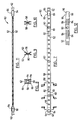
- Heat exchanger 10 includes two modules 12 and 14, each containing a separate flow circuit for accommodating a different fluid.
- module 12 could be used to cool automotive transmission oil or fluid
- module 14 could be used to cool automotive engine oil. It will be appreciated, however, that heat exchanger 10 could be used to heat different fluids as well.
- two modules 12, 14 are shown, any number of modules could be incorporated into a single heat exchanger 10.
- Heat exchanger 10 is formed of a plurality of stacked, hollow plate pairs 16, 18 although tubes could be used in place of the plate pairs.
- plate pairs are considered to be equivalent to tubes.
- Other flow conduits could be used as well, and collectively, all of these plate pairs, tubes or other conduits may sometimes be referred to as flow channels.
- Plate pairs 16 are formed of mating plates that have inwardly joined dimples 20 and are thus called dimpled plate pairs 16.
- Plate pairs 18 are formed of plates that have flat centre sections 22 and expanded metal turbulizers 24 are located inside the plate pairs. Plate pairs 18 are thus called flat plate pairs.
- Each of the plate pairs 16, 18 has mating end bosses 26, 28.
- end bosses have communicating openings 30, 32 to form an aligned flow manifold for the flow of fluid through the plate pairs.
- Some of the end bosses, such as end bosses 27 may not have openings therein, or these openings may be closed in other ways to provide a particular flow circuit inside the modules, as will be described further below.
- Heat exchanger 10 includes a top fin 34 located on top of the stacked plate pairs 16, and a bottom fin 36 located below the stacked plate pairs 18.
- Module 12 also has a bottom fin 36 and module 14 has a top fin 34.
- Intermediate fins 38 are located between the plate pairs. All of the fins 34, 36 and 38 extend between their respective end bosses 26, 27 and 28 located at the opposed ends of the plate pairs.
- Plate pairs 16, 18, or the tube equivalents, and fins 34, 36 and 38 are not considered to be part of the present invention, per se. Any type of plate or tube and any type of fins, either dimpled or of the flat turbulizer type, can be used in heat exchanger 10. It is part of the present invention, however, that the fins 34, 36 and 38 all be generally of the same height, and the end bosses 26, 27 and 28 all be generally of the same height. In other words, there is no need in heat exchanger 10 to use special fins or fins of different heights, or to use plate pairs or tubes where some of the plates or tubes have end bosses of different heights.
- Module 12 has a top mounting or end bracket 42, and module 14 has a bottom mounting or end bracket 44.
- Mounting brackets 42, 44 are shown separately in Figures 3 to 6.
- Module 12 also has a bottom mounting bracket 46 and module 14 has a top mounting bracket 48.
- All of the mounting brackets 42, 44, 46 and 48 are identical.
- Mounting brackets 46 and 48 are preferably formed into a subassembly 50 shown by itself in Figures 7 to 11 and described further below.
- brackets 42, 44, 46 and 48 are referred to as mounting brackets, they could also be called end brackets, because they need not be used for mounting either heat exchanger 10 or other components to heat exchanger 10.
- mounting brackets 42, 44, 46 and 48 are used interchangeably.
- mounting or end brackets 42, 44 have a planar central portion 52 and opposed offset end portions 54, 56 located in a plane parallel to and spaced from central portion 52.
- planar central portions 52 of top and bottom mounting brackets 42, 46 are in contact with respective top and bottom fins 34, 36.
- planar central portions 52 of top and bottom mounting brackets 48, 44 are in contact with respective top and bottom fins 34, 36 for this module.
- Offset end portions 54, 56 are in contact with an adjacent end boss 26 or 28 as the case may be. Offset end portions 54, 56 extend a first predetermined distance from planar central portion 52. This predetermined distance is equal to one-half the fin height of fins 34, 36 and 38.
- Planar central portions 52 also have spacing projections in the form of dimples 58, 60 extending transversely in a direction opposite to that of offset end portions 54, 56. Projections or dimples 58, 60 extend a second predetermined distance from planar central portion 52. That second predetermined distance is such that where two mounting or end brackets are located back-to-back as is the case with subassembly 50, the distance between the adjacent offset end portions at each end of the mounting brackets is equal to the height of end fittings 62 located therebetween. For the purposes of this disclosure, this fitting height is referred to as a third predetermined distance.
- one of the offset end portions 54 of mounting brackets 42, 44 is formed with a flow orifice 64, and the other offset end portion 56 is blank or closed.
- Offset end portions 56 are formed with peripheral notches 66 for error proofing the assembly of heat exchanger 10 and for indicating the fluid flow circuit inside the heat exchanger, as will be described further below. It will be appreciated also that peripheral notches 66 could be provided on offset end portions 54 instead of offset end portions 56 to accomplish the same results.
- end fittings 62 include internal flow passages 68 that communicate with flow orifices 64 in offset end portions 54.
- end fittings 62 have transverse openings which are aligned with flow orifices 64, and a staking operation is used to attach end fitting 62 to offset end portions 54 as indicated by the formed flanges 70 in Figure 2.
- heat exchanger 10 includes attaching or attachment brackets for mounting the heat exchanger in a desired location.
- Attachment brackets 72 can be any configuration desired, but they preferably have circular or semi-circular openings 74 for accommodating dimples 58 to help align attachment brackets 72 during the assembly of heat exchanger 10.
- Attachment brackets 72 are temporarily attached to mounting brackets 52, 54 by rivets 76, or by a type of swaging or staking operation referred to by the trademark TOGGLE LOCK, as will be described further below.
- suitable attachment brackets can also be located between mounting or end brackets 42, 44 in subassembly 50. This arrangement is particularly useful where it is desired to mount other components in front of or behind heat exchanger 10.
- dimples 60 are of larger diameter than dimples 58.
- the reason for this is to facilitate the attachment of central portions 52 to form subassembly 50.
- this is done using a punch and die set marketed in association with the trademark TOGGLE LOCK. It is a clinching operation where a punch pushes metals from both parts through to an expanding die that forms a button on the underside of the parts to hold them together. This is like a self-forming rivet, and as seen in Figure 9, the punch leaves a depression 78 on one side of the joined parts and a button 80 on the other side of the parts.
- the larger dimples 60 provide a little extra material for this operation to prevent the punch from breaking through the material.
- rivets or spot welding could be used to join the mounting brackets instead of the TOGGLE LOCK fastening device, if desired.
- Mounting or end brackets 42, 44, 46 and 48 are also formed with alignment holes 82 and peripheral notches 83 to help align the components during the assembly or subassembly process.
- the spacing projections can be in the form of elongate ribs 84.
- ribs 84 are rib segments to permit air to flow between the planar central portions 52 of subassembly 50, but the ribs could be full length, if desired. Also, the ribs could be transversely obliquely orientated rather than longitudinally orientated.
- the desired flow circuits or passes are first determined. For example, in module 12 in the heat exchanger shown in Figure 1, it is desired that fluid enter one of the end fittings 62, pass through an inlet flow orifice 64 in one of the offset end portions and into one of the end boss openings 30. The fluid then flows the length of one of the plate pairs 16. The flow is reversed at the opposite end of the plate pairs and comes back to exit through outlet orifices communicating with the other end fittings 62. Either end fitting 62 can be used as a flow inlet fitting; the other end fitting 62 being the flow outlet fitting. In module 14 the end fittings 62 are located to the right (not shown). Fluid flow passes through one end fitting 62 in a similar manner to travel along one or more of the plate pairs 18. The flow is then reversed, because the end bosses 28 form a manifold, and the fluid flows back to exit through the other end fitting 62.
- the desired number of plate pairs 18 and fins 34, 36 and 38 are stacked on top of bottom mounting bracket 44, after having staked an end fitting 62 to the offset end portion 54 of mounting bracket 44.
- a subassembly 50 is then mounted on top of the top fin 34.
- a desired number of plate pairs 16 are then stacked on top of subassembly 50, and top mounting bracket 52 is located on top of top fin 34 of module 12, again after having staked an end fitting 62 to the offset end portion 54 of top mounting bracket 42.
- the assembly is then permanently joined by brazing or soldering to complete the heat exchanger.
- subassembly 50 is shown in Figures 7 to 11 having a flow orifice offset end portion 54 located adjacent to a closed offset end portion 56, one of the mounting brackets can be turned end for end.
- the adjacent flow orifice offset end portions 54 could have an end fitting 62 with a transverse hole that passes right through the fitting to communicate with both orifices 64 allowing flow to go into or out of two adjacent modules simultaneously.
- a heat exchanger 10 can be made having any number of additional modules. Further, end fittings 62 can be orientated in other directions, such as transverse to the plate pairs.
Landscapes
- Engineering & Computer Science (AREA)
- Physics & Mathematics (AREA)
- Thermal Sciences (AREA)
- Mechanical Engineering (AREA)
- General Engineering & Computer Science (AREA)
- Heat-Exchange Devices With Radiators And Conduit Assemblies (AREA)
- Details Of Heat-Exchange And Heat-Transfer (AREA)
Applications Claiming Priority (3)
| Application Number | Priority Date | Filing Date | Title |
|---|---|---|---|
| CA002215173A CA2215173C (en) | 1997-09-11 | 1997-09-11 | Stepped dimpled mounting brackets for heat exchangers |
| CA2215173 | 1997-09-11 | ||
| PCT/CA1998/000868 WO1999013284A1 (en) | 1997-09-11 | 1998-09-10 | Stepped dimpled mounting brackets for heat exchangers |
Publications (2)
| Publication Number | Publication Date |
|---|---|
| EP1012523A1 EP1012523A1 (en) | 2000-06-28 |
| EP1012523B1 true EP1012523B1 (en) | 2003-05-02 |
Family
ID=4161439
Family Applications (1)
| Application Number | Title | Priority Date | Filing Date |
|---|---|---|---|
| EP98942438A Expired - Lifetime EP1012523B1 (en) | 1997-09-11 | 1998-09-10 | Stepped dimpled mounting brackets for heat exchangers |
Country Status (12)
| Country | Link |
|---|---|
| US (1) | US5964282A (sv) |
| EP (1) | EP1012523B1 (sv) |
| JP (1) | JP2001516007A (sv) |
| KR (1) | KR100394139B1 (sv) |
| AU (1) | AU737251B2 (sv) |
| BR (1) | BR9812080A (sv) |
| CA (1) | CA2215173C (sv) |
| DE (2) | DE19882664B4 (sv) |
| ES (1) | ES2202887T3 (sv) |
| GB (1) | GB2347997B (sv) |
| SE (1) | SE518770C2 (sv) |
| WO (1) | WO1999013284A1 (sv) |
Families Citing this family (32)
| Publication number | Priority date | Publication date | Assignee | Title |
|---|---|---|---|---|
| FR2803375B1 (fr) * | 1999-12-30 | 2002-03-22 | Valeo Thermique Moteur Sa | Echangeur de chaleur brase, notamment pour vehicules automobiles |
| US7854256B2 (en) * | 2001-07-26 | 2010-12-21 | Dana Canada Corporation | Plug bypass valves and heat exchangers |
| US20030019620A1 (en) * | 2001-07-30 | 2003-01-30 | Pineo Gregory Merle | Plug bypass valves and heat exchangers |
| US9557749B2 (en) | 2001-07-30 | 2017-01-31 | Dana Canada Corporation | Valves for bypass circuits in heat exchangers |
| US8960269B2 (en) | 2001-07-30 | 2015-02-24 | Dana Canada Corporation | Plug bypass valve and heat exchanger |
| CA2366227C (en) * | 2001-12-27 | 2007-12-04 | John W. Izard | Mounting bracket for heat exchanger cores |
| GB2384299B (en) * | 2002-01-22 | 2006-03-22 | Llanelli Radiators Ltd | Automotive heat exchanger |
| CA2372399C (en) * | 2002-02-19 | 2010-10-26 | Long Manufacturing Ltd. | Low profile finned heat exchanger |
| CA2389119A1 (en) * | 2002-06-04 | 2003-12-04 | Christopher R. Shore | Lateral plate finned heat exchanger |
| KR100864843B1 (ko) * | 2002-08-08 | 2008-10-23 | 한라공조주식회사 | 열교환기용 냉각튜브 및 이를 이용한 열교환기 |
| CA2423193A1 (en) * | 2003-03-24 | 2004-09-24 | Dana Canada Corporation | Lateral plate surface cooled heat exchanger |
| CA2433975C (en) * | 2003-06-27 | 2012-01-17 | Dana Canada Corporation | Ribbed mounting bracket for heat exchangers |
| CA2433697A1 (en) * | 2003-06-27 | 2004-12-27 | Dana Canada Corporation | Vibration-resistant mounting bracket for heat exchangers |
| CA2454283A1 (en) * | 2003-12-29 | 2005-06-29 | Anis Muhammad | Insert molded structure and method for the manufacture thereof |
| US7051789B2 (en) * | 2004-04-22 | 2006-05-30 | Dana Canada Corporation | Two-piece mounting bracket for heat exchanger |
| US7013962B2 (en) * | 2004-07-23 | 2006-03-21 | Homayoun Sanatgar | High pressure fluid cooler |
| DE102004044872A1 (de) * | 2004-09-14 | 2006-03-16 | Behr Gmbh & Co. Kg | Befestigungsanordnung für einen Ladeluftkühler, insbesondere ein Kühlmodul |
| US7540431B2 (en) * | 2004-11-24 | 2009-06-02 | Dana Canada Corporation | By-pass valve for heat exchanger |
| CA2607994C (en) * | 2005-05-24 | 2016-01-19 | Dana Canada Corporation | Multifluid heat exchanger |
| US7264045B2 (en) * | 2005-08-23 | 2007-09-04 | Delphi Technologies, Inc. | Plate-type evaporator to suppress noise and maintain thermal performance |
| DE102005058769B4 (de) * | 2005-12-09 | 2016-11-03 | Modine Manufacturing Co. | Ladeluftkühler |
| DE102006033771A1 (de) | 2006-07-21 | 2008-01-24 | Modine Manufacturing Co., Racine | Wärmetauscher |
| US7703505B2 (en) * | 2006-11-24 | 2010-04-27 | Dana Canada Corporation | Multifluid two-dimensional heat exchanger |
| US8288118B2 (en) * | 2007-09-19 | 2012-10-16 | Becton, Dickinson And Company | Method of analyzing various surface chemistries for culturing a given cell line |
| JP5009413B2 (ja) * | 2010-12-22 | 2012-08-22 | シャープ株式会社 | 熱交換器及びそれを搭載した空気調和機 |
| US8485504B2 (en) * | 2011-03-09 | 2013-07-16 | Koch-Glitsch, Lp | Apparatus for supporting internals within a mass transfer column and process involving same |
| KR20150020615A (ko) | 2012-05-31 | 2015-02-26 | 다나 캐나다 코포레이션 | 통합 밸브를 가진 열교환기 조립체 |
| CA2839884C (en) * | 2013-02-19 | 2020-10-27 | Scambia Holdings Cyprus Limited | Plate heat exchanger including separating elements |
| GB2527494B (en) * | 2014-05-16 | 2019-09-04 | Denso Marston Ltd | A heat exchanger assembly |
| EP3414509A4 (en) * | 2016-02-09 | 2019-09-18 | Modine Manufacturing Company | HEAT EXCHANGER AND CORE FOR A HEAT EXCHANGER |
| US10900557B2 (en) | 2018-11-13 | 2021-01-26 | Dana Canada Corporation | Heat exchanger assembly with integrated valve with pressure relief feature for hot and cold fluids |
| KR20200124577A (ko) * | 2019-04-24 | 2020-11-03 | 현대자동차주식회사 | 전력변환 장치용 냉각 시스템 |
Family Cites Families (20)
| Publication number | Priority date | Publication date | Assignee | Title |
|---|---|---|---|---|
| FR2077678A1 (en) * | 1970-02-04 | 1971-11-05 | Chausson Usines Sa | Heat exchange elements - of variable length |
| US4002201A (en) * | 1974-05-24 | 1977-01-11 | Borg-Warner Corporation | Multiple fluid stacked plate heat exchanger |
| US4274482A (en) * | 1978-08-21 | 1981-06-23 | Nihon Radiator Co., Ltd. | Laminated evaporator |
| US4258785A (en) * | 1980-02-08 | 1981-03-31 | Borg-Warner Corporation | Heat exchanger interplate fitting |
| US4561494A (en) * | 1983-04-29 | 1985-12-31 | Modine Manufacturing Company | Heat exchanger with back to back turbulators and flow directing embossments |
| US4854380A (en) * | 1985-10-25 | 1989-08-08 | Mitsubishi Denki Kabushiki Kaisha | Heat exchanger |
| US4815532A (en) * | 1986-02-28 | 1989-03-28 | Showa Aluminum Kabushiki Kaisha | Stack type heat exchanger |
| CA1313183C (en) * | 1989-02-24 | 1993-01-26 | Allan K. So | Embossed plate heat exchanger |
| SE462763B (sv) * | 1989-04-28 | 1990-08-27 | Torell Ab | Plattvaermevaexlare/kylare samt saett att tillverka denna |
| US4932469A (en) * | 1989-10-04 | 1990-06-12 | Blackstone Corporation | Automotive condenser |
| CA2056678C (en) * | 1991-11-29 | 1995-10-31 | John G. Burgers | Full fin evaporator core |
| CA2075686C (en) * | 1992-04-03 | 2003-02-11 | Nobuyuki Okuda | Stack type evaporator |
| US5180004A (en) * | 1992-06-19 | 1993-01-19 | General Motors Corporation | Integral heater-evaporator core |
| US5325915A (en) * | 1993-07-14 | 1994-07-05 | Earl's Supply Co. | Modular cooler |
| US5632331A (en) * | 1993-09-30 | 1997-05-27 | Sanden Corporation | Heat exchanger |
| US5413169A (en) * | 1993-12-17 | 1995-05-09 | Ford Motor Company | Automotive evaporator manifold |
| KR100353020B1 (ko) * | 1993-12-28 | 2003-01-10 | 쇼와 덴코 가부시키가이샤 | 적층형열교환기 |
| FR2721099B1 (fr) * | 1994-06-08 | 1996-07-19 | Valeo Thermique Moteur Sa | Echangeur de chaleur utile notamment pour le refroidissement d'un flux d'air à haute température. |
| JP3028461B2 (ja) * | 1995-03-30 | 2000-04-04 | 株式会社ゼクセル | 積層型熱交換器 |
| JP3399210B2 (ja) * | 1996-02-13 | 2003-04-21 | 株式会社デンソー | 積層型熱交換器 |
-
1997
- 1997-09-11 CA CA002215173A patent/CA2215173C/en not_active Expired - Lifetime
-
1998
- 1998-06-26 US US09/105,978 patent/US5964282A/en not_active Expired - Lifetime
- 1998-09-10 ES ES98942438T patent/ES2202887T3/es not_active Expired - Lifetime
- 1998-09-10 BR BR9812080-8A patent/BR9812080A/pt not_active IP Right Cessation
- 1998-09-10 EP EP98942438A patent/EP1012523B1/en not_active Expired - Lifetime
- 1998-09-10 WO PCT/CA1998/000868 patent/WO1999013284A1/en active IP Right Grant
- 1998-09-10 GB GB0005887A patent/GB2347997B/en not_active Expired - Lifetime
- 1998-09-10 JP JP2000511027A patent/JP2001516007A/ja active Pending
- 1998-09-10 AU AU90592/98A patent/AU737251B2/en not_active Ceased
- 1998-09-10 DE DE19882664T patent/DE19882664B4/de not_active Expired - Lifetime
- 1998-09-10 KR KR10-2000-7002624A patent/KR100394139B1/ko not_active IP Right Cessation
- 1998-09-10 DE DE69814101T patent/DE69814101D1/de not_active Expired - Lifetime
-
2000
- 2000-03-07 SE SE0000739A patent/SE518770C2/sv not_active IP Right Cessation
Also Published As
| Publication number | Publication date |
|---|---|
| BR9812080A (pt) | 2000-09-26 |
| AU9059298A (en) | 1999-03-29 |
| DE19882664T1 (de) | 2000-11-16 |
| CA2215173C (en) | 2004-04-06 |
| JP2001516007A (ja) | 2001-09-25 |
| US5964282A (en) | 1999-10-12 |
| AU737251B2 (en) | 2001-08-16 |
| EP1012523A1 (en) | 2000-06-28 |
| SE0000739L (sv) | 2000-04-12 |
| GB2347997B (en) | 2002-05-08 |
| KR20010023927A (ko) | 2001-03-26 |
| GB2347997A (en) | 2000-09-20 |
| WO1999013284A1 (en) | 1999-03-18 |
| CA2215173A1 (en) | 1999-03-11 |
| ES2202887T3 (es) | 2004-04-01 |
| SE0000739D0 (sv) | 2000-03-07 |
| DE69814101D1 (de) | 2003-06-05 |
| GB0005887D0 (en) | 2000-05-03 |
| DE19882664B4 (de) | 2004-08-19 |
| KR100394139B1 (ko) | 2003-08-09 |
| SE518770C2 (sv) | 2002-11-19 |
Similar Documents
| Publication | Publication Date | Title |
|---|---|---|
| EP1012523B1 (en) | Stepped dimpled mounting brackets for heat exchangers | |
| CA2215172C (en) | Baffle insert for heat exchangers | |
| JP3713079B2 (ja) | 高効率、小体積の冷媒蒸発器 | |
| CA2081695C (en) | Evaporator or evaporator/condenser | |
| US4917180A (en) | Heat exchanger with laminated header and tank and method of manufacture | |
| US6920918B2 (en) | Heat exchanger | |
| US5450896A (en) | Two-piece header | |
| US6446713B1 (en) | Heat exchanger manifold | |
| EP0197652A1 (en) | A heat exchanger core construction utilizing a plate member adaptable for producing either a single or double pass flow arrangement | |
| US20050061489A1 (en) | Integrated multi-function return tube for combo heat exchangers | |
| US20090151918A1 (en) | Heat Exchanger for Automobile and Fabricating Method Thereof | |
| JPH0611291A (ja) | 冷却システム用の積層プレートヘッダー及びその製造方法 | |
| US5209292A (en) | Condenser header and tank assembly with interference fit baffle | |
| KR20030080004A (ko) | 열교환기 | |
| US20020179291A1 (en) | Evaporator and method of making same | |
| US5513700A (en) | Automotive evaporator manifold | |
| US4903389A (en) | Heat exchanger with laminated header and method of manufacture | |
| KR200159030Y1 (ko) | 자동차용 증발기 | |
| EP1610080A2 (en) | Stacking-type, multi-flow, heat exchangers and methods for manufacturing such heat exhangers | |
| JP2586753Y2 (ja) | 熱交換器 | |
| KR100361038B1 (ko) | 열교환기의 배플인서트 및 그에 의한 유로변경방법 | |
| JP2000283603A (ja) | 熱交換器 | |
| JPH07103683A (ja) | 熱交換器 | |
| JP2603148Y2 (ja) | 熱交換器 | |
| JPH1047887A (ja) | 熱交換器 |
Legal Events
| Date | Code | Title | Description |
|---|---|---|---|
| PUAI | Public reference made under article 153(3) epc to a published international application that has entered the european phase |
Free format text: ORIGINAL CODE: 0009012 |
|
| 17P | Request for examination filed |
Effective date: 20000404 |
|
| AK | Designated contracting states |
Kind code of ref document: A1 Designated state(s): DE ES FR GB IT SE |
|
| 17Q | First examination report despatched |
Effective date: 20001031 |
|
| GRAH | Despatch of communication of intention to grant a patent |
Free format text: ORIGINAL CODE: EPIDOS IGRA |
|
| GRAH | Despatch of communication of intention to grant a patent |
Free format text: ORIGINAL CODE: EPIDOS IGRA |
|
| GRAA | (expected) grant |
Free format text: ORIGINAL CODE: 0009210 |
|
| AK | Designated contracting states |
Designated state(s): DE ES FR GB IT SE |
|
| REG | Reference to a national code |
Ref country code: GB Ref legal event code: FG4D |
|
| REF | Corresponds to: |
Ref document number: 69814101 Country of ref document: DE Date of ref document: 20030605 Kind code of ref document: P |
|
| PG25 | Lapsed in a contracting state [announced via postgrant information from national office to epo] |
Ref country code: SE Free format text: LAPSE BECAUSE OF FAILURE TO SUBMIT A TRANSLATION OF THE DESCRIPTION OR TO PAY THE FEE WITHIN THE PRESCRIBED TIME-LIMIT Effective date: 20030802 |
|
| PG25 | Lapsed in a contracting state [announced via postgrant information from national office to epo] |
Ref country code: DE Free format text: LAPSE BECAUSE OF FAILURE TO SUBMIT A TRANSLATION OF THE DESCRIPTION OR TO PAY THE FEE WITHIN THE PRESCRIBED TIME-LIMIT Effective date: 20030805 |
|
| PGFP | Annual fee paid to national office [announced via postgrant information from national office to epo] |
Ref country code: GB Payment date: 20030902 Year of fee payment: 6 |
|
| REG | Reference to a national code |
Ref country code: ES Ref legal event code: PC2A |
|
| REG | Reference to a national code |
Ref country code: FR Ref legal event code: TP |
|
| PLBE | No opposition filed within time limit |
Free format text: ORIGINAL CODE: 0009261 |
|
| STAA | Information on the status of an ep patent application or granted ep patent |
Free format text: STATUS: NO OPPOSITION FILED WITHIN TIME LIMIT |
|
| ET | Fr: translation filed | ||
| REG | Reference to a national code |
Ref country code: ES Ref legal event code: FG2A Ref document number: 2202887 Country of ref document: ES Kind code of ref document: T3 |
|
| 26N | No opposition filed |
Effective date: 20040203 |
|
| PG25 | Lapsed in a contracting state [announced via postgrant information from national office to epo] |
Ref country code: GB Free format text: LAPSE BECAUSE OF NON-PAYMENT OF DUE FEES Effective date: 20040910 |
|
| GBPC | Gb: european patent ceased through non-payment of renewal fee |
Effective date: 20040910 |
|
| PGFP | Annual fee paid to national office [announced via postgrant information from national office to epo] |
Ref country code: FR Payment date: 20060918 Year of fee payment: 9 |
|
| PGFP | Annual fee paid to national office [announced via postgrant information from national office to epo] |
Ref country code: ES Payment date: 20060926 Year of fee payment: 9 |
|
| REG | Reference to a national code |
Ref country code: FR Ref legal event code: ST Effective date: 20080531 |
|
| PG25 | Lapsed in a contracting state [announced via postgrant information from national office to epo] |
Ref country code: FR Free format text: LAPSE BECAUSE OF NON-PAYMENT OF DUE FEES Effective date: 20071001 |
|
| REG | Reference to a national code |
Ref country code: ES Ref legal event code: FD2A Effective date: 20070911 |
|
| PG25 | Lapsed in a contracting state [announced via postgrant information from national office to epo] |
Ref country code: ES Free format text: LAPSE BECAUSE OF NON-PAYMENT OF DUE FEES Effective date: 20070911 |
|
| PGFP | Annual fee paid to national office [announced via postgrant information from national office to epo] |
Ref country code: IT Payment date: 20090928 Year of fee payment: 12 |
|
| PG25 | Lapsed in a contracting state [announced via postgrant information from national office to epo] |
Ref country code: IT Free format text: LAPSE BECAUSE OF NON-PAYMENT OF DUE FEES Effective date: 20100910 |