EP1010896A2 - Druckregler für Lastmeldedruck - Google Patents
Druckregler für Lastmeldedruck Download PDFInfo
- Publication number
- EP1010896A2 EP1010896A2 EP99310015A EP99310015A EP1010896A2 EP 1010896 A2 EP1010896 A2 EP 1010896A2 EP 99310015 A EP99310015 A EP 99310015A EP 99310015 A EP99310015 A EP 99310015A EP 1010896 A2 EP1010896 A2 EP 1010896A2
- Authority
- EP
- European Patent Office
- Prior art keywords
- passage
- load sense
- return
- piston
- valve
- Prior art date
- Legal status (The legal status is an assumption and is not a legal conclusion. Google has not performed a legal analysis and makes no representation as to the accuracy of the status listed.)
- Withdrawn
Links
- 239000012530 fluid Substances 0.000 claims abstract description 35
- 238000006243 chemical reaction Methods 0.000 claims description 8
- 230000008878 coupling Effects 0.000 claims 1
- 238000010168 coupling process Methods 0.000 claims 1
- 238000005859 coupling reaction Methods 0.000 claims 1
- 230000003071 parasitic effect Effects 0.000 description 5
- 230000007935 neutral effect Effects 0.000 description 2
- 238000011109 contamination Methods 0.000 description 1
- 238000006073 displacement reaction Methods 0.000 description 1
- 230000004048 modification Effects 0.000 description 1
- 238000012986 modification Methods 0.000 description 1
Images


Classifications
-
- E—FIXED CONSTRUCTIONS
- E02—HYDRAULIC ENGINEERING; FOUNDATIONS; SOIL SHIFTING
- E02F—DREDGING; SOIL-SHIFTING
- E02F9/00—Component parts of dredgers or soil-shifting machines, not restricted to one of the kinds covered by groups E02F3/00 - E02F7/00
- E02F9/20—Drives; Control devices
- E02F9/22—Hydraulic or pneumatic drives
- E02F9/2264—Arrangements or adaptations of elements for hydraulic drives
- E02F9/2267—Valves or distributors
-
- E—FIXED CONSTRUCTIONS
- E02—HYDRAULIC ENGINEERING; FOUNDATIONS; SOIL SHIFTING
- E02F—DREDGING; SOIL-SHIFTING
- E02F9/00—Component parts of dredgers or soil-shifting machines, not restricted to one of the kinds covered by groups E02F3/00 - E02F7/00
- E02F9/20—Drives; Control devices
- E02F9/22—Hydraulic or pneumatic drives
- E02F9/2221—Control of flow rate; Load sensing arrangements
- E02F9/2225—Control of flow rate; Load sensing arrangements using pressure-compensating valves
-
- E—FIXED CONSTRUCTIONS
- E02—HYDRAULIC ENGINEERING; FOUNDATIONS; SOIL SHIFTING
- E02F—DREDGING; SOIL-SHIFTING
- E02F9/00—Component parts of dredgers or soil-shifting machines, not restricted to one of the kinds covered by groups E02F3/00 - E02F7/00
- E02F9/20—Drives; Control devices
- E02F9/22—Hydraulic or pneumatic drives
- E02F9/2264—Arrangements or adaptations of elements for hydraulic drives
- E02F9/2271—Actuators and supports therefor and protection therefor
-
- E—FIXED CONSTRUCTIONS
- E02—HYDRAULIC ENGINEERING; FOUNDATIONS; SOIL SHIFTING
- E02F—DREDGING; SOIL-SHIFTING
- E02F9/00—Component parts of dredgers or soil-shifting machines, not restricted to one of the kinds covered by groups E02F3/00 - E02F7/00
- E02F9/20—Drives; Control devices
- E02F9/22—Hydraulic or pneumatic drives
- E02F9/2278—Hydraulic circuits
- E02F9/2296—Systems with a variable displacement pump
-
- F—MECHANICAL ENGINEERING; LIGHTING; HEATING; WEAPONS; BLASTING
- F15—FLUID-PRESSURE ACTUATORS; HYDRAULICS OR PNEUMATICS IN GENERAL
- F15B—SYSTEMS ACTING BY MEANS OF FLUIDS IN GENERAL; FLUID-PRESSURE ACTUATORS, e.g. SERVOMOTORS; DETAILS OF FLUID-PRESSURE SYSTEMS, NOT OTHERWISE PROVIDED FOR
- F15B11/00—Servomotor systems without provision for follow-up action; Circuits therefor
- F15B11/16—Servomotor systems without provision for follow-up action; Circuits therefor with two or more servomotors
- F15B11/161—Servomotor systems without provision for follow-up action; Circuits therefor with two or more servomotors with sensing of servomotor demand or load
- F15B11/165—Servomotor systems without provision for follow-up action; Circuits therefor with two or more servomotors with sensing of servomotor demand or load for adjusting the pump output or bypass in response to demand
-
- F—MECHANICAL ENGINEERING; LIGHTING; HEATING; WEAPONS; BLASTING
- F04—POSITIVE - DISPLACEMENT MACHINES FOR LIQUIDS; PUMPS FOR LIQUIDS OR ELASTIC FLUIDS
- F04B—POSITIVE-DISPLACEMENT MACHINES FOR LIQUIDS; PUMPS
- F04B2205/00—Fluid parameters
- F04B2205/09—Flow through the pump
-
- F—MECHANICAL ENGINEERING; LIGHTING; HEATING; WEAPONS; BLASTING
- F15—FLUID-PRESSURE ACTUATORS; HYDRAULICS OR PNEUMATICS IN GENERAL
- F15B—SYSTEMS ACTING BY MEANS OF FLUIDS IN GENERAL; FLUID-PRESSURE ACTUATORS, e.g. SERVOMOTORS; DETAILS OF FLUID-PRESSURE SYSTEMS, NOT OTHERWISE PROVIDED FOR
- F15B2211/00—Circuits for servomotor systems
- F15B2211/20—Fluid pressure source, e.g. accumulator or variable axial piston pump
- F15B2211/205—Systems with pumps
- F15B2211/2053—Type of pump
- F15B2211/20546—Type of pump variable capacity
- F15B2211/20553—Type of pump variable capacity with pilot circuit, e.g. for controlling a swash plate
-
- F—MECHANICAL ENGINEERING; LIGHTING; HEATING; WEAPONS; BLASTING
- F15—FLUID-PRESSURE ACTUATORS; HYDRAULICS OR PNEUMATICS IN GENERAL
- F15B—SYSTEMS ACTING BY MEANS OF FLUIDS IN GENERAL; FLUID-PRESSURE ACTUATORS, e.g. SERVOMOTORS; DETAILS OF FLUID-PRESSURE SYSTEMS, NOT OTHERWISE PROVIDED FOR
- F15B2211/00—Circuits for servomotor systems
- F15B2211/20—Fluid pressure source, e.g. accumulator or variable axial piston pump
- F15B2211/25—Pressure control functions
- F15B2211/253—Pressure margin control, e.g. pump pressure in relation to load pressure
-
- F—MECHANICAL ENGINEERING; LIGHTING; HEATING; WEAPONS; BLASTING
- F15—FLUID-PRESSURE ACTUATORS; HYDRAULICS OR PNEUMATICS IN GENERAL
- F15B—SYSTEMS ACTING BY MEANS OF FLUIDS IN GENERAL; FLUID-PRESSURE ACTUATORS, e.g. SERVOMOTORS; DETAILS OF FLUID-PRESSURE SYSTEMS, NOT OTHERWISE PROVIDED FOR
- F15B2211/00—Circuits for servomotor systems
- F15B2211/30—Directional control
- F15B2211/305—Directional control characterised by the type of valves
- F15B2211/30505—Non-return valves, i.e. check valves
-
- F—MECHANICAL ENGINEERING; LIGHTING; HEATING; WEAPONS; BLASTING
- F15—FLUID-PRESSURE ACTUATORS; HYDRAULICS OR PNEUMATICS IN GENERAL
- F15B—SYSTEMS ACTING BY MEANS OF FLUIDS IN GENERAL; FLUID-PRESSURE ACTUATORS, e.g. SERVOMOTORS; DETAILS OF FLUID-PRESSURE SYSTEMS, NOT OTHERWISE PROVIDED FOR
- F15B2211/00—Circuits for servomotor systems
- F15B2211/30—Directional control
- F15B2211/305—Directional control characterised by the type of valves
- F15B2211/30525—Directional control valves, e.g. 4/3-directional control valve
- F15B2211/3053—In combination with a pressure compensating valve
- F15B2211/30555—Inlet and outlet of the pressure compensating valve being connected to the directional control valve
-
- F—MECHANICAL ENGINEERING; LIGHTING; HEATING; WEAPONS; BLASTING
- F15—FLUID-PRESSURE ACTUATORS; HYDRAULICS OR PNEUMATICS IN GENERAL
- F15B—SYSTEMS ACTING BY MEANS OF FLUIDS IN GENERAL; FLUID-PRESSURE ACTUATORS, e.g. SERVOMOTORS; DETAILS OF FLUID-PRESSURE SYSTEMS, NOT OTHERWISE PROVIDED FOR
- F15B2211/00—Circuits for servomotor systems
- F15B2211/30—Directional control
- F15B2211/31—Directional control characterised by the positions of the valve element
- F15B2211/3122—Special positions other than the pump port being connected to working ports or the working ports being connected to the return line
- F15B2211/3127—Floating position connecting the working ports and the return line
-
- F—MECHANICAL ENGINEERING; LIGHTING; HEATING; WEAPONS; BLASTING
- F15—FLUID-PRESSURE ACTUATORS; HYDRAULICS OR PNEUMATICS IN GENERAL
- F15B—SYSTEMS ACTING BY MEANS OF FLUIDS IN GENERAL; FLUID-PRESSURE ACTUATORS, e.g. SERVOMOTORS; DETAILS OF FLUID-PRESSURE SYSTEMS, NOT OTHERWISE PROVIDED FOR
- F15B2211/00—Circuits for servomotor systems
- F15B2211/30—Directional control
- F15B2211/31—Directional control characterised by the positions of the valve element
- F15B2211/3144—Directional control characterised by the positions of the valve element the positions being continuously variable, e.g. as realised by proportional valves
-
- F—MECHANICAL ENGINEERING; LIGHTING; HEATING; WEAPONS; BLASTING
- F15—FLUID-PRESSURE ACTUATORS; HYDRAULICS OR PNEUMATICS IN GENERAL
- F15B—SYSTEMS ACTING BY MEANS OF FLUIDS IN GENERAL; FLUID-PRESSURE ACTUATORS, e.g. SERVOMOTORS; DETAILS OF FLUID-PRESSURE SYSTEMS, NOT OTHERWISE PROVIDED FOR
- F15B2211/00—Circuits for servomotor systems
- F15B2211/30—Directional control
- F15B2211/315—Directional control characterised by the connections of the valve or valves in the circuit
- F15B2211/3157—Directional control characterised by the connections of the valve or valves in the circuit being connected to a pressure source, an output member and a return line
- F15B2211/31576—Directional control characterised by the connections of the valve or valves in the circuit being connected to a pressure source, an output member and a return line having a single pressure source and a single output member
-
- F—MECHANICAL ENGINEERING; LIGHTING; HEATING; WEAPONS; BLASTING
- F15—FLUID-PRESSURE ACTUATORS; HYDRAULICS OR PNEUMATICS IN GENERAL
- F15B—SYSTEMS ACTING BY MEANS OF FLUIDS IN GENERAL; FLUID-PRESSURE ACTUATORS, e.g. SERVOMOTORS; DETAILS OF FLUID-PRESSURE SYSTEMS, NOT OTHERWISE PROVIDED FOR
- F15B2211/00—Circuits for servomotor systems
- F15B2211/30—Directional control
- F15B2211/32—Directional control characterised by the type of actuation
- F15B2211/321—Directional control characterised by the type of actuation mechanically
- F15B2211/324—Directional control characterised by the type of actuation mechanically manually, e.g. by using a lever or pedal
-
- F—MECHANICAL ENGINEERING; LIGHTING; HEATING; WEAPONS; BLASTING
- F15—FLUID-PRESSURE ACTUATORS; HYDRAULICS OR PNEUMATICS IN GENERAL
- F15B—SYSTEMS ACTING BY MEANS OF FLUIDS IN GENERAL; FLUID-PRESSURE ACTUATORS, e.g. SERVOMOTORS; DETAILS OF FLUID-PRESSURE SYSTEMS, NOT OTHERWISE PROVIDED FOR
- F15B2211/00—Circuits for servomotor systems
- F15B2211/60—Circuit components or control therefor
- F15B2211/605—Load sensing circuits
- F15B2211/6051—Load sensing circuits having valve means between output member and the load sensing circuit
- F15B2211/6055—Load sensing circuits having valve means between output member and the load sensing circuit using pressure relief valves
-
- F—MECHANICAL ENGINEERING; LIGHTING; HEATING; WEAPONS; BLASTING
- F15—FLUID-PRESSURE ACTUATORS; HYDRAULICS OR PNEUMATICS IN GENERAL
- F15B—SYSTEMS ACTING BY MEANS OF FLUIDS IN GENERAL; FLUID-PRESSURE ACTUATORS, e.g. SERVOMOTORS; DETAILS OF FLUID-PRESSURE SYSTEMS, NOT OTHERWISE PROVIDED FOR
- F15B2211/00—Circuits for servomotor systems
- F15B2211/60—Circuit components or control therefor
- F15B2211/65—Methods of control of the load sensing pressure
- F15B2211/653—Methods of control of the load sensing pressure the load sensing pressure being higher than the load pressure
-
- F—MECHANICAL ENGINEERING; LIGHTING; HEATING; WEAPONS; BLASTING
- F15—FLUID-PRESSURE ACTUATORS; HYDRAULICS OR PNEUMATICS IN GENERAL
- F15B—SYSTEMS ACTING BY MEANS OF FLUIDS IN GENERAL; FLUID-PRESSURE ACTUATORS, e.g. SERVOMOTORS; DETAILS OF FLUID-PRESSURE SYSTEMS, NOT OTHERWISE PROVIDED FOR
- F15B2211/00—Circuits for servomotor systems
- F15B2211/70—Output members, e.g. hydraulic motors or cylinders or control therefor
- F15B2211/705—Output members, e.g. hydraulic motors or cylinders or control therefor characterised by the type of output members or actuators
- F15B2211/7051—Linear output members
- F15B2211/7053—Double-acting output members
- F15B2211/7054—Having equal piston areas
-
- Y—GENERAL TAGGING OF NEW TECHNOLOGICAL DEVELOPMENTS; GENERAL TAGGING OF CROSS-SECTIONAL TECHNOLOGIES SPANNING OVER SEVERAL SECTIONS OF THE IPC; TECHNICAL SUBJECTS COVERED BY FORMER USPC CROSS-REFERENCE ART COLLECTIONS [XRACs] AND DIGESTS
- Y10—TECHNICAL SUBJECTS COVERED BY FORMER USPC
- Y10T—TECHNICAL SUBJECTS COVERED BY FORMER US CLASSIFICATION
- Y10T137/00—Fluid handling
- Y10T137/2496—Self-proportioning or correlating systems
- Y10T137/2559—Self-controlled branched flow systems
- Y10T137/2574—Bypass or relief controlled by main line fluid condition
- Y10T137/2579—Flow rate responsive
- Y10T137/2587—Bypass or relief valve biased open
-
- Y—GENERAL TAGGING OF NEW TECHNOLOGICAL DEVELOPMENTS; GENERAL TAGGING OF CROSS-SECTIONAL TECHNOLOGIES SPANNING OVER SEVERAL SECTIONS OF THE IPC; TECHNICAL SUBJECTS COVERED BY FORMER USPC CROSS-REFERENCE ART COLLECTIONS [XRACs] AND DIGESTS
- Y10—TECHNICAL SUBJECTS COVERED BY FORMER USPC
- Y10T—TECHNICAL SUBJECTS COVERED BY FORMER US CLASSIFICATION
- Y10T137/00—Fluid handling
- Y10T137/8593—Systems
- Y10T137/87169—Supply and exhaust
- Y10T137/87177—With bypass
- Y10T137/87185—Controlled by supply or exhaust valve
Definitions
- the present invention relates to a load sense pressure controller, and more particularly, the present invention relates to load sense pressure controller, bleed-off systems.
- Hydraulic cylinders and motors In order to perform their various functions.
- the hydraulic cylinders or motors are powered by a hydraulic pump, such as a swash plate pump, which is connected through a fluid control valve generally operated directly or indirectly by manually manipulated handles, cables or the like which control flow of hydraulic fluid to the hydraulic cylinders or motors.
- the directional control valves generally include a body having a pressure port which is connected to the pump; tank ports which are connected to a tank or reservoir for hydraulic fluid, and work ports connected to one or more hydraulic cylinders.
- the operating devices selectively connect various ports with one another in order to control operation of hydraulic cylinders so that fluid is delivered to the cylinders and exhausted from the cylinders in accordance with the operator's purposes.
- Fluid control valves under consideration with respect to this invention include a body having a bore formed therein which receives a spool with a plurality of circumferential grooves thereon. The various ports are in communication with the bore via passageways which are selectively connected by positioning the spool axially with the bore.
- directional control valves are classified as open center systems, closed center systems, and load sensing systems.
- Open center systems are relatively inexpensive, uncomplicated, and imprecise, whereas closed center systems are responsive and precisely controllable but relatively expensive. Both open and closed center systems tend to be inefficient.
- Load sensing systems which are the subject of this invention, tend to be relatively efficient because the pump which generates the flow of fluid to the fluid control valve delivers that fluid at a variable flow rate and at a variable output pressure based upon the instantaneous requirements of the device controlled by hydraulic cylinders connected to the directional control valve.
- the load sensing or pressure compensating valve may be either a pre-pressure compensated valve or a post-pressure compensation valve.
- the compensator is positioned between the spool and the output work port of the fluid control valve to regulate the pressure of the fluid supplied from the spool to a predetermined magnitude less than the pressure of the fluid at the inlet pressure port but greater than the pressure of the fluid in the active work port. Accordingly, a constant pressure differential is maintained across the spool, resulting in a constant flow of fluid therethrough, regardless of changing load requirements.
- a number of post-pressure compensator structures are known in the art; however, these known arrangements are rather complicated and/or require a number of components, and therefore are relatively expensive or difficult to service.
- employment of post-pressure compensators can be further improved by having the components function so that maximum system operating pressure is adjusted, whereby maximum pump output flow is achieved at maximum system operating pressure.
- the present invention is directed to a flow limiter useful in a controlled flow of hydraulic fluid from a pump
- the directional control valve includes a valve body with a load sense port, an inlet port, a return connected to tank and a load sense passage.
- the flow limiter is in communication with the load sense passage and the return.
- the valve normally connects the load sense passage to a compensator for the pump and includes a pressure controlling orifice communicating with the return.
- a pressure responsive bias urges the valve to connect the load sense passage to return passage of the valve with a selected force, the valve having a reaction surface for overcoming the bias when the pressure in the load sense passage of the valve exceeds the selected force of the bias.
- communication between the load sense passage and tank passage causes at least a substantial portion of the fluid from the load sense passage of the valve to be throttled through the pressure controlling orifice to the return.
- the element is a piston slidable within the barrel, the reaction surface being on the piston and the bias being a spring urging the piston to the first position.
- the piston has an axially extended stepped bore and a radial bore, wherein the axially stepped bore includes the pressure controlling orifice and is in communication with the return while the radial bore is in communication with the load sense passage.
- the flow limiter is configured as a cartridge.
- the aforedescribed flow limiter is in combination with a control valve adapted to control the flow of hydraulic fluid from a pump, wherein the directional control valve includes a valve body with a load sense port, an inlet port, a return port, a load sense passage, and a tank passage.
- the present invention is directed to a flow limiter cartridge wherein the cartridge includes a body in the form of a barrel having threaded bores at both ends and at least one lateral opening intermediate the ends.
- the first plug is threaded into the first end, the first plug being adapted for connection to a load sense line of a pump.
- a second plug is disposed at the second end and is adapted for communication with a tank passage of a control valve.
- a piston is disposed between the plugs and is urged against the first plug, the piston having a passage normally aligned with the lateral opening in the body, which lateral opening is adapted to communicate with a load sense passage of a control valve.
- a pressure controlling orifice is disposed in the piston and communicates through the second plug which is adapted in turn to connect to a tank passage of a control valve when the load sense pressure exceeds a predetermined pressure.
- the present invention also relates to the combination of the aforedescribed flow limiter and a directional control valve adapted to control flow of hydraulic fluid from a pump wherein the directional control valve includes a valve body with a load sense port, an inlet port, a return port, a load sense passage and a tank passage connected to return hydraulic fluid to tank.
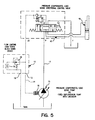
- FIGS. 1-3 there is shown a directional control valve 10 having a cover assembly 11 with a bleed-down cartridge 12, configured in accordance with the present invention, which control valve has a port 13 which is connected via a load sense line 14 to a pressure compensated, load sense pump 15 which has a pressure compensator 16 integral therewith.
- the output of the pump 15 is applied over a line 17 back through a port 18 in the directional control valve 10 to drive a hydraulic device, such as a piston in a hydraulic cylinder 19.
- the pump 15 is a fixed displacement pump with an unloader.
- the cover assembly 11 includes the generally cylindrical opening 13 which receives the cartridge 12 and is in communication with a passageway 22 that is connected to a return port 21 connected to "tank". It is also in registration with the load sense passage 23 which has a bore 23A which receives a load sense relief valve 24.
- the cover 11 also has port 25 that receives relief valve 26a or a plug 26b and a port 27 that receives a plug 28.
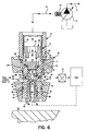
- the load sense cartridge comprises a body 31 in the form of a barrel having external threads 32 for threading in the threaded portion 33 of the bore 23A and an unthreaded end portion 34 which is received within a smooth bore portion 35 aligned with the threaded bore 23A (see FIG. 4).
- the unthreaded end portion 34 has a groove 40 therein which receives an O-ring 42 so as to seal with the smooth bore 35.
- a reduced diameter portion 44 which is communication with the load sense passage 23. Threaded within a threaded bore 46 of the body 31 is a first plug 48.
- the first plug 48 has a hexagonal opening 49 therein for turning the plug to thread into the threaded bore 46, which hexagonal opening communicates the cartridge 12 with the pressure compensator 16 of pump 15 via line 14.
- the hexagonal opening 49 through the plug 48 communicates with an axial bore 50 that is in turn in communication with a radial bore 52.
- the plug has an end face 54 which projects into a smooth bore 56 in the body 31.
- a seal 57 seals the end face 54 from fluid communication with the rest of the plug 48.
- the plug 48 has a first narrow portion 62 which is spaced from an interior surface 64 inboard of the threaded bore 46 that defines an annular space 66 that communicates with a bore 68 which communicates with the passageway 23 so that when the cartridge is in the non-bleed off mode of FIG. 6, hydraulic fluid passes into the passageway 23, through the bore 68 and plug 48, over the line 14 and to the pressure compensator 16 of the pump 15. As is seen in FIG. 6, the end face 54 of the plug 48 abuts the end face 70 of a piston 72.
- the piston 72 has an axially extending first passage therein comprised of the first wide portion 73, a narrowed portion 74, and a narrower still pressure controlling orifice 75, which forms a flow limiter that opens into the bottom of an inverted cup 76.
- the piston 72 has a second annular end face 78 which in FIG. 6 faces and in FIG. 7 abuts an end 80 of a second plug 82 that is threaded into a threaded bore 84 of the barrel formed by the body 31.
- the second plug 82 has a cup portion 86 and a smooth bore 88 that communicates through a hexagonal opening 89 to the exhaust passage 22 that leads to "tank".
- Seated within the cup 86 is a coil spring 90 having a first end 91 that is received within the cup 76 of the piston 72 to normally bias the face 70 of the piston against the end face 54 of the first plug 48 with a selected force.
- the specific size of the pressure controlling orifice 75 can be varied to accommodate the specific system in which it is used.
- the diameter of the orifice 75 can be increased so as to make it less contamination sensitive and therefore less likely to clog.
Landscapes
- Engineering & Computer Science (AREA)
- General Engineering & Computer Science (AREA)
- Mining & Mineral Resources (AREA)
- Civil Engineering (AREA)
- Structural Engineering (AREA)
- Physics & Mathematics (AREA)
- Fluid Mechanics (AREA)
- Mechanical Engineering (AREA)
- Fluid-Pressure Circuits (AREA)
- Safety Valves (AREA)
Applications Claiming Priority (2)
| Application Number | Priority Date | Filing Date | Title |
|---|---|---|---|
| US09/212,246 US6089248A (en) | 1998-12-16 | 1998-12-16 | Load sense pressure controller |
| US212246 | 1998-12-16 |
Publications (2)
| Publication Number | Publication Date |
|---|---|
| EP1010896A2 true EP1010896A2 (de) | 2000-06-21 |
| EP1010896A3 EP1010896A3 (de) | 2003-01-02 |
Family
ID=22790203
Family Applications (1)
| Application Number | Title | Priority Date | Filing Date |
|---|---|---|---|
| EP99310015A Withdrawn EP1010896A3 (de) | 1998-12-16 | 1999-12-13 | Druckregler für Lastmeldedruck |
Country Status (2)
| Country | Link |
|---|---|
| US (1) | US6089248A (de) |
| EP (1) | EP1010896A3 (de) |
Families Citing this family (7)
| Publication number | Priority date | Publication date | Assignee | Title |
|---|---|---|---|---|
| NL1012064C2 (nl) * | 1999-05-14 | 2000-11-20 | Applied Power Inc | Afdekkapsamenstel met hydraulische bedieningsinrichting. |
| CN1274810A (zh) * | 1999-05-21 | 2000-11-29 | 株式会社岛津制作所 | 多阀门装置 |
| US7261030B2 (en) * | 2004-09-09 | 2007-08-28 | Hydraforce, Inc. | Method and system for improving stability of hydraulic systems with load sense |
| US7636053B2 (en) * | 2006-09-20 | 2009-12-22 | Toyota Motor Engineering & Manufacturing North America, Inc. | Article and method for monitoring temperature and pressure within a pressurized gas cylinder |
| DE102006060333B3 (de) * | 2006-12-20 | 2008-08-21 | Sauer-Danfoss Aps | Hydraulische Ventilanordnung |
| BR112017008921B1 (pt) * | 2014-10-30 | 2022-05-31 | Xuzhou Heavy Machinery Co., Ltd | Sistema hidráulico de guindaste e método de controle do sistema |
| US10808733B2 (en) | 2019-03-05 | 2020-10-20 | Deere & Company | Open center to open center load sense conversion valve and hydraulic systems therewith |
Family Cites Families (13)
| Publication number | Priority date | Publication date | Assignee | Title |
|---|---|---|---|---|
| US30828A (en) * | 1860-12-04 | Improvement in fountain-pens | ||
| US3841096A (en) * | 1971-06-29 | 1974-10-15 | H Metz | Control and regulator device for a load-independent regulated hydraulic system |
| US4020867A (en) * | 1974-08-26 | 1977-05-03 | Nisshin Sangyo Kabushiki Kaisha | Multiple pressure compensated flow control valve device of parallel connection used with fixed displacement pump |
| DE2442279A1 (de) * | 1974-09-04 | 1976-03-18 | Nisshin Sangyo K K | Steuervorrichtung zum steuern des flusses der druckfluessigkeit zu einer mehrzahl von hydraulischen stellgliedern |
| GB1555118A (en) * | 1975-10-04 | 1979-11-07 | Lucas Industries Ltd | Servo pressure control arrangements for variable stroke pumps |
| DE2551088C2 (de) * | 1975-11-14 | 1984-06-28 | Mannesmann Rexroth GmbH, 8770 Lohr | Vorrichtung zur Mengen- und Druckregelung für Verstellpumpen |
| US4344285A (en) * | 1980-02-04 | 1982-08-17 | The Cessna Aircraft Company | Signal bleed-down valve |
| DE3346182A1 (de) * | 1983-12-21 | 1985-07-04 | Mannesmann Rexroth GmbH, 8770 Lohr | Stromregelventil fuer ein wegeventil |
| DE3515732A1 (de) * | 1985-05-02 | 1986-11-06 | Danfoss A/S, Nordborg | Steuereinrichtung fuer mindestens einen hydraulisch betriebenen verbraucher |
| FR2689575B1 (fr) * | 1992-04-06 | 1994-07-08 | Rexroth Sigma | Distributeur hydraulique a compensation de pression et une selection de pression maximale pour piloter une pompe et commande hydraulique multiple incluant de tels distributeurs. |
| DE4211817A1 (de) * | 1992-04-08 | 1993-10-14 | Danfoss As | Drucksteuerventil |
| US5454223A (en) * | 1993-05-28 | 1995-10-03 | Dana Corporation | Hydraulic load sensing system with poppet valve having an orifice therein |
| US5878766A (en) * | 1997-10-20 | 1999-03-09 | Vickers, Incorporated | Pressure compensated flow control valve |
-
1998
- 1998-12-16 US US09/212,246 patent/US6089248A/en not_active Expired - Lifetime
-
1999
- 1999-12-13 EP EP99310015A patent/EP1010896A3/de not_active Withdrawn
Non-Patent Citations (1)
| Title |
|---|
| None |
Also Published As
| Publication number | Publication date |
|---|---|
| EP1010896A3 (de) | 2003-01-02 |
| US6089248A (en) | 2000-07-18 |
Similar Documents
| Publication | Publication Date | Title |
|---|---|---|
| US5878647A (en) | Pilot solenoid control valve and hydraulic control system using same | |
| EP0468944B1 (de) | Einrichtung zur Steuerung hydraulischer Motoren | |
| US5579642A (en) | Pressure compensating hydraulic control system | |
| US5333449A (en) | Pressure compensating valve assembly | |
| US6073652A (en) | Pilot solenoid control valve with integral pressure sensing transducer | |
| US5533334A (en) | Pressurized fluid supply system | |
| US5193342A (en) | Proportional speed control of fluid power devices | |
| US6502500B2 (en) | Hydraulic system for a work machine | |
| US5845678A (en) | Pressurized fluid supply system | |
| US5567123A (en) | Pump displacement control for a variable displacement pump | |
| US4599050A (en) | Device for controlling displacement of variable displacement hydraulic pump | |
| US6089248A (en) | Load sense pressure controller | |
| US4196588A (en) | Margin valve | |
| US4028890A (en) | Piston pump assembly utilizing load pressure control | |
| CA1077344A (en) | Load plus differential pressure compensator pump control assembly | |
| GB2294558A (en) | Capacity control device for variable capacity hydraulic pump | |
| JPS6214718B2 (de) | ||
| JP2649181B2 (ja) | 可変排除量ポンプの自動制御装置 | |
| CA2224214A1 (en) | Hydraulic valve to maintain control in fluid-loss condition | |
| US5735311A (en) | Pressure compensation valve | |
| US4942900A (en) | Pressure control valve | |
| US5562424A (en) | Pump displacement control for a variable displacement pump | |
| EP0080135A1 (de) | Hydraulisches Steuersystem für ein hydraulisches Stellglied | |
| EP0056369B1 (de) | Druckminderventil für das lastabsenken ohne motorbetrieb | |
| US6030183A (en) | Variable margin pressure control |
Legal Events
| Date | Code | Title | Description |
|---|---|---|---|
| PUAI | Public reference made under article 153(3) epc to a published international application that has entered the european phase |
Free format text: ORIGINAL CODE: 0009012 |
|
| AK | Designated contracting states |
Kind code of ref document: A2 Designated state(s): AT BE CH CY DE DK ES FI FR GB GR IE IT LI LU MC NL PT SE |
|
| AX | Request for extension of the european patent |
Free format text: AL;LT;LV;MK;RO;SI |
|
| RAP1 | Party data changed (applicant data changed or rights of an application transferred) |
Owner name: PARKER HANNIFIN CORPORATION |
|
| PUAL | Search report despatched |
Free format text: ORIGINAL CODE: 0009013 |
|
| AK | Designated contracting states |
Kind code of ref document: A3 Designated state(s): AT BE CH CY DE DK ES FI FR GB GR IE IT LI LU MC NL PT SE |
|
| AX | Request for extension of the european patent |
Free format text: AL;LT;LV;MK;RO;SI |
|
| 17P | Request for examination filed |
Effective date: 20030630 |
|
| AKX | Designation fees paid |
Designated state(s): DE GB IT SE |
|
| 17Q | First examination report despatched |
Effective date: 20031114 |
|
| GRAP | Despatch of communication of intention to grant a patent |
Free format text: ORIGINAL CODE: EPIDOSNIGR1 |
|
| STAA | Information on the status of an ep patent application or granted ep patent |
Free format text: STATUS: THE APPLICATION IS DEEMED TO BE WITHDRAWN |
|
| 18D | Application deemed to be withdrawn |
Effective date: 20060614 |