EP1010608A2 - Hydraulic damping system for the rotary motion of rotating joint between two vehicle parts of articulated vehicles, for example articulated buses - Google Patents
Hydraulic damping system for the rotary motion of rotating joint between two vehicle parts of articulated vehicles, for example articulated buses Download PDFInfo
- Publication number
- EP1010608A2 EP1010608A2 EP99124739A EP99124739A EP1010608A2 EP 1010608 A2 EP1010608 A2 EP 1010608A2 EP 99124739 A EP99124739 A EP 99124739A EP 99124739 A EP99124739 A EP 99124739A EP 1010608 A2 EP1010608 A2 EP 1010608A2
- Authority
- EP
- European Patent Office
- Prior art keywords
- pressure relief
- relief valve
- valve
- hydraulic
- articulated
- Prior art date
- Legal status (The legal status is an assumption and is not a legal conclusion. Google has not performed a legal analysis and makes no representation as to the accuracy of the status listed.)
- Granted
Links
Images

Classifications
-
- B—PERFORMING OPERATIONS; TRANSPORTING
- B62—LAND VEHICLES FOR TRAVELLING OTHERWISE THAN ON RAILS
- B62D—MOTOR VEHICLES; TRAILERS
- B62D47/00—Motor vehicles or trailers predominantly for carrying passengers
- B62D47/02—Motor vehicles or trailers predominantly for carrying passengers for large numbers of passengers, e.g. omnibus
- B62D47/025—Motor vehicles or trailers predominantly for carrying passengers for large numbers of passengers, e.g. omnibus articulated buses with interconnecting passageway, e.g. bellows
-
- B—PERFORMING OPERATIONS; TRANSPORTING
- B62—LAND VEHICLES FOR TRAVELLING OTHERWISE THAN ON RAILS
- B62D—MOTOR VEHICLES; TRAILERS
- B62D53/00—Tractor-trailer combinations; Road trains
Definitions
- the invention relates to a hydraulic system for damping the Rotational movement of a swivel joint between two vehicle parts Articulated vehicle, e.g. an articulated bus and a swivel with one such hydraulic system.
- Articulated vehicle e.g. an articulated bus and a swivel with one such hydraulic system.
- a swivel joint of the type mentioned is from the prior art known.
- Such a swivel joint known from the prior art includes two articulated links that can be pivoted through an axis are interconnectable.
- One articulated member can do this directly be articulated on one vehicle or vehicle part, whereas that other joint member pivotable about a horizontal axis directly with the vehicle or vehicle part or indirectly through a Intermediate member can be connected to the vehicle or vehicle part.
- This horizontal axis takes into account the fact that the Swivel joint also pitch movements of the two vehicles relative to each other must be able to yield.
- At these swivel joints is after a first one Embodiment on both sides of the longitudinal axis of the vehicle or of the swivel joint, a hydraulic cylinder is provided, the Hydraulic cylinder on the one hand with a link and on the other connected to the vehicle.
- the orientation of the Attenuators are in relation to the central longitudinal axis of the Vehicles angled.
- one is double acting Hydraulic cylinder provided, which is oriented transversely to the longitudinal axis on Swivel is attached.
- the electrical control of such a hydraulic system is known; here is an electrically controllable proportional pressure relief valve provided that between the pressure and the suction side of the double-acting Hydraulic cylinder or between the pressure and the suction side of the two single-acting hydraulic cylinders is arranged. Through a such a proportional pressure relief valve is achieved that the Flow resistance of the hydraulic medium is increased.
- the consequence of this is - how already executed - a damping in the movement of the joint when buckling, for example when cornering.
- Such damping at the rotational movement of the two joint members relative to one another is absolute necessary because otherwise the vehicle is difficult to control.
- Articulated vehicles of this type are often designed as so-called pushers; A pusher is a vehicle with the last axle is driven.
- this proportional pressure relief valve depends on the vehicle condition, with influences such as the Speed of the vehicle and the position of the Front of the vehicle to the rear of the vehicle are taken into account. If the hydraulic system fails at higher speeds, for example by interrupting the circuit, then must Ensure that the vehicle brakes at least safely and the next one at a greatly reduced speed Repair workshop can start.
- the invention is therefore based on the object of a hydraulic system type mentioned at the outset in such a way that even if the electrical system of a vehicle associated with it Damping effect during the rotational movement of the two joint members Joint relative to each other due to failure of the proportional pressure relief valve it is ensured that the vehicle is in one manageable condition remains.
- a mechanical one Pressure relief valve is provided, with a multi-way valve for optional control of the pressure relief valve or the Proportional pressure relief valve is provided.
- a mechanical one Pressure relief valve is provided in the line between the suction and the pressure side of the damping device in addition to the proportional pressure relief valve, with a multi-way valve for optional control of the pressure relief valve or the Proportional pressure relief valve is provided.
- Such a thing Pressure relief valve is designed so that it is on a predetermined pressure drop is adjustable. That is, the mechanical Pressure relief valve can be set to a certain minimum pressure, which - as already explained - determines the degree of damping.
- the mechanical pressure relief valve in parallel or in series with the Electrically operating proportional pressure relief valve in the line between the suction and the pressure side of the damping device is arranged.
- the hydraulic Damping arrangement a double-acting piston-cylinder arrangement comprises, or two piston-cylinder arrangements according to another Embodiment.
- Such a double-acting piston cylinder arrangement in installed transversely to the longitudinal direction of the vehicle gives the advantage of more compact design.
- the mechanical Pressure relief valve a multi-way valve and here in particular a 3/2-way valve with a parallel connection of the proportional pressure relief valve and mechanical pressure relief valve or a 2/2-way valve if the pressure relief valves are arranged in series.
- the invention also relates to a joint of an articulated vehicle with a hydraulic system as described above.
- Swivel joint two joint members 10, 20 are provided, which are at the break point 30 are rotatably connected to one another, for example by a bolt.
- the articulated member 20 can here directly on the 21 indicated vehicle be articulated, whereas the articulated member 10th can be swiveled by a horizontal axis, if necessary by an intermediate link to which the vehicle 11 is connected. Such Connection is necessary to prevent pitching movements of the two vehicles 11, 21 to enable relative to each other.
- the invention now relates to the circuit, namely as Series connection or parallel connection of the proportional pressure relief valve to the mechanical pressure relief valve.
- valve 104 fails, the piston turns in when the piston moves Direction of arrow 110 shows how it works: Valve 104 is open in the event of such a malfunction; the fluid in the line 109b is supplied to the valve 103, the line 109c is through the 2/2-way valve 102b blocked. The piston 101 moves in In the direction of arrow 110a, the fluid flow is corresponding vice versa.
- the pressure relief valve 103 is designed such that it only at a predeterminable pressure of the fluid in the direction of the arrow 108 lets through. That is, it happens when the piston 101 moves Direction of arrow 110a:
- the fluid is forced out of the chamber 100b and passes through the Line 105 and 109b to the 2/2-way valve 102b and that Pressure relief valve 103.
- the 2/2-way valve 102b blocks, so that builds up a pressure before the pressure relief valve 103.
- With enough high pressure in the direction of arrow 108 is the pressure relief valve permeable and the fluid passes through the non-activated, i.e. open Proportional pressure relief valve 104 into chamber 100a. in this connection damping takes place due to the pressure drop at valve 103.
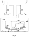
- a 3/2-way valve 102a is provided, a Proportional pressure relief valve 104 and a mechanical Pressure relief valve 103.
- valve 104 When the valve 104 is in operation, the piston 101 moves in Direction of arrow 110a the flow of the hydraulic medium from the chamber 100b through lines 144, 150 and 140 through valve 104 line 160 into chamber 100a.
- the line 145 is here through 3/2-way valve 102a shut off.
Abstract
Description
Die Erfindung betrifft eine Hydraulikanlage für die Dämpfung der Drehbewegung eines Drehgelenkes zwischen zwei Fahrzeugteilen eines Gelenkfahrzeuges, z.B. eines Gelenkbusses und ein Drehgelenk mit einer derartigen Hydraulikanlage. The invention relates to a hydraulic system for damping the Rotational movement of a swivel joint between two vehicle parts Articulated vehicle, e.g. an articulated bus and a swivel with one such hydraulic system.
Ein Drehgelenk der eingangs genannten Art ist aus dem Stand der Technik bekannt. Ein derartiges aus dem Stand der Technik bekanntes Drehgelenk umfasst zwei Gelenkglieder, die durch eine Achse verschwenkbar miteinander verbindbar sind. Das eine Gelenkglied kann hierbei unmittelbar an dem einen Fahrzeug bzw. Fahrzeugteil angelenkt sein, wohingegen das andere Gelenkglied um eine horizontal verlaufende Achse schwenkbar unmittelbar mit dem Fahrzeug bzw. Fahrzeugteil oder mittelbar durch ein Zwischenglied mit dem Fahrzeug bzw. Fahrzeugteil verbindbar ist. Durch diese horizontale Achse wird der Tatsache Rechnung getragen, dass das Drehgelenk auch Nickbewegungen der beiden Fahrzeuge relativ zueinander nachgeben können muss. Bei diesen Drehgelenken ist nach einer ersten Ausführungsform zu beiden Seiten der Längsachse des Fahrzeuges bzw. des Drehgelenkes jeweils ein Hydraulikzylinder vorgesehen, wobei die Hydraulikzylinder zum einen mit dem einen Gelenkglied und zum anderen mit dem Fahrzeug in Verbindung stehen. Die Ausrichtung der Dämpfungsglieder ist hierbei in Bezug auf die Mittellängsachse der Fahrzeuge winklig.A swivel joint of the type mentioned is from the prior art known. Such a swivel joint known from the prior art includes two articulated links that can be pivoted through an axis are interconnectable. One articulated member can do this directly be articulated on one vehicle or vehicle part, whereas that other joint member pivotable about a horizontal axis directly with the vehicle or vehicle part or indirectly through a Intermediate member can be connected to the vehicle or vehicle part. By this horizontal axis takes into account the fact that the Swivel joint also pitch movements of the two vehicles relative to each other must be able to yield. At these swivel joints is after a first one Embodiment on both sides of the longitudinal axis of the vehicle or of the swivel joint, a hydraulic cylinder is provided, the Hydraulic cylinder on the one hand with a link and on the other connected to the vehicle. The orientation of the Attenuators are in relation to the central longitudinal axis of the Vehicles angled.
Bei einer anderen Ausführungsform ist ein doppelt wirkender Hydraulikzylinder vorgesehen, der quer zur Längsachse ausgerichtet am Drehgelenk befestigt ist.In another embodiment, one is double acting Hydraulic cylinder provided, which is oriented transversely to the longitudinal axis on Swivel is attached.
Bekannt ist die elektrische Ansteuerung einer derartigen Hydraulikanlage; hierbei ist ein elektrisch ansteuerbares Proportionaldruck-Begrenzungsventil vorgesehen, das zwischen der Druck- und der Saugseite des doppeltwirkenden Hydraulikzylinders bzw. zwischen der Druck- und der Saugseite der beiden einfachwirkenden Hydraulikzylinder angeordnet ist. Durch ein derartiges Proportionaldruck-Begrenzungsventil wird erreicht, dass der Fließwiderstand des Hydraulikmediums erhöht wird. Die Folge hiervon ist - wie bereits ausgeführt - eine Dämpfung in der Bewegung des Gelenkes beim Einknicken, beispielsweise bei Kurvenfahrt. Eine solche Dämpfung bei der Drehbewegung der beiden Gelenkglieder relativ zueinander ist absolut notwendig, da ansonsten das Fahrzeug nur schwer beherrschbar ist. Derartige Gelenkfahrzeuge sind häufig als sogenannte Pusher ausgebildet; unter einem Pusher versteht man ein Fahrzeug, bei dem die letzte Achse angetrieben ist. Versagt nun die Hydraulikanlage, d. h. findet keine Dämpfung bei der Drehbewegung der beiden Gelenkglieder relativ zueinander statt, dann kann bei höheren Geschwindigkeiten schon bei geringem Lenkeinschlag das Fahrzeug ausbrechen, da der Hinterwagen den Vorderwagen über die Querachse wegschiebt. Gleiches passiert bei Geradeausfahrt, wenn die Straße Spurrillen aufweist. Hierbei kann sich das Fahrzeug autschaukeln. Das heißt, ein Ausfall der Hydraulikanlage ist insbesondere dann zu konstatieren, wenn das elektrisch ansteuerbare Proportionaldruck-Begrenzungsventil ausfällt. Dies ist dann der Fall, wenn die Stromversorgung des Fahrzeugs unterbrochen ist, da die Steuerung des Proportionaldruck-Begrenzungsventils über elektrische Signale erfolgt. Die elektrische Ansteuerung und damit einhergehend der Grad der Dämpfung dieses Proportionaldruck-Begrenzungsventils erfolgt in Abhängigkeit von dem Fahrzeugzustand, wobei Einflüsse wie beispielsweise die Geschwindigkeit des Fahrzeuges und die Stellung des Fahrzeugvorderwagens zum Fahrzeughinterwagen berücksichtigt werden. Fällt demzufolge bei höheren Geschwindigkeiten die Hydraulikanlage aus, beispielsweise dadurch, dass der Stromkreis unterbrochen ist, dann muss sichergestellt sein, dass das Fahrzeug zumindest gefahrlos abgebremst werden und mit stark verminderter Geschwindigkeit gefahrlos die nächste Reparaturwerkstätte anfahren kann.The electrical control of such a hydraulic system is known; here is an electrically controllable proportional pressure relief valve provided that between the pressure and the suction side of the double-acting Hydraulic cylinder or between the pressure and the suction side of the two single-acting hydraulic cylinders is arranged. Through a such a proportional pressure relief valve is achieved that the Flow resistance of the hydraulic medium is increased. The consequence of this is - how already executed - a damping in the movement of the joint when buckling, for example when cornering. Such damping at the rotational movement of the two joint members relative to one another is absolute necessary because otherwise the vehicle is difficult to control. Articulated vehicles of this type are often designed as so-called pushers; A pusher is a vehicle with the last axle is driven. Now the hydraulic system fails, i.e. H. finds none Damping relative to the rotational movement of the two joint members to each other instead, then at higher speeds already at small steering lock break out the vehicle because the rear end of the Pushes the front end over the transverse axis. The same thing happens with Straight ahead when the road has ruts. This can be Swing the vehicle. That means there is a failure of the hydraulic system to be found in particular when the electrically controllable Proportional pressure relief valve fails. This is the case if the power supply to the vehicle is interrupted because the control of the Proportional pressure relief valve is done via electrical signals. The electrical control and the associated degree of damping this proportional pressure relief valve depends on the vehicle condition, with influences such as the Speed of the vehicle and the position of the Front of the vehicle to the rear of the vehicle are taken into account. If the hydraulic system fails at higher speeds, for example by interrupting the circuit, then must Ensure that the vehicle brakes at least safely and the next one at a greatly reduced speed Repair workshop can start.
Der Erfindung liegt daher die Aufgabe zugrunde, eine Hydraulikanlage der eingangs genannten Art derart weiterzubilden, bei der selbst bei Ausfall der elektrischen Anlage eines Fahrzeuges damit einhergehend der Dämpfungswirkung bei der Drehbewegung der beiden Gelenkglieder eines Gelenkes relativ zueinander durch Ausfall des Proportionaldruck-Begrenzungsventiles sichergestellt ist, dass das Fahrzeug in einem beherrschbaren Zustand bleibt.The invention is therefore based on the object of a hydraulic system type mentioned at the outset in such a way that even if the electrical system of a vehicle associated with it Damping effect during the rotational movement of the two joint members Joint relative to each other due to failure of the proportional pressure relief valve it is ensured that the vehicle is in one manageable condition remains.
Die Aufgabe wird erfindungsgemäß dadurch gelöst, dass in der Leitung zwischen der Saug- und der Druckseite der Dämpfungseinrichtung zusätzlich zu dem Proportional-Druckbegrenzungsventil ein mechanisches Druckbegrenzungsventil vorgesehen ist, wobei ein Mehrwegeventil zur wahlweisen Aussteuerung des Druckbegrenzungsventils oder des Proportional-Druckbegrenzungsventils vorgesehen ist. Ein derartiges Druckbegrenzungsventil ist so ausgebildet, dass es auf einen vorbestimmten Druckabfall einstellbar ist. Das heißt, das mechanische Druckbegrenzungsventil ist auf einen bestimmten Mindestdruck einstellbar, der -wie bereits erläutert- den Grad der Dämpfung bestimmt.The object is achieved in that in the line between the suction and the pressure side of the damping device in addition to the proportional pressure relief valve, a mechanical one Pressure relief valve is provided, with a multi-way valve for optional control of the pressure relief valve or the Proportional pressure relief valve is provided. Such a thing Pressure relief valve is designed so that it is on a predetermined pressure drop is adjustable. That is, the mechanical Pressure relief valve can be set to a certain minimum pressure, which - as already explained - determines the degree of damping.
Hierbei kann nach zwei Ausführungsformen vorgesehen sein, dass das mechanische Druckbegrenzungsventil parallel oder in Reihe zu dem elektrisch arbeitenden Proportional-Druckbegrenzungsventil in der Leitung zwischen der Saug- und der Druckseite der Dämpfungseinrichtung angeordnet ist.It can be provided according to two embodiments that the mechanical pressure relief valve in parallel or in series with the Electrically operating proportional pressure relief valve in the line between the suction and the pressure side of the damping device is arranged.
Im Einzelnen ist weiterhin vorgesehen, dass die hydraulische Dämpfungsanordnung eine doppeltwirkende Kolbenzylinderanordnung umfasst, bzw. zwei Kolbenzylinderanordnungen nach einer weiteren Ausführungsform. Eine solche doppeltwirkende Kolbenzylinderanordnung in quer zur Fahrzeuglängsrichtung eingebautem Zustand ergibt den Vorteil der kompakteren Bauweise.In particular, it is also provided that the hydraulic Damping arrangement a double-acting piston-cylinder arrangement comprises, or two piston-cylinder arrangements according to another Embodiment. Such a double-acting piston cylinder arrangement in installed transversely to the longitudinal direction of the vehicle gives the advantage of more compact design.
Um zu gewährleisten, dass bei nicht mehr funktionsfähigem Proportional-Druckbegrenzungsventil und mithin bei offengeschaltetem Proportional-Druckbegrenzungsventil der hydraulische Pfad über das mechanische Druckbegrenzungsventil verläuft, ist dem mechanischen Druckbegrenzungsventil ein Mehrwegeventil und hier insbesondere ein 3/2-Wegeventil bei einer Parallelschaltung von Proportional-Druckbegrenzungsventil und mechanischem Druckbegrenzungsventil bzw. ein 2/2-Wegeventil bei Anordnung der Druckbegrenzungsventile in Reihe.To ensure that when the proportional pressure relief valve is no longer functional and therefore with the proportional pressure relief valve open the hydraulic path via the mechanical Pressure relief valve runs is the mechanical Pressure relief valve a multi-way valve and here in particular a 3/2-way valve with a parallel connection of the proportional pressure relief valve and mechanical pressure relief valve or a 2/2-way valve if the pressure relief valves are arranged in series.
Weitere vorteilhafte Merkmale sind den Ansprüchen zu entnehmen.Further advantageous features can be found in the claims.
Gegenstand der Erfindung ist ebenfalls ein Gelenk eines Gelenkfahrzeuges mit einer Hydraulikanlage, wie sie zuvor beschrieben wurde.The invention also relates to a joint of an articulated vehicle with a hydraulic system as described above.
Anhand der Zeichnungen wird die Erfindung nachstehend beispielhaft näher erläutert:
- Figur 1
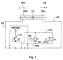
- zeigt schematisch die Reihenschaltung des Proportional-Druckbegrenzungsventiles mit dem mechanisch ansteuerbaren Druckbegrenzungsventil bei einem doppeltwirkenden Zylinder;
- Figur 2
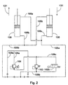
- zeigt schematisch eine Reihenschaltung gemäß Fig. 1 mit zwei einfachwirkenden Zylindern;
- Figur 3
- zeigt schematisch eine Parallelschaltung einer Hydraulikanlage mit doppeltwirkendem Zylinder;
- Figur 4
- zeigt schematisch eine Parallelschaltung gemäß Fig. 1 mit zwei einfachwirkenden Zylindern;
- Figur 5
- zeigt schematisch eine Draufsicht auf ein Gelenk mit zwei einfach wirkendenZylindern;
- Figur 6
- zeigt schematisch eine Draufsicht auf ein Gelenk mit einem doppeltwirkenden Zylinder.
- Figure 1
- shows schematically the series connection of the proportional pressure relief valve with the mechanically controllable pressure relief valve in a double-acting cylinder;
- Figure 2
- shows schematically a series circuit according to FIG 1 with two single-acting cylinders.
- Figure 3
- shows schematically a parallel connection of a hydraulic system with double-acting cylinder;
- Figure 4
- shows schematically a parallel connection according to Figure 1 with two single-acting cylinders.
- Figure 5
- schematically shows a top view of a joint with two single-acting cylinders;
- Figure 6
- shows schematically a plan view of a joint with a double-acting cylinder.
Bei dem in Figur 5 und Figur 6 dargestellten und mit 1 bezeichneten Drehgelenk sind zwei Gelenkglieder 10, 20 vorgesehen, die im Knickpunkt 30 drehbar miteinander, beispielsweise durch einen Bolzen, verbunden sind. Das Gelenkglied 20 kann hierbei unmittelbar an dem hier mit 21 angedeuteten Fahrzeug angelenkt sein, wohingegen das Gelenkglied 10 durch eine horizontal verlaufende Achse schwenkbar, gegebenenfalls durch ein Zwischenglied, mit dem Fahrzeug 11 verbunden ist. Eine solche Verbindung ist notwendig, um Nickbewegungen der beiden Fahrzeuge 11, 21 relativ zueinander zu ermöglichen.In the one shown in FIG. 5 and FIG. 6 and labeled 1 Swivel joint two joint members 10, 20 are provided, which are at the break point 30 are rotatably connected to one another, for example by a bolt. The articulated member 20 can here directly on the 21 indicated vehicle be articulated, whereas the articulated member 10th can be swiveled by a horizontal axis, if necessary by an intermediate link to which the vehicle 11 is connected. Such Connection is necessary to prevent pitching movements of the two vehicles 11, 21 to enable relative to each other.
Gegenstand der Erfindung ist nunmehr die Schaltung, und zwar als Reihenschaltung oder Parallelschaltung des Proportional-Druckbegrenzungsventile zu dem mechanischen Druckbegrenzungsventil.The invention now relates to the circuit, namely as Series connection or parallel connection of the proportional pressure relief valve to the mechanical pressure relief valve.
Wie aus Figur 1 erkennbar, ist hier eine Reihenschaltung bei einem doppeltwirkenden
Zylinder vorgesehen. Der insgesamt mit 100 bezeichnete
Zylinder mit den beiden Kammern 100a, 100b steht mit dem Kolben 101,
mit dem Proportional-Druckbegrenzungsventil 104, dem 2/2-Wegeventil
102b und dem mechanischen Druckbegrenzungsventil 103 durch die
Leitung 105 in Verbindung.As can be seen from Figure 1, here is a series connection with a double-acting
Cylinder provided. The total designated 100
Cylinder with the two
Für die Funktionsweise wird zunächst davon ausgegangen, dass der Kolben
101 der doppeltwirkenden Kolbenzylinderanordnung in Richtung des Pfeiles
110 läuft. Hierbei erhöht sich der Druck in der Kammer 100a, wohingegen
in der Kammer 100b der Druck entsprechend abnimmt. Die Folge hiervon
ist, dass durch das Proportional-Druckbegrenzungsventil im normalen
Zustand der Durchfluss des Fluides begrenzt wird, und damit das
Hydraulikfluid unter geringerem Druck durch die Leitungen 105 und 109a
der Kammer 100b des doppeltwirkenden Kolben-Zylinders zugeführt wird.
Bewegt sich der Kolben 101 in Richtung des Pfeiles 110a, dann ist der Lauf
des Fluids wie folgt: von der Kammer 100b in die Leitung 105 und durch
die Leitung 109b zu dem 2/2-Wegeventil 102b. Der Durchgang durch das
Ventil 103 findet nicht statt, weil dieses durch das 2/2 Wegeventil 102b
kurzgeschlossen ist.For the functioning it is initially assumed that the
Fällt das Ventil 104 aus, dann stellt sich bei Bewegung des Kolbens in
Richtung des Pfeiles 110 die Funktionsweise wie folgt dar: Das Ventil 104
ist bei einer solchen Funktionsstörung geöffnet; das Fluid in der Leitung
109b wird dem Ventil 103 zugeführt, die Leitung 109c ist durch das 2/2-Wegeventil
102b blockiert. Erfolgt die Bewegung des Kolbens 101 in
Richtung des Pfeiles 110a, dann ist der Fluidverlauf entsprechend
umgekehrt. Das Druckbegrenzungsventil 103 ist so ausgebildet, dass es
erst bei einem vorbestimmbaren Druck des Fluids in Richtung des Pfeiles
108 durchlässt. Das heißt, es geschieht bei Bewegung des Kolbens 101 in
Richtung des Pfeiles 110a Folgendes:If the
Das Fluid wird aus der Kammer 100b herausgedrückt und läuft durch die
Leitung 105 und 109b bis an das 2/2-Wegeventil 102b und das
Druckbegrenzungsventil 103. Das 2/2-Wegeventil 102b sperrt, so dass sich
vor dem Druckbegrenzungsventil 103 ein Druck aufbaut. Bei genügend
hohem Druck in Richtung des Pfeiles 108 ist das Druckbegrenzungsventil
durchlässig und das Fluid gelangt durch das nicht aktivierte, d.h. offene
Proportional-Druckbegrenzungsventil 104 in die Kammer 100a. Hierbei
findet aufgrund des Druckabfalls am Ventil 103 eine Dämpfung statt.The fluid is forced out of the
Die Funktionsweise der Reihenschaltung von zwei Zylindern gemäß Figur 2 ist wie folgt:The functioning of the series connection of two cylinders according to FIG. 2 is as follows:
Bei sich in Richtung des Pfeiles 121 des Kolbenzylinderantriebes 120 bzw.
in Richtung des Pfeiles 131 des Kolbenzylinderantriebes 130 aufbauendem
Druck ist der Fluss des Fluids durch die Leitungen 105a und 109b zu dem
2/2-Wegeventil 102b, durch die Leitung 109c zu dem Proportional-Druckbegrenzungsventil
104 auf die jeweils andere Seite (Saugseite) der
Kolbenzylinderanordnung 120, 130. Auch hier ist das Ventil 103 so
ausgebildet, dass es erst bei höherem Druck das Fluid durchlässt.With itself in the direction of
Für den Fall des Ausfalles des Proportional-Druckbegrenzungsventiles 104
ist der Fluss des Fluids wie folgt:In the event of failure of the proportional
Bei Druck in Richtung des Pfeiles 121 bzw. 131 der Kolbenzylinderanordnung
120, 130 steigt zunächst der Druck in den Leitungen 105a und
109b vor dem 2/2-Wegeventil 102b an, da das 2/2-Wegeventil für das
Fluid aus der Leitung 109b geschlossen ist. Bei Erreichen eines
vorbestimmten Druckes wird das Druckbegrenzungsventil 103 durchlässig,
so dass das Fluid durch das Ventil 103 und das geöffnete Proportional-Druckbegrenzungsventil
104 auf die entsprechende Saugseite der Zylinder
der Kolbenzylinderanordnung 120, 130 gelangen kann. Das Ventil 103
arbeitet in diesem Moment als Druckbegrenzer. Bei Stromausfall ist das
Ventil 104 geöffnet und das 2/2-Wegeventil 102b nicht durchlässig.With pressure in the direction of
Die Funktionsweise der Parallelschaltung mit einem doppeltwirkenden Zylinder gemäß Figur 3 stellt sich wie folgt dar:The operation of the parallel connection with a double-acting The cylinder according to FIG. 3 is as follows:
Bei der Parallelschaltung ist ein 3/2-Wegeventil 102a vorgesehen, ein
Proportional-Druckbegenzungsventil 104 und ein mechanisches
Druckbegrenzungsventil 103.In the parallel connection, a 3/2-
Bei funktionierendem Proportional-Druckbegrenzungsventil 104 ist bei
Bewegung des Kolbens 101 des doppeltwirkenden Kolbenzylinders 100 in
Richtung des Pfeiles 110 der Fluss des Fluids von der Kammer 100a durch
das 3/2-Wegeventil 102a, durch die Leitung 140, durch das Proportional-Druckbegrenzungsventil
104 hindurch in die Kammer 100b (Saugseite) der
Zylinder der jeweiligen Kolbenzylinderanordnung. When the proportional
Fällt nunmehr das Proportional-Druckbegrenzungsventil 104 aus, dann ist
die Leitung 140 durch das 3/2-Wegeventil 102a gesperrt, so dass das Fluid
von der Kammer 100a durch die Leitungen 145 und 146 durch das
mechanische Druckbegrenzungsventil 103 in die Kammer 100b gelangt.If the proportional
Gleiches gilt umgekehrt bei Bewegung des Kolbens 101 in Richtung des
Pfeiles 110a bei nicht funktionierendem, das heisst offenem Ventil 104.
Hierbei erfolgt der Fluss durch die Leitungen 150 und 145 in Richtung auf
das Ventil 103 und durch die Leitung 146 in die Kammer 100a.The same applies conversely when the
Bei funktionsfähigem Ventil 104 erfolgt bei Bewegung des Kolbens 101 in
Richtung des Pfeiles 110a der Fluss des Hydraulikmediums von der Kammer
100b durch die Leitungen 144, 150 und 140 durch das Ventil 104 durch
die Leitung 160 in die Kammer 100a. Die Leitung 145 ist hierbei durch das
3/2-Wegeventil 102a abgesperrt.When the
Nichts anderes ergibt sich aus der Darstellung gemäß Figur 4, wobei hier zwei einfachwirkende Kolbenzylinderanordnungen vorgesehen sind.Nothing else results from the illustration according to FIG. 4, whereby here two single-acting piston-cylinder arrangements are provided.
Claims (9)
dadurch gekennzeichnet,
dass in der Leitung zwischen der Saug- und der Druckseite der Dämpfungseinrichtung zusätzlich zu dem Proportional-Druckbegrenzungsventil (104) ein mechanisches Druckbegrenzungsventil (103) vorgesehen ist, wobei ein Mehrwegeventil zur wahlweisen Ansteuerung des Druckbegrenzungsventils (103) oder des Proportional-Druckbegrenzungsventils (104) vorgesehen ist.Hydraulic system for damping the rotary movement of a swivel joint between two vehicle parts of an articulated vehicle, e.g. B. an articulated bus, comprising a hydraulic damping arrangement and an electrically controllable proportional pressure relief valve, the proportional pressure relief valve being arranged between the pressure side and the suction side of the damping arrangement,
characterized,
that a mechanical pressure relief valve (103) is provided in the line between the suction and the pressure side of the damping device in addition to the proportional pressure relief valve (104), a multi-way valve for selectively actuating the pressure relief valve (103) or the proportional pressure relief valve (104) is provided.
dadurch gekennzeichnet,
dass das mechanische Druckbegrenzungsventil (103) parallel zu dem elektrisch ansteuerbaren Proportional-Druckbegrenzungsventil (104) angeordnet ist.Hydraulic system according to claim 1,
characterized,
that the mechanical pressure relief valve (103) is arranged parallel to the electrically controllable proportional pressure relief valve (104).
dadurch gekennzeichnet,
dass das mechanische Druckbegrenzungsventil (103) in Reihe zu dem elektrisch ansteuerbaren Proportional-Druckbegrenzungsventil (104) angeordnet ist. Hydraulic system according to claim 1,
characterized,
that the mechanical pressure relief valve (103) is arranged in series with the electrically controllable proportional pressure relief valve (104).
dadurch gekennzeichnet,
dass bei einer Reihenschaltung des Ventiles (103) mit dem Ventil (104) parallel zu dem mechanischen Druckbegrenzungsventil (103) das Wegeventil (102b) angeordnet ist.Hydraulic arrangement according to claim 3,
characterized,
that when the valve (103) is connected in series with the valve (104), the directional valve (102b) is arranged parallel to the mechanical pressure relief valve (103).
dadurch gekennzeichnet,
dass bei einer Parallelschaltung des Ventils (103) mit dem Ventil (104) ein Wegeventil (102a) den Ventilen (103, 104) vorgeschaltet ist.Hydraulic arrangement according to claim 2,
characterized,
that when the valve (103) is connected in parallel with the valve (104), a directional valve (102a) is connected upstream of the valves (103, 104).
dadurch gekennzeichnet,
dass die hydraulische Dämpfungsanordnung eine doppeltwirkende Kolbenzylinderanordnung (100) umfasst.Hydraulic system according to claim 4,
characterized,
that the hydraulic damping arrangement comprises a double-acting piston-cylinder arrangement (100).
dadurch gekennzeichnet,
dass die hydraulische Dämpfungsanordnung zwei Kolbenzylinderanordnungen (120, 130) umfasst.Hydraulic arrangement according to claim 4 or 5,
characterized,
that the hydraulic damping arrangement comprises two piston-cylinder arrangements (120, 130).
dadurch gekennzeichnet,
dass die hydraulische Dämpfungsanordnung eine doppeltwirkende Kolbenzylinderanordnung (100) umfasst.Hydraulic arrangement according to claim 5,
characterized,
that the hydraulic damping arrangement comprises a double-acting piston-cylinder arrangement (100).
gekennzeichnet durch
eine Hydraulikanlage gemäß einem oder mehreren der Ansprüche 1 bis 9.Swivel joint of an articulated vehicle,
marked by
a hydraulic system according to one or more of claims 1 to 9.
Applications Claiming Priority (2)
| Application Number | Priority Date | Filing Date | Title |
|---|---|---|---|
| DE29822472U | 1998-12-18 | ||
| DE29822472U DE29822472U1 (en) | 1998-12-18 | 1998-12-18 | Hydraulic system for damping the rotary movement of a swivel joint between two vehicle parts of an articulated vehicle, e.g. an articulated bus |
Publications (3)
| Publication Number | Publication Date |
|---|---|
| EP1010608A2 true EP1010608A2 (en) | 2000-06-21 |
| EP1010608A3 EP1010608A3 (en) | 2002-01-16 |
| EP1010608B1 EP1010608B1 (en) | 2004-03-24 |
Family
ID=8066766
Family Applications (1)
| Application Number | Title | Priority Date | Filing Date |
|---|---|---|---|
| EP99124739A Expired - Lifetime EP1010608B1 (en) | 1998-12-18 | 1999-12-13 | Hydraulic damping system for the rotary motion of rotating joint between two vehicle parts of articulated vehicles, for example articulated buses |
Country Status (4)
| Country | Link |
|---|---|
| US (1) | US6422584B1 (en) |
| EP (1) | EP1010608B1 (en) |
| AT (1) | ATE262441T1 (en) |
| DE (2) | DE29822472U1 (en) |
Cited By (2)
| Publication number | Priority date | Publication date | Assignee | Title |
|---|---|---|---|---|
| EP3587149A1 (en) | 2018-06-29 | 2020-01-01 | Scania CV AB | Articulated vehicle and method |
| EP3708454A1 (en) * | 2019-03-11 | 2020-09-16 | ALSTOM Transport Technologies | Railway vehicle comprising a system for semi-active damping and associated circulation method |
Families Citing this family (13)
| Publication number | Priority date | Publication date | Assignee | Title |
|---|---|---|---|---|
| US20020195795A1 (en) * | 2001-05-03 | 2002-12-26 | Brown David John Bowes | Vehicle with trailer |
| DE10209354A1 (en) * | 2002-03-02 | 2003-09-25 | Huebner Gmbh | Hinge between two articulated vehicles or vehicle parts of an articulated vehicle |
| US7412315B2 (en) * | 2002-08-30 | 2008-08-12 | Timberjack, Inc. | Steering system for articulated vehicles |
| US7261312B1 (en) * | 2003-04-11 | 2007-08-28 | Joplin Benjamin P | Trailer stabilization and weight distribution device |
| US7354056B2 (en) * | 2003-05-23 | 2008-04-08 | General Motors Corporation | Trailer stability control apparatus |
| US7175194B2 (en) * | 2004-10-06 | 2007-02-13 | Impact Engineering Technologies, Inc | Anti-jackknife system |
| US7874572B2 (en) | 2005-01-10 | 2011-01-25 | Energy Absorption Systems, Inc. | Towable impact attenuator |
| SE530628C3 (en) * | 2006-12-12 | 2008-08-19 | Scania Cv Ab | articulation control |
| DE202010016813U1 (en) * | 2010-12-20 | 2012-03-26 | Liebherr-Aerospace Lindenberg Gmbh | joint |
| CN103195855B (en) * | 2013-04-28 | 2015-05-20 | 伊卡路斯(苏州)车辆系统有限公司 | Hydraulic buffer system for rotary dampers |
| WO2015109611A1 (en) * | 2014-01-23 | 2015-07-30 | 伊卡路斯(苏州)车辆系统有限公司 | Hydraulic damping control system in articulated bus and corresponding bus articulation system |
| DE102015101032A1 (en) * | 2015-01-26 | 2016-07-28 | Amazonen-Werke H. Dreyer Gmbh & Co. Kg | Agricultural machine and regulatory procedure |
| DE102017100395A1 (en) | 2017-01-11 | 2018-07-12 | Claas Industrietechnik Gmbh | Hydraulic damping system and articulated vehicle with such a damping system |
Family Cites Families (15)
| Publication number | Priority date | Publication date | Assignee | Title |
|---|---|---|---|---|
| US4313616A (en) * | 1979-05-18 | 1982-02-02 | Howard D U | Speed responsive trailer stabilizer with zero slack |
| GR79630B (en) * | 1982-08-18 | 1984-10-31 | Falkenried Fahrzeug Gmbh | |
| DE3305751A1 (en) * | 1983-02-19 | 1984-08-30 | Daimler-Benz Ag, 7000 Stuttgart | KIND PROTECTION CONTROL |
| DE3405871A1 (en) * | 1983-02-19 | 1984-08-30 | Daimler-Benz Ag, 7000 Stuttgart | Anti-jackknifing control |
| EP0122956B1 (en) * | 1983-04-20 | 1988-11-09 | Rainer M. Schultz | Stabilising device for road trains with fifth wheel traction couplings and for articulated vehicles |
| SE458195B (en) * | 1986-02-10 | 1989-03-06 | Saab Scania Ab | ARRANGEMENTS FOR CONTROLLED DIMENSION OF LED ANGLE MOVEMENTS IN A VEHICLE WITH TWA WITH ANOTHER LEDABLE CONNECTED VEHICLE UNITS |
| DE3606120C1 (en) * | 1986-02-26 | 1987-08-06 | Schultz Rainer M Dipl Ing | Anti-kink device for a tractor-trailer |
| DE3817031C2 (en) * | 1988-05-19 | 1994-02-24 | Danfoss As | Steering damper for a kink-controlled vehicle with hydraulic steering |
| DE3912383C1 (en) * | 1989-04-14 | 1990-06-28 | Man Nutzfahrzeuge Ag, 8000 Muenchen, De | |
| DE4007684A1 (en) * | 1990-03-10 | 1991-09-12 | Man Nutzfahrzeuge Ag | JOINT DAMPING DEVICE ON JOINT COMBUSES |
| HU213562B (en) * | 1993-12-23 | 1997-08-28 | Autoipari Kutato Fejlesztoe | Device for influencing articulation angle of articulated vehicle, mainly bus |
| DE4420682A1 (en) * | 1994-06-14 | 1996-01-04 | Rexroth Mannesmann Gmbh | Hydraulic control for a dividing machine tool |
| DE19646500C2 (en) * | 1996-07-16 | 2003-05-08 | Luk Fahrzeug Hydraulik | Device for stabilizing the roll of a vehicle |
| DE19650426A1 (en) * | 1996-12-05 | 1998-06-10 | Teves Gmbh Alfred | Multi-way seat valve |
| US6199378B1 (en) * | 1999-09-21 | 2001-03-13 | Caterpillar Inc. | Off-setting rate of pressure rise in a fluid system |
-
1998
- 1998-12-18 DE DE29822472U patent/DE29822472U1/en not_active Expired - Lifetime
-
1999
- 1999-12-13 EP EP99124739A patent/EP1010608B1/en not_active Expired - Lifetime
- 1999-12-13 DE DE59908943T patent/DE59908943D1/en not_active Expired - Lifetime
- 1999-12-13 AT AT99124739T patent/ATE262441T1/en not_active IP Right Cessation
- 1999-12-14 US US09/460,558 patent/US6422584B1/en not_active Expired - Lifetime
Non-Patent Citations (1)
| Title |
|---|
| None |
Cited By (3)
| Publication number | Priority date | Publication date | Assignee | Title |
|---|---|---|---|---|
| EP3587149A1 (en) | 2018-06-29 | 2020-01-01 | Scania CV AB | Articulated vehicle and method |
| EP3708454A1 (en) * | 2019-03-11 | 2020-09-16 | ALSTOM Transport Technologies | Railway vehicle comprising a system for semi-active damping and associated circulation method |
| FR3093693A1 (en) * | 2019-03-11 | 2020-09-18 | Alstom Transport Technologies | Rail vehicle comprising a semi-active damping system and associated circulation method |
Also Published As
| Publication number | Publication date |
|---|---|
| EP1010608B1 (en) | 2004-03-24 |
| DE59908943D1 (en) | 2004-04-29 |
| US6422584B1 (en) | 2002-07-23 |
| ATE262441T1 (en) | 2004-04-15 |
| EP1010608A3 (en) | 2002-01-16 |
| DE29822472U1 (en) | 1999-04-01 |
Similar Documents
| Publication | Publication Date | Title |
|---|---|---|
| EP1010608B1 (en) | Hydraulic damping system for the rotary motion of rotating joint between two vehicle parts of articulated vehicles, for example articulated buses | |
| EP0321890B1 (en) | Manipulating device | |
| DE3833420C1 (en) | All-wheel steering system | |
| WO2016045896A1 (en) | Steering system for a trailing axle of a vehicle | |
| EP3487804B1 (en) | Industrial truck | |
| DE3836020C2 (en) | ||
| CH664740A5 (en) | KIND PROTECTION CONTROL DEVICE. | |
| DE2004097C3 (en) | Mechanical-hydraulic device for sequential control of the movements of a chassis | |
| CH644555A5 (en) | Device for controlling the swivelling movement of a wheel set of a rail vehicle in a bend | |
| DE1179124B (en) | Device for stabilizing the curve of the car body in motor vehicles | |
| EP2463179A2 (en) | Valve assembly for controlling an additional steering system for multi-axle vehicles, in particular mobile cranes | |
| DE102005009258A1 (en) | Active hydraulic steering with reduced monitoring effort | |
| EP0942863B1 (en) | Damper valve configuration | |
| DE3833421C1 (en) | ||
| DE2853420C2 (en) | Mechanical-hydraulic articulation angle control for the trailer of an articulated train | |
| DE19956769A1 (en) | Rack and pinion steering gear for motor vehicle has first and second section movable in relation to each other in guide in direction of longitudinal axis and with torsional fixing | |
| DE19548943B4 (en) | valve assembly | |
| EP0728648B1 (en) | Articulated train | |
| CH636172A5 (en) | DIRECTION VALVE FOR PNEUMATIC CONTROL. | |
| DE19635462A1 (en) | 11 power steering for motor vehicles | |
| EP0477816B1 (en) | Hydraulic steering for vehicle axles | |
| EP1542878B1 (en) | Hydraulic stabilising device for vehicles | |
| DE20313104U1 (en) | Assembly for a chassis stabilization system | |
| EP0416206A2 (en) | Prioritysequencing for hydraulically operated turnwrest plough | |
| DE3537398C2 (en) |
Legal Events
| Date | Code | Title | Description |
|---|---|---|---|
| PUAI | Public reference made under article 153(3) epc to a published international application that has entered the european phase |
Free format text: ORIGINAL CODE: 0009012 |
|
| AK | Designated contracting states |
Kind code of ref document: A2 Designated state(s): AT BE CH CY DE DK ES FI FR GB GR IE IT LI LU MC NL PT SE |
|
| AX | Request for extension of the european patent |
Free format text: AL;LT;LV;MK;RO;SI |
|
| PUAL | Search report despatched |
Free format text: ORIGINAL CODE: 0009013 |
|
| AK | Designated contracting states |
Kind code of ref document: A3 Designated state(s): AT BE CH CY DE DK ES FI FR GB GR IE IT LI LU MC NL PT SE |
|
| AX | Request for extension of the european patent |
Free format text: AL;LT;LV;MK;RO;SI |
|
| RIC1 | Information provided on ipc code assigned before grant |
Free format text: 7B 62D 47/02 A, 7B 62D 53/00 B, 7B 62D 53/08 B, 7F 16F 9/512 B |
|
| 17P | Request for examination filed |
Effective date: 20020122 |
|
| AKX | Designation fees paid |
Free format text: AT BE CH CY DE DK ES FI FR GB GR IE IT LI LU MC NL PT SE |
|
| RAP1 | Party data changed (applicant data changed or rights of an application transferred) |
Owner name: HUEBNER GMBH |
|
| GRAP | Despatch of communication of intention to grant a patent |
Free format text: ORIGINAL CODE: EPIDOSNIGR1 |
|
| GRAS | Grant fee paid |
Free format text: ORIGINAL CODE: EPIDOSNIGR3 |
|
| GRAA | (expected) grant |
Free format text: ORIGINAL CODE: 0009210 |
|
| AK | Designated contracting states |
Kind code of ref document: B1 Designated state(s): AT BE CH CY DE DK ES FI FR GB GR IE IT LI LU MC NL PT SE |
|
| PG25 | Lapsed in a contracting state [announced via postgrant information from national office to epo] |
Ref country code: IE Free format text: LAPSE BECAUSE OF FAILURE TO SUBMIT A TRANSLATION OF THE DESCRIPTION OR TO PAY THE FEE WITHIN THE PRESCRIBED TIME-LIMIT Effective date: 20040324 Ref country code: FI Free format text: LAPSE BECAUSE OF FAILURE TO SUBMIT A TRANSLATION OF THE DESCRIPTION OR TO PAY THE FEE WITHIN THE PRESCRIBED TIME-LIMIT Effective date: 20040324 Ref country code: CY Free format text: LAPSE BECAUSE OF FAILURE TO SUBMIT A TRANSLATION OF THE DESCRIPTION OR TO PAY THE FEE WITHIN THE PRESCRIBED TIME-LIMIT Effective date: 20040324 |
|
| REG | Reference to a national code |
Ref country code: GB Ref legal event code: FG4D Free format text: NOT ENGLISH |
|
| REG | Reference to a national code |
Ref country code: SE Ref legal event code: TRGR |
|
| REG | Reference to a national code |
Ref country code: CH Ref legal event code: EP |
|
| GBT | Gb: translation of ep patent filed (gb section 77(6)(a)/1977) |
Effective date: 20040324 |
|
| REG | Reference to a national code |
Ref country code: IE Ref legal event code: FG4D Free format text: GERMAN |
|
| REF | Corresponds to: |
Ref document number: 59908943 Country of ref document: DE Date of ref document: 20040429 Kind code of ref document: P |
|
| PG25 | Lapsed in a contracting state [announced via postgrant information from national office to epo] |
Ref country code: GR Free format text: LAPSE BECAUSE OF FAILURE TO SUBMIT A TRANSLATION OF THE DESCRIPTION OR TO PAY THE FEE WITHIN THE PRESCRIBED TIME-LIMIT Effective date: 20040624 Ref country code: DK Free format text: LAPSE BECAUSE OF FAILURE TO SUBMIT A TRANSLATION OF THE DESCRIPTION OR TO PAY THE FEE WITHIN THE PRESCRIBED TIME-LIMIT Effective date: 20040624 |
|
| PG25 | Lapsed in a contracting state [announced via postgrant information from national office to epo] |
Ref country code: ES Free format text: LAPSE BECAUSE OF FAILURE TO SUBMIT A TRANSLATION OF THE DESCRIPTION OR TO PAY THE FEE WITHIN THE PRESCRIBED TIME-LIMIT Effective date: 20040705 |
|
| REG | Reference to a national code |
Ref country code: IE Ref legal event code: FD4D |
|
| ET | Fr: translation filed | ||
| PG25 | Lapsed in a contracting state [announced via postgrant information from national office to epo] |
Ref country code: LU Free format text: LAPSE BECAUSE OF NON-PAYMENT OF DUE FEES Effective date: 20041213 Ref country code: AT Free format text: LAPSE BECAUSE OF NON-PAYMENT OF DUE FEES Effective date: 20041213 |
|
| PG25 | Lapsed in a contracting state [announced via postgrant information from national office to epo] |
Ref country code: MC Free format text: LAPSE BECAUSE OF NON-PAYMENT OF DUE FEES Effective date: 20041231 Ref country code: LI Free format text: LAPSE BECAUSE OF NON-PAYMENT OF DUE FEES Effective date: 20041231 Ref country code: CH Free format text: LAPSE BECAUSE OF NON-PAYMENT OF DUE FEES Effective date: 20041231 |
|
| PLBE | No opposition filed within time limit |
Free format text: ORIGINAL CODE: 0009261 |
|
| STAA | Information on the status of an ep patent application or granted ep patent |
Free format text: STATUS: NO OPPOSITION FILED WITHIN TIME LIMIT |
|
| 26N | No opposition filed |
Effective date: 20041228 |
|
| REG | Reference to a national code |
Ref country code: CH Ref legal event code: PL |
|
| PG25 | Lapsed in a contracting state [announced via postgrant information from national office to epo] |
Ref country code: PT Free format text: LAPSE BECAUSE OF NON-PAYMENT OF DUE FEES Effective date: 20040824 |
|
| PGFP | Annual fee paid to national office [announced via postgrant information from national office to epo] |
Ref country code: GB Payment date: 20131219 Year of fee payment: 15 |
|
| PGFP | Annual fee paid to national office [announced via postgrant information from national office to epo] |
Ref country code: NL Payment date: 20131219 Year of fee payment: 15 |
|
| REG | Reference to a national code |
Ref country code: NL Ref legal event code: V1 Effective date: 20150701 |
|
| REG | Reference to a national code |
Ref country code: NL Ref legal event code: V1 Effective date: 20150701 |
|
| GBPC | Gb: european patent ceased through non-payment of renewal fee |
Effective date: 20141213 |
|
| PG25 | Lapsed in a contracting state [announced via postgrant information from national office to epo] |
Ref country code: NL Free format text: LAPSE BECAUSE OF NON-PAYMENT OF DUE FEES Effective date: 20150701 |
|
| PG25 | Lapsed in a contracting state [announced via postgrant information from national office to epo] |
Ref country code: GB Free format text: LAPSE BECAUSE OF NON-PAYMENT OF DUE FEES Effective date: 20141213 |
|
| REG | Reference to a national code |
Ref country code: FR Ref legal event code: PLFP Year of fee payment: 17 |
|
| REG | Reference to a national code |
Ref country code: FR Ref legal event code: PLFP Year of fee payment: 18 |
|
| REG | Reference to a national code |
Ref country code: FR Ref legal event code: PLFP Year of fee payment: 19 |
|
| PGFP | Annual fee paid to national office [announced via postgrant information from national office to epo] |
Ref country code: SE Payment date: 20181219 Year of fee payment: 20 |
|
| PGFP | Annual fee paid to national office [announced via postgrant information from national office to epo] |
Ref country code: FR Payment date: 20181218 Year of fee payment: 20 Ref country code: IT Payment date: 20181218 Year of fee payment: 20 Ref country code: BE Payment date: 20181217 Year of fee payment: 20 |
|
| PGFP | Annual fee paid to national office [announced via postgrant information from national office to epo] |
Ref country code: DE Payment date: 20181220 Year of fee payment: 20 |
|
| REG | Reference to a national code |
Ref country code: DE Ref legal event code: R082 Ref document number: 59908943 Country of ref document: DE Representative=s name: WALTHER HINZ BAYER PARTG MBB PATENTANWAELTE, DE Ref country code: DE Ref legal event code: R081 Ref document number: 59908943 Country of ref document: DE Owner name: HUEBNER GMBH & CO. KG, DE Free format text: FORMER OWNER: HUEBNER GMBH, 34123 KASSEL, DE |
|
| REG | Reference to a national code |
Ref country code: DE Ref legal event code: R071 Ref document number: 59908943 Country of ref document: DE |
|
| REG | Reference to a national code |
Ref country code: BE Ref legal event code: MK Effective date: 20191213 |
|
| REG | Reference to a national code |
Ref country code: SE Ref legal event code: EUG |