EP1009900B1 - Window lift system - Google Patents
Window lift system Download PDFInfo
- Publication number
- EP1009900B1 EP1009900B1 EP98933075A EP98933075A EP1009900B1 EP 1009900 B1 EP1009900 B1 EP 1009900B1 EP 98933075 A EP98933075 A EP 98933075A EP 98933075 A EP98933075 A EP 98933075A EP 1009900 B1 EP1009900 B1 EP 1009900B1
- Authority
- EP
- European Patent Office
- Prior art keywords
- arm
- lift system
- window lift
- window
- slide
- Prior art date
- Legal status (The legal status is an assumption and is not a legal conclusion. Google has not performed a legal analysis and makes no representation as to the accuracy of the status listed.)
- Expired - Lifetime
Links
Images


Classifications
-
- E—FIXED CONSTRUCTIONS
- E05—LOCKS; KEYS; WINDOW OR DOOR FITTINGS; SAFES
- E05F—DEVICES FOR MOVING WINGS INTO OPEN OR CLOSED POSITION; CHECKS FOR WINGS; WING FITTINGS NOT OTHERWISE PROVIDED FOR, CONCERNED WITH THE FUNCTIONING OF THE WING
- E05F15/00—Power-operated mechanisms for wings
- E05F15/60—Power-operated mechanisms for wings using electrical actuators
- E05F15/603—Power-operated mechanisms for wings using electrical actuators using rotary electromotors
- E05F15/665—Power-operated mechanisms for wings using electrical actuators using rotary electromotors for vertically-sliding wings
- E05F15/689—Power-operated mechanisms for wings using electrical actuators using rotary electromotors for vertically-sliding wings specially adapted for vehicle windows
-
- E—FIXED CONSTRUCTIONS
- E05—LOCKS; KEYS; WINDOW OR DOOR FITTINGS; SAFES
- E05F—DEVICES FOR MOVING WINGS INTO OPEN OR CLOSED POSITION; CHECKS FOR WINGS; WING FITTINGS NOT OTHERWISE PROVIDED FOR, CONCERNED WITH THE FUNCTIONING OF THE WING
- E05F11/00—Man-operated mechanisms for operating wings, including those which also operate the fastening
- E05F11/38—Man-operated mechanisms for operating wings, including those which also operate the fastening for sliding windows, e.g. vehicle windows, to be opened or closed by vertical movement
- E05F11/40—Man-operated mechanisms for operating wings, including those which also operate the fastening for sliding windows, e.g. vehicle windows, to be opened or closed by vertical movement operated by screw mechanism
- E05F11/405—Man-operated mechanisms for operating wings, including those which also operate the fastening for sliding windows, e.g. vehicle windows, to be opened or closed by vertical movement operated by screw mechanism for vehicle windows
-
- E—FIXED CONSTRUCTIONS
- E05—LOCKS; KEYS; WINDOW OR DOOR FITTINGS; SAFES
- E05F—DEVICES FOR MOVING WINGS INTO OPEN OR CLOSED POSITION; CHECKS FOR WINGS; WING FITTINGS NOT OTHERWISE PROVIDED FOR, CONCERNED WITH THE FUNCTIONING OF THE WING
- E05F11/00—Man-operated mechanisms for operating wings, including those which also operate the fastening
- E05F11/38—Man-operated mechanisms for operating wings, including those which also operate the fastening for sliding windows, e.g. vehicle windows, to be opened or closed by vertical movement
- E05F11/44—Man-operated mechanisms for operating wings, including those which also operate the fastening for sliding windows, e.g. vehicle windows, to be opened or closed by vertical movement operated by one or more lifting arms
- E05F11/445—Man-operated mechanisms for operating wings, including those which also operate the fastening for sliding windows, e.g. vehicle windows, to be opened or closed by vertical movement operated by one or more lifting arms for vehicle windows
-
- E—FIXED CONSTRUCTIONS
- E05—LOCKS; KEYS; WINDOW OR DOOR FITTINGS; SAFES
- E05Y—INDEXING SCHEME RELATING TO HINGES OR OTHER SUSPENSION DEVICES FOR DOORS, WINDOWS OR WINGS AND DEVICES FOR MOVING WINGS INTO OPEN OR CLOSED POSITION, CHECKS FOR WINGS AND WING FITTINGS NOT OTHERWISE PROVIDED FOR, CONCERNED WITH THE FUNCTIONING OF THE WING
- E05Y2201/00—Constructional elements; Accessories therefore
- E05Y2201/60—Suspension or transmission members; Accessories therefore
- E05Y2201/622—Suspension or transmission members elements
- E05Y2201/71—Toothed gearing
- E05Y2201/72—Planetary gearing
-
- E—FIXED CONSTRUCTIONS
- E05—LOCKS; KEYS; WINDOW OR DOOR FITTINGS; SAFES
- E05Y—INDEXING SCHEME RELATING TO HINGES OR OTHER SUSPENSION DEVICES FOR DOORS, WINDOWS OR WINGS AND DEVICES FOR MOVING WINGS INTO OPEN OR CLOSED POSITION, CHECKS FOR WINGS AND WING FITTINGS NOT OTHERWISE PROVIDED FOR, CONCERNED WITH THE FUNCTIONING OF THE WING
- E05Y2900/00—Application of doors, windows, wings or fittings thereof
- E05Y2900/50—Application of doors, windows, wings or fittings thereof for vehicles
- E05Y2900/53—Application of doors, windows, wings or fittings thereof for vehicles characterised by the type of wing
- E05Y2900/55—Windows
Definitions
- the present invention relates generally to window lift system and more particularly to a window lift system using a screw drive.
- Current window lift systems generally comprise a first arm pivotally mounted between a first end supporting a window glass and a second end having a 90° sector of gear teeth.
- the gear teeth engage a spur gear which is coupled to a worm gear driven by a worm driven by a motor.
- the motor drives the worm, worm gear and spur gear rotatably, thereby causing the first arm to pivot.
- the pivoting of the first arm raise and lower the window glass.
- a second arm is typically pivotally mounted to the first arm between the first end and pivot point of the first arm.
- a first end of the second arm supports the window glass while an opposite second end of the second arm is pivotally mounted to a slide which freely slides forwardly and rearwardly during the raising and lowering of the window.
- the known window lift system has low efficiency, due to the low efficiency of the worm/worm gear engagement. Further, the cost of the known system is relatively high, due to the number of gears.
- An embodiment of the present invention provides an improved window lift system which is simplified, has a reduced number of parts and exhibits increased efficiency.
- the window lift motor rotatably drives a threaded shaft which threadably engages an internally threaded nut, which in turn engages a second end of a first arm pivotally mounted between first and second ends.
- a link has a first end rotatably mounted to the nut and an opposite second end rotatably mounted to the second end of the first arm.
- the nut is slidably mounted in a guide in a bracket to which the motor is fixedly mounted and in which the first arm is pivotally mounted.
- the motor includes a two-stage coupled epicyclic gear unit which provides an increase in torque for driving the threaded shaft.
- rotation of the motor rotatably drives the threaded shaft, thereby moving the nut along the guide in the bracket. Movement of the nut along the guide in the bracket causes the arm to pivot, thereby raising and lowering the window.
- a window glass is supported by a first support and a second support.
- the first and second supports are positioned adjacent the structural supports in the door, which in the front door are the A and B pillars, respectively.
- First and second linear displacement devices are secured to the first and second supports, respectively.
- the first and second linear displacement devices are mounted generally parallel to the direction of travel of the window glass.
- the first and second linear displacement devices are mounted adjacent the A and B pillars respectively.
- a single motor preferably drives both the first and second linear displacement devices.
- each linear displacement device comprises a threaded shaft threadably engaging the supports, such that rotation of the threaded shaft causes a support to raise and lower the window.
- the motor is mounted near a lower edge of the door.
- a rotary cable extends from either axial end of the motor to drive each threaded shaft.
- a spur gear is secured to the end of each cable and engages a face gear mounted on an end of each threaded shaft.
- the present invention provides a window lift system 20 for raising and lowering a window glass 22, such as in a vehicle door.
- the window lift system 20 is generally of the type having a first arm 24 having a first end 26 supporting the window glass 22 and an opposite second end 28, wherein the first arm 24 includes a pivot point 30 between the first end 26 and second end 28 about which the first arm 24 pivots to raise and lower the window glass 22.
- a second arm 34 is pivotally mounted to the first arm 24 and a second pivot point 36.
- the second arm 34 includes a first end 38 supporting the window glass 22 and an opposite second end 40 pivotally mounted to a slide 42 which moves forwardly and rearwardly during the raising and lowering of the window glass 22.
- the window lift system 20 of the present invention provides a bracket 46 to which the first arm 24 is pivotally mounted.
- a motor 48 is mounted to the bracket 46 and rotatably drives a threaded shaft 50 or screw via a gear unit 51.
- the threaded shaft 50 threadably engages a threaded slide 52, secured to but movable relative to the bracket 46 as will be described in further detail below.
- the slide 52 is preferably an internally threaded polymer core nut 52.
- a link 54 includes a first end 56 pivotally mounted to the slide 52 and a second end 58 pivotally mounted to the second end 28 of the first arm 24.
- the slide 52 preferably includes a pivot pin 62 extending downwardly through an aperture 64 in the first end 56 of the link 54.
- the pivot pin 62 also extends into an elongated guide 66, which is a slot through the bracket 46.
- the pivot pin 62 is secured to the bracket 46 by a nut 68 or other fastener.
- a bolt 72 is inserted through an aperture 74 in the second end 28 of the first arm 24, through an aperture 76 in the second end 58 of the link 54 and secured by a nut 78, or other fastener.
- the first arm 24 is pivotally mounted to the bracket 46 by a pin 80.
- the gear unit 51 generally comprises a gear housing 81 mounted to the motor 48.
- the gear unit 51 further includes a stage one sun gear 82 coupled to the armature 83 of the motor 48.
- the stage one sun gear 82 engages a stage one planet gear 84 which in turn engages a stage one ring gear 85.
- the stage one ring gear 85 engages a stage two sun gear 86 which engages a stage two planet gear which is fixedly mounted relative to the gear housing 81.
- the stage two planet gear 87 engages a stage two ring gear 88 which drives the threaded shaft 50 which is supported in the gear housing 81 by a bearing 89.
- rotation of the threaded shaft 50 by the motor 48 causes linear displacement of the slide 52 along guide 66 of the bracket 46.
- the slide 52 engages the second end 28 of the first arm 24 via the link 54, thereby causing the first arm 24 to pivot about pivot point 30 in bracket 46 and raising or lowering the first end 26 of the first arm 24 and the window glass 22.
- the threaded shaft 50 has many threads in contact with slide 52, thereby increasing reliability of the window lift system 20. Further, the efficiency of the window lift system is high compared to existing systems, due to the efficiency of the threaded shaft 50 engagement with slide 52.
- the window lift system 20 is also quieter than existing systems, because the driving engagement between the threaded shaft 50 and slide 52 will generate high frequency noise which can easily be damped. Further, the cost of the window lift system 20 is less than the existing systems because the number of parts is reduced and complicated parts are eliminated.
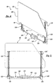
- a window lift system 90 for raising and lowering a window glass 92 as a useful example for understanding the invention is shown in Figure 4.
- the window lift system 90 generally comprises a forward support 94 and rearward support 96 engaging a bottom edge 98 of the window glass 92.
- the forward and rearward supports 94, 96 are positioned adjacent forward and rearward edges 100, 102, respectively, of the window glass 92.
- Each of the supports 94, 96 is threadably engaged by a threaded shaft 106, 108 respectively.
- the threaded shafts 106, 108 or screws, are rotatably mounted to a door trim panel 110. Rotation of the threaded shafts 106, 108 causes raising or lowering of the supports 94, 96 and window glass 92.
- a single motor 114 drives both threaded shafts 106, 108.
- the motor 114 is preferably mounted adjacent a lower edge of the door trim panel 110.
- the motor 114 rotatably drives a pair of rotary cables 116 extending from either axial end of the motor 114.
- the cables 116 are mounted in conduit 118.
- each of the cables 116 rotatably drives a spur gear 120 which engages a face gear 122 mounted at a lower end of each threaded shaft 106, 108.
- the motor 114 rotatably drives cables 116 and spur gears 120.
- Spur gears 120 rotatably drive face gears 122 and therefore threaded shafts 106, 108. Rotation of threaded shafts 106, 108 causes the raising and lowering of supports 94, 96 and therefore window glass 92.
- the drive mechanisms i.e. the threaded shafts 106, 108 and supports 94, 96
- the threaded shafts 106, 108 and supports 94, 96 are positioned adjacent the forward edge 100 and rearward edge 102 of the window glass 92, they will also be positioned close to the A and B pillars in the door.
- the threaded shafts 106, 108 could be replaced with other linear displacement devices, such as belt drive systems.
- the window lift system 90 preferably utilizes a single motor 114 in order to reduce costs, more than one motor could also be used.
- the motor 48 includes a gear unit which selectively provides one of a plurality of gear ratios, such that the speed of the armature shaft can be reduced and torque can be increased.
Abstract
Description
Claims (7)
- A window lift system (20) including a motor (48) rotatably driving a threaded shaft (50), an arm (24) having a first (26) and second (28) end used to raise/lower a window glass (22), the first end (26) supporting the window glass (22), and a threaded slide (52) threadably engaging said shaft (50);
the system characterised by a link (54) having a first end (56) pivotally mounted to said slide and an opposite second end (58) pivotally mounted to said second end (28) of said arm (24), said slide (52) engaging said second end (28) of said arm (24) through said link (54), such that rotation of said shaft (50) causes linear displacement of said slide (52) relative to said shaft (50) and therefore pivotal movement of said arm (24) through said link (54) about a fixed pivot point (30) located between said first (26) and second (28) ends. - The window lift system (20) of Claim 1 wherein said slide (52) comprises an internally threaded nut.
- The window lift system (20) of Claim 1 further comprising a bracket (46), said bracket (46) defining a guide (66) limiting movement of said slide (52) along said guide (66).
- The window lift system (20) of Claim 3 wherein said guide (66) is a slot in said bracket (46), said slide (52) including a portion extending into said slot.
- The window lift system (20) of Claim 4 wherein said arm (24) is pivotally mounted to said bracket (46) and said motor (48) is mounted to said bracket (46).
- The window lift system (20) of Claim 1 wherein said arm (24) is a first arm, said window lift system (24) including a second arm (34) having a first end (38) for supporting a window glass (22) and a slidably mounted opposite second end (40).
- The window lift system (20) of Claim 1 further including a gear unit (51) coupling said motor (48) to said threaded shaft (50), said gear unit (51) providing a plurality of gear ratios between said motor (48) and said threaded shaft (50).
Applications Claiming Priority (3)
| Application Number | Priority Date | Filing Date | Title |
|---|---|---|---|
| US890189 | 1997-07-09 | ||
| US08/890,189 US6003268A (en) | 1997-07-09 | 1997-07-09 | Window lift system |
| PCT/US1998/013746 WO1999002811A1 (en) | 1997-07-09 | 1998-07-01 | Window lift system |
Publications (2)
| Publication Number | Publication Date |
|---|---|
| EP1009900A1 EP1009900A1 (en) | 2000-06-21 |
| EP1009900B1 true EP1009900B1 (en) | 2004-12-01 |
Family
ID=25396367
Family Applications (1)
| Application Number | Title | Priority Date | Filing Date |
|---|---|---|---|
| EP98933075A Expired - Lifetime EP1009900B1 (en) | 1997-07-09 | 1998-07-01 | Window lift system |
Country Status (7)
| Country | Link |
|---|---|
| US (1) | US6003268A (en) |
| EP (1) | EP1009900B1 (en) |
| JP (1) | JP2002509592A (en) |
| AT (1) | ATE283960T1 (en) |
| CA (1) | CA2290691A1 (en) |
| DE (1) | DE69827953T2 (en) |
| WO (1) | WO1999002811A1 (en) |
Families Citing this family (7)
| Publication number | Priority date | Publication date | Assignee | Title |
|---|---|---|---|---|
| GB2351122B (en) * | 1999-06-14 | 2003-11-26 | Colin George Harper | Articulated window screen for executive boxes |
| US6866322B2 (en) | 2003-02-06 | 2005-03-15 | Asc Incorporated | Automotive vehicle roof system having a detachable convertible roof |
| US6811059B2 (en) * | 2003-02-24 | 2004-11-02 | Sealed Air Corporation (Us) | Self-cleaning fluid dispenser |
| JP2011058215A (en) * | 2009-09-08 | 2011-03-24 | Shiroki Corp | Regulator device of vehicle door glass |
| JP5743504B2 (en) * | 2010-11-30 | 2015-07-01 | シロキ工業株式会社 | Window regulator |
| US20120223540A1 (en) * | 2011-03-01 | 2012-09-06 | L&W Engineering, Inc. | Recreational Vehicle Lift Mechanism |
| DE102016200019A1 (en) * | 2016-01-05 | 2017-07-06 | Stabilus Gmbh | scissor drive |
Family Cites Families (18)
| Publication number | Priority date | Publication date | Assignee | Title |
|---|---|---|---|---|
| US1654747A (en) * | 1922-01-16 | 1928-01-03 | Dura Co | Window-control mechanism |
| US2115632A (en) * | 1937-09-13 | 1938-04-26 | John H Hanley | Device for raising and lowering automobile window glass |
| US2336530A (en) * | 1941-05-05 | 1943-12-14 | Aresee Company Inc | Floating drive mechanism for automobile door windows |
| US2337902A (en) * | 1941-09-11 | 1943-12-28 | Ternstedt Mfg Co | Power operated window regulator |
| US2640694A (en) * | 1950-08-04 | 1953-06-02 | Chrysler Corp | Window regulator |
| DE1208215B (en) * | 1953-11-13 | 1965-12-30 | Anderson Co | Device for raising and lowering a window sash or the like. |
| US2710058A (en) * | 1954-06-01 | 1955-06-07 | Theodore H Gronlund | Vehicle window and screen |
| US2883780A (en) * | 1957-08-27 | 1959-04-28 | Goodman Morris | Parking station |
| GB944860A (en) * | 1961-09-19 | 1963-12-18 | Wilmot Breeden Ltd | Improvements in or relating to window regulators |
| DE2739633A1 (en) * | 1977-09-02 | 1979-03-08 | Brose & Co Metallwerk Max | DEVICE FOR LIFTING AND LOWERING A DISC, IN PARTICULAR FOR MOTOR VEHICLES |
| US4119341A (en) * | 1977-12-08 | 1978-10-10 | Cook Eddie G | Rear window assembly for a truck cab |
| US4170847A (en) * | 1978-06-01 | 1979-10-16 | Ferro Manufacturing Corporation | Tailgate window regulator |
| US4235117A (en) * | 1978-12-07 | 1980-11-25 | Ferro Manufacturing Corporation | Tailgate window regulator |
| FR2455667A1 (en) * | 1979-05-04 | 1980-11-28 | Paumellerie Electrique | WINDOW REGULATOR |
| US5015030A (en) * | 1989-04-07 | 1991-05-14 | General Motors Corporation | Drive linkage for automobile sunroof |
| US5101596A (en) * | 1991-04-18 | 1992-04-07 | General Motors Corporation | Downstop for window regulator |
| DE4123193A1 (en) * | 1991-07-12 | 1993-01-14 | Braren Cyclo Getriebe | Electric motor-driven window lifter with pivotable arm - has counterbalancing spring wound about pivot axis to reduce loading by wt. of arm and window |
| IT1259548B (en) * | 1992-04-17 | 1996-03-20 | Roltra Morse Spa | WINDOW REGULATOR FOR VEHICLES |
-
1997
- 1997-07-09 US US08/890,189 patent/US6003268A/en not_active Expired - Fee Related
-
1998
- 1998-07-01 JP JP50875899A patent/JP2002509592A/en active Pending
- 1998-07-01 AT AT98933075T patent/ATE283960T1/en not_active IP Right Cessation
- 1998-07-01 DE DE69827953T patent/DE69827953T2/en not_active Expired - Fee Related
- 1998-07-01 CA CA002290691A patent/CA2290691A1/en not_active Abandoned
- 1998-07-01 WO PCT/US1998/013746 patent/WO1999002811A1/en active IP Right Grant
- 1998-07-01 EP EP98933075A patent/EP1009900B1/en not_active Expired - Lifetime
Also Published As
| Publication number | Publication date |
|---|---|
| DE69827953D1 (en) | 2005-01-05 |
| ATE283960T1 (en) | 2004-12-15 |
| JP2002509592A (en) | 2002-03-26 |
| US6003268A (en) | 1999-12-21 |
| DE69827953T2 (en) | 2005-03-31 |
| WO1999002811A1 (en) | 1999-01-21 |
| EP1009900A1 (en) | 2000-06-21 |
| CA2290691A1 (en) | 1999-01-21 |
Similar Documents
| Publication | Publication Date | Title |
|---|---|---|
| US5012613A (en) | Power window apparatus | |
| US5806244A (en) | Single drive dual rack and pinion window regulator | |
| US7347480B2 (en) | Electromotive sunvisor assembly of a vehicle and the method thereof | |
| US5657580A (en) | Window regulator with spring actuated direct cable tensioning | |
| KR20010108476A (en) | An extendable and pivotal rearview mirror assembly | |
| EP1009900B1 (en) | Window lift system | |
| CA2411039C (en) | Power sliding cab window | |
| EP2567843A3 (en) | Vehicle sunroof assembly | |
| US20030110700A1 (en) | Plug door drive system | |
| JPH0423715B2 (en) | ||
| US5537781A (en) | Hard-top vehicle window regulator system | |
| US2899832A (en) | Window regulator drive mechanism | |
| US5210900A (en) | Rotary window cleaner | |
| US4716681A (en) | Window regulator for an automotive vehicle | |
| JP3095356B2 (en) | Display opening / closing structure | |
| CN210343071U (en) | Automobile side sliding door driving mechanism | |
| JPH10119662A (en) | Opening/closing structure of display | |
| US20060075685A1 (en) | Displacement mechanism | |
| EP0007851A1 (en) | Drive arrangement for a sliding panel of an automobile, in particular a door's pane raiser | |
| US20230116133A1 (en) | Opening/closing device for vehicle sliding-window panel | |
| JPS5911929A (en) | Seat lifter | |
| JP3100344B2 (en) | Display opening / closing structure | |
| CN219451857U (en) | Bevel gear driving mechanism for automobile door | |
| JPH0743663U (en) | Power window equipment | |
| CA2417291A1 (en) | Dual arm window regulator drive system |
Legal Events
| Date | Code | Title | Description |
|---|---|---|---|
| PUAI | Public reference made under article 153(3) epc to a published international application that has entered the european phase |
Free format text: ORIGINAL CODE: 0009012 |
|
| 17P | Request for examination filed |
Effective date: 19991204 |
|
| AK | Designated contracting states |
Kind code of ref document: A1 Designated state(s): AT BE DE ES FR GB IT |
|
| 17Q | First examination report despatched |
Effective date: 20010427 |
|
| GRAP | Despatch of communication of intention to grant a patent |
Free format text: ORIGINAL CODE: EPIDOSNIGR1 |
|
| GRAS | Grant fee paid |
Free format text: ORIGINAL CODE: EPIDOSNIGR3 |
|
| GRAA | (expected) grant |
Free format text: ORIGINAL CODE: 0009210 |
|
| AK | Designated contracting states |
Kind code of ref document: B1 Designated state(s): AT BE DE ES FR GB IT |
|
| PG25 | Lapsed in a contracting state [announced via postgrant information from national office to epo] |
Ref country code: IT Free format text: LAPSE BECAUSE OF FAILURE TO SUBMIT A TRANSLATION OF THE DESCRIPTION OR TO PAY THE FEE WITHIN THE PRESCRIBED TIME-LIMIT;WARNING: LAPSES OF ITALIAN PATENTS WITH EFFECTIVE DATE BEFORE 2007 MAY HAVE OCCURRED AT ANY TIME BEFORE 2007. THE CORRECT EFFECTIVE DATE MAY BE DIFFERENT FROM THE ONE RECORDED. Effective date: 20041201 Ref country code: FR Free format text: LAPSE BECAUSE OF NON-PAYMENT OF DUE FEES Effective date: 20041201 Ref country code: BE Free format text: LAPSE BECAUSE OF FAILURE TO SUBMIT A TRANSLATION OF THE DESCRIPTION OR TO PAY THE FEE WITHIN THE PRESCRIBED TIME-LIMIT Effective date: 20041201 Ref country code: AT Free format text: LAPSE BECAUSE OF FAILURE TO SUBMIT A TRANSLATION OF THE DESCRIPTION OR TO PAY THE FEE WITHIN THE PRESCRIBED TIME-LIMIT Effective date: 20041201 |
|
| REG | Reference to a national code |
Ref country code: GB Ref legal event code: FG4D |
|
| REF | Corresponds to: |
Ref document number: 69827953 Country of ref document: DE Date of ref document: 20050105 Kind code of ref document: P |
|
| PG25 | Lapsed in a contracting state [announced via postgrant information from national office to epo] |
Ref country code: ES Free format text: LAPSE BECAUSE OF FAILURE TO SUBMIT A TRANSLATION OF THE DESCRIPTION OR TO PAY THE FEE WITHIN THE PRESCRIBED TIME-LIMIT Effective date: 20050312 |
|
| PG25 | Lapsed in a contracting state [announced via postgrant information from national office to epo] |
Ref country code: GB Free format text: LAPSE BECAUSE OF NON-PAYMENT OF DUE FEES Effective date: 20050701 |
|
| PLBE | No opposition filed within time limit |
Free format text: ORIGINAL CODE: 0009261 |
|
| STAA | Information on the status of an ep patent application or granted ep patent |
Free format text: STATUS: NO OPPOSITION FILED WITHIN TIME LIMIT |
|
| 26N | No opposition filed |
Effective date: 20050902 |
|
| EN | Fr: translation not filed | ||
| PG25 | Lapsed in a contracting state [announced via postgrant information from national office to epo] |
Ref country code: DE Free format text: LAPSE BECAUSE OF NON-PAYMENT OF DUE FEES Effective date: 20060201 |
|
| GBPC | Gb: european patent ceased through non-payment of renewal fee |
Effective date: 20050701 |