EP1009877B9 - Method and apparatus for drying a coated paper web - Google Patents
Method and apparatus for drying a coated paper web Download PDFInfo
- Publication number
- EP1009877B9 EP1009877B9 EP98932189A EP98932189A EP1009877B9 EP 1009877 B9 EP1009877 B9 EP 1009877B9 EP 98932189 A EP98932189 A EP 98932189A EP 98932189 A EP98932189 A EP 98932189A EP 1009877 B9 EP1009877 B9 EP 1009877B9
- Authority
- EP
- European Patent Office
- Prior art keywords
- web
- nozzles
- overpressure
- turning device
- counterpart
- Prior art date
- Legal status (The legal status is an assumption and is not a legal conclusion. Google has not performed a legal analysis and makes no representation as to the accuracy of the status listed.)
- Expired - Lifetime
Links
Images

Classifications
-
- F—MECHANICAL ENGINEERING; LIGHTING; HEATING; WEAPONS; BLASTING
- F26—DRYING
- F26B—DRYING SOLID MATERIALS OR OBJECTS BY REMOVING LIQUID THEREFROM
- F26B13/00—Machines and apparatus for drying fabrics, fibres, yarns, or other materials in long lengths, with progressive movement
- F26B13/10—Arrangements for feeding, heating or supporting materials; Controlling movement, tension or position of materials
- F26B13/101—Supporting materials without tension, e.g. on or between foraminous belts
- F26B13/104—Supporting materials without tension, e.g. on or between foraminous belts supported by fluid jets only; Fluid blowing arrangements for flotation dryers, e.g. coanda nozzles
-
- D—TEXTILES; PAPER
- D21—PAPER-MAKING; PRODUCTION OF CELLULOSE
- D21F—PAPER-MAKING MACHINES; METHODS OF PRODUCING PAPER THEREON
- D21F5/00—Dryer section of machines for making continuous webs of paper
- D21F5/18—Drying webs by hot air
- D21F5/185—Supporting webs in hot air dryers
- D21F5/187—Supporting webs in hot air dryers by air jets
-
- D—TEXTILES; PAPER
- D21—PAPER-MAKING; PRODUCTION OF CELLULOSE
- D21H—PULP COMPOSITIONS; PREPARATION THEREOF NOT COVERED BY SUBCLASSES D21C OR D21D; IMPREGNATING OR COATING OF PAPER; TREATMENT OF FINISHED PAPER NOT COVERED BY CLASS B31 OR SUBCLASS D21G; PAPER NOT OTHERWISE PROVIDED FOR
- D21H25/00—After-treatment of paper not provided for in groups D21H17/00 - D21H23/00
- D21H25/04—Physical treatment, e.g. heating, irradiating
- D21H25/06—Physical treatment, e.g. heating, irradiating of impregnated or coated paper
Definitions
- the present invention relates to a method and an apparatus for drying a coated paper web.
- a static underpressure zone is formed between the nozzles and the web in the nozzle area in the said counterparts known per se, principally over the entire nozzle area.
- the aim is to use this underpressure to intensify the pushing effect of the turning device by means of suction in the counterpart area. Suction is used to spread the web outwards in order to stabilize the web on its curved course.
- underpressure nozzles there is a risk that paper web, should it slacken for example due to tension variations, contacts the nozzles of the counterpart whereupon the coating is damaged and/or the web breaks.
- Patent publication US 3,549,070 shows an arrangement for use in web offset printing or also for heavy boards and even to steel plates. The use of sine wave is mentioned as a solution for light paper webs.
- Patent publication EP 770 731 shows an arrangement in drying a paper web in a straight dryer and by using a turning device prior to that portion. Nozzles in the turning device are situated on one side of the path.
- the object of the present invention is thus to provide a new, improved method and an apparatus in which the drawbacks presented above have been minimized.
- a further object is to provide a method and an apparatus providing a larger drying capacity of the paper web than before, and thus save space in the machine room.
- Overpressure nozzles refer hereto nozzles the blows of which generate a web pushing power at all distances from the web.
- the starting point has been the reverse; in them, underpressure nozzles have been used for generating at a certain distance from the web a power opposite to the pushing power in order to spread the web.
- the overpressure nozzles of the invention it is possible to control the running of the web better and to ensure that the web stays apart from the nozzles.
- the counterpart may be provided with, for example, Float or Push nozzles disclosed in the applicant's US patent 4384666.
- the counterpart may also be provided with simple impingement nozzles which include, for example, a perforated plate or one or more slots extending across the web, from which air is blown principally directly against the web.
- the overpressure nozzles of the counterpart are arranged radially against the blow nozzles of the turning device, i.e. so that blows from the counterpart are directed against the paper web and against the blows from the turning device arranged on the first side of the web.
- the blows for example from Float overpressure nozzles, generate a local overpressure on both sides of the web between the paper web and the carrier surfaces of the nozzle, i.e. the nozzle surfaces; with this overpressure, the running of the paper web may be stabilized and the runnability and controllability of the web may be improved.
- Impingement nozzles provide the same result, although the pressure generated by the impingement nozzles generally is slightly lower than the pressure generated by overpressure nozzles of the Float type.
- floating nozzles on the opposite sides of the paper web are, however, arranged advantageously interlaced with each other so that the web travels in a sine-wave path between the nozzles arranged on both sides of the web, which allows an as smooth as possible web run.
- the running direction of the web may be turned even 20°-260°, typically 30°-160°.
- the actual turning device of the invention in which the running direction of the paper web may be turned 20°-260°, comprises typically 3-15 blow nozzles.
- the counterpart comprises the same number of overpressure nozzles, i.e. 3-15 nozzles.
- the blow nozzles of the actual turning device are overpressure nozzles.
- the pushing nozzles of both the turning device and the counterpart are principally so-called Float overpressure nozzles of the applicant.
- the nozzles in the turning section additionally are arranged opposite to each other on both sides of the web, the pushing forces caused by the nozzle flows are directed against each other. This generates a local overpressure at the carrier surface areas of the nozzles on both sides of the web.
- the local overpressures arranged opposite to each other on both sides of the web have a stabilizing effect on the web run, and improve the runnability and controllability of the web, also in cases of disturbance.
- the arrangement of the invention provides an optimal configuration of nozzles as to the control of the web.
- overpressure nozzles such as Float nozzles
- underpressure nozzles known per se such as Foil or Pull nozzles disclosed in the applicant's patent US 4247993
- the important advantage is achieved compared with the known technology, that it is considerably less probable that, due to tension variations, the paper web would contact the nozzles of the counterpart or the turning device, because the overpressure nozzle pushes the web away, while an underpressure nozzle is not necessarily always able to keep the web away from the nozzle surface.
- the turning device of the invention is further advantageously provided with a control device, increasing the controllability of the turning device and making it possible to automatically control the distance between the turning device and the web, this control being based on the ratio between the supply air pressure of the turning device and the pad pressure.
- the pressures may be used for automatically calculating the tension of the web.
- control device typically comprises
- the pad pressure refers to overpressure in the turning device, generated into the turning device, as a box or a similar structure arranged around it restricts the discharge of blowing air from the turning device. With a certain turning device structure, the pad pressure is principally dependent on the amount of air led to the turning device, the pressure prevailing in the counterpart, and the tension of the web. The pad pressure is measured in the free space between the nozzles of the turning device.
- the distance between the carrier surface of the nozzles and the paper web is generally controlled either by adjusting the operating speed of the blower blowing air to the blow nozzles of the turning device, or by a guide vane adjuster so that, by controlling the air supply in this way, also the nozzle pressure P SP of the blow nozzles, and thus also the distance of the web from the nozzles, is controlled.
- the automatic adjustment of the distance between the carrier surface of the turning device nozzles and the paper web is in practice carried out so that the internal pressure P SP of the nozzle of the turning device and the pad pressure P KL between the paper web and the turning device are measured automatically by two pressure sensors, whereafter the distance of the web from the nozzle surface is automatically calculated with the help of the ratio between the internal pressure in the nozzle (nozzle pressure) and the pad pressure, using the above mentioned formula.
- this ratio may be corrected by adjusting the supply of blowing air so that the distance of the web from the nozzle surface remains at a desired level.
- the adjustment may be automatic, in which case the aim is usually to maintain the distance constant by keeping the ratio between the nozzle pressure and pad pressure constant.
- the web run may thus be corrected with the said pressure adjustment, for example, in a case in which the paper web is drawn away from the nozzle surface due to the decrease in web tension.
- the pad pressure of the turning device decreases and the ratio between the nozzle pressure P SP and the pad pressure P KL increases.
- the nozzle pressure may thus be automatically reduced whereupon the ratio of the nozzle pressure and the pad pressure, and thus also the distance of the web from the nozzle surface, decreases.
- the calculated tension value may be used for controlling the tension adjustment.
- a static pressure P VK deviating from the atmospheric pressure may be generated between the web and the counterpart, which is dependent on the running mode, and on the supply and discharge of air; this pressure may be above or below the atmospheric pressure, in which case it has to be taken into account when calculating the tension. It may be mentioned that the pressures given in this application generally refer to pressures in relation to the atmospheric pressure, unless stated otherwise.
- the pressure in the counterpart also affects the pad pressure between the turning device and the web.
- the pressure in the counterpart may thus also be controlled from the counterpart side.
- the overpressure nozzles of the counterpart, as well as the blow nozzles of the turning device may be used for blowing hot air onto the paper web, the temperature of air being 100-450°C, preferably 150-400°C, and the speed of air 20-100 m/s, preferably 40-80 m/s so that the paper web may efficiently be dried from both sides of the web already in the turning section.
- the overpressure nozzles may be used for blowing hot air onto the paper web, the temperature of air being 100-450°C, preferably 150-400°C, and the speed of air 20-100 m/s, preferably 40-80 m/s so that the paper web may efficiently be dried from both sides of the web already in the turning section.
- a more efficient drying is achieved by overpressure nozzles than by underpressure nozzles, due to better nozzle geometry.
- With the overpressure nozzles a bigger heat transmission coefficient may be achieved than with underpressure nozzles, due e.g. to the turbulence of the air flow being discharge
- the turning device on the first side of the paper web and the airborne web-dryer unit following it may advantageously be covered with a common housing structure.
- the counterpart on the opposite side of the web and the airborne web-dryer unit following it may advantageously be covered with a common housing structure.
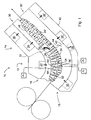
- Fig. 1 shows a two-sided turning device 10 in accordance with the invention for drying a coated paper web W.
- the device comprises a device 12 turning the running direction of the paper web, and a drying apparatus 14 arranged in the running direction of the web after the web turning device.
- the turning device comprises the actual turning device 16 on the first side of the web, in the case shown in the Figure above the web, and a counterpart 18 for this device on the second side of the web.
- the turning device 16 comprises six blow nozzles 20 which, in the case of the Figure, are overpressure nozzles of the so-called Float type of the applicant.
- the Float nozzles are symmetrical nozzles, from the longitudinal slots on both edges transverse to the web of the carrier surface of which blows are directed against each other and against the web, forming an overpressure zone between the nozzle and the web, and turning the running direction of the web about 70-80 degrees, in the case shown in the Figure.
- the turning device 16 of the Figure has its own air system with air supply channels 22 for bringing make-up air to the turning device.
- air in the machine room, exhaust air from the airborne web-dryer, circulating air, or a mixture of these, for example, may be used as blowing air.
- the counterpart 18 has likewise six overpressure nozzles 24 arranged on the second side of the web exactly opposite to the nozzles 20 of the turning device.
- the counterpart may have an air supply system of its own with air supply channels 26, as is shown in broken lines in Fig. 1.
- the counterpart may also have its own exhaust or return air system with exhaust air channels 28, into which air blown against the web is absorbed, as is also shown in broken lines in Fig. 1.
- the supply and discharge of air in the counterpart may advantageously be arranged through the drying apparatus, as is explained below.
- the drying apparatus 14 is an airborne web-dryer with separate airborne web-dryers or airborne web-dryer units 30 and 30' on both sides of the web.
- the upper airborne web-dryer unit 30 is combined with the turning device 16 under the same housing structure 32. However, the turning device is separated from the airborne web-dryer unit by a partition 39.
- the said airborne web-dryer unit 30 above the web has its own air supply system with air supply channels 34.
- the airborne web-dryer unit 30 also has its own exhaust air system with exhaust air channels 36. From the turning device 16, air is transferred along with the web to the upper airborne web-dryer unit, as is in an exemplary way shown with arrow 38, and from there onwards into the exhaust air channel 36. The necessary amount of make-up air is brought to the turning device.
- the lower airborne web-dryer unit 30' is connected in a similar way to the counterpart 18 with a common housing structure 40. Exhaust air from the counterpart is arranged to flow into the exhaust air channel 36' of the airborne web-dryer unit 30'. Supply air, i.e. pressurized blowing air is led to the counterpart through the air supply channel 34' of the airborne web-dryer unit 30'.
- the supply air systems for the airborne web-dryer 30' and the counterpart 18, as well as the exhaust air systems may be separated from each other by a partition 42 restricting the flow, which is provided with an adjustable damper 44 or a similar element, as is shown in broken lines in Fig. 1, with which the supply of air of the counterpart may be adjusted separately from the air flows of the airborne web-dryer unit.
- the floating or blow nozzles 46 and 46' are interlaced so that the web runs in a sine-wave form through the straight airborne web-dryer section.
- Fig. 1 also indicates the pressure measurements for the control system of the turning device.
- the pressure sensor 48 arranged into the blow nozzle 20 of the actual turning device 16 measures the nozzle pressure P SP of the nozzle.
- the pressure sensor 50 arranged between the nozzles 20 of the turning device measures the pad pressure P KL of the turning device.
- the pressure sensor 56 arranged between the nozzles 24 of the counterpart may respectively be used for measuring the possible underpressure or overpressure P VK in the counterpart.
- the small arrows indicate how the blows from the nozzles 20 and 24 arranged on both sides of the web blow against each other, forming a local overpressure between the nozzle carrier surfaces 52 and 54 and the paper web on both sides of the web. These local overpressures have a stabilizing effect on the paper web and improve the runnability and controllability of the web.
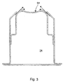
- Fig. 3 shows an enlargement of an overpressure nozzle 24 of the US patent 4,384,666 used in a counterpart of the invention.
- the arrows indicate the direction of the blows from the carrier surface 54 towards the web.
- Fig. 2 The control system for a two-sided turning device in accordance with the invention is shown in more detail in Fig. 2. It may be seen from Fig. 2, that the measuring results from the differential pressure instruments 48 and 50 are led to the control device 58 with which it is possible to control the blower 60 feeding air into the air supply channel 22 of the turning device 16.
- FIG. 2 shows the alternative in which both the supply air and the exhaust air arrangement of the counterpart are connected to the airborne web-dryer unit 30'.
Landscapes
- Engineering & Computer Science (AREA)
- Textile Engineering (AREA)
- Mechanical Engineering (AREA)
- General Engineering & Computer Science (AREA)
- Paper (AREA)
- Drying Of Solid Materials (AREA)
- Organic Low-Molecular-Weight Compounds And Preparation Thereof (AREA)
- Preparation Of Compounds By Using Micro-Organisms (AREA)
Applications Claiming Priority (3)
| Application Number | Priority Date | Filing Date | Title |
|---|---|---|---|
| FI972878A FI114933B (sv) | 1997-07-07 | 1997-07-07 | Förfarande och anordning för torkning av bestruken pappersbana eller motsvarande |
| FI972878 | 1997-07-07 | ||
| PCT/FI1998/000567 WO1999002773A1 (en) | 1997-07-07 | 1998-07-03 | Method and apparatus for drying a coated paper web or the like |
Publications (3)
| Publication Number | Publication Date |
|---|---|
| EP1009877A1 EP1009877A1 (en) | 2000-06-21 |
| EP1009877B1 EP1009877B1 (en) | 2006-05-10 |
| EP1009877B9 true EP1009877B9 (en) | 2006-12-13 |
Family
ID=8549203
Family Applications (1)
| Application Number | Title | Priority Date | Filing Date |
|---|---|---|---|
| EP98932189A Expired - Lifetime EP1009877B9 (en) | 1997-07-07 | 1998-07-03 | Method and apparatus for drying a coated paper web |
Country Status (10)
| Country | Link |
|---|---|
| US (1) | US6293031B1 (sv) |
| EP (1) | EP1009877B9 (sv) |
| JP (1) | JP3488689B2 (sv) |
| AT (1) | ATE325924T1 (sv) |
| AU (1) | AU8217798A (sv) |
| CA (1) | CA2294862C (sv) |
| DE (2) | DE1009877T1 (sv) |
| ES (1) | ES2262235T3 (sv) |
| FI (1) | FI114933B (sv) |
| WO (1) | WO1999002773A1 (sv) |
Families Citing this family (8)
| Publication number | Priority date | Publication date | Assignee | Title |
|---|---|---|---|---|
| US6634120B2 (en) | 2001-03-26 | 2003-10-21 | Voith Paper Patent Gmbh | Apparatus for coating moving fiber webs |
| DE60129409T2 (de) * | 2001-03-26 | 2008-04-03 | Voith Patent Gmbh | Vorrichtung zur Beschichtung einer laufenden Bahn, insbesondere einer Papier- oder Kartonbahn |
| US6851367B2 (en) * | 2002-08-08 | 2005-02-08 | Presstek, Inc. | Web handling cylinder with modulated tension loss |
| US7118062B2 (en) * | 2002-08-08 | 2006-10-10 | Presstek, Inc. | Web handling with tension sensing and adjustment |
| US7828547B2 (en) * | 2004-12-10 | 2010-11-09 | Kodak Graphic Communications | Method and apparatus for rapidly heating printing plates |
| FI120368B (sv) | 2007-10-25 | 2009-09-30 | Metso Paper Inc | Förfarande och arrangemang för att reglera egenskaperna hos en fiberbana |
| US8088255B2 (en) | 2008-04-18 | 2012-01-03 | Honeywell Asca Inc | Sheet stabilizer with dual inline machine direction air clamps and backsteps |
| FI20085539A0 (sv) * | 2008-06-03 | 2008-06-03 | Upm Kymmene Oyj | Anordning och förfarande för torkning av en bana |
Family Cites Families (8)
| Publication number | Priority date | Publication date | Assignee | Title |
|---|---|---|---|---|
| US3549070A (en) * | 1969-02-27 | 1970-12-22 | Tec Systems | Floatation of sheet materials |
| US4848633A (en) * | 1986-02-28 | 1989-07-18 | Thermo Electron Web Systems, Inc. | Non-contact web turning and drying apparatus |
| US4833794A (en) * | 1988-08-10 | 1989-05-30 | Advance Systems, Inc. | Dryer apparatus for floating a running web and having baffle means for spent return air |
| DE4110875A1 (de) | 1991-04-04 | 1992-10-08 | Voith Gmbh J M | Trockenpartie |
| IT1253394B (it) * | 1991-10-18 | 1995-08-08 | Dispositivo per asciugare con aria calda un film stampato in una macchina rotocalco. | |
| FR2710971B1 (fr) * | 1993-10-06 | 1995-12-29 | Infra Rouge System | Dispositif de déviation sans contact pour matériau en feuille. |
| US5634402A (en) * | 1995-10-12 | 1997-06-03 | Research, Incorporated | Coating heater system |
| FI98944C (sv) * | 1995-10-25 | 1997-09-10 | Valmet Corp | Förfarande och anordning vid torkning av beläggningen av en pappersbana eller motsvarande |
-
1997
- 1997-07-07 FI FI972878A patent/FI114933B/sv not_active IP Right Cessation
-
1998
- 1998-07-03 WO PCT/FI1998/000567 patent/WO1999002773A1/en active IP Right Grant
- 1998-07-03 JP JP2000502258A patent/JP3488689B2/ja not_active Expired - Fee Related
- 1998-07-03 AT AT98932189T patent/ATE325924T1/de active
- 1998-07-03 CA CA002294862A patent/CA2294862C/en not_active Expired - Lifetime
- 1998-07-03 AU AU82177/98A patent/AU8217798A/en not_active Abandoned
- 1998-07-03 DE DE1009877T patent/DE1009877T1/de active Pending
- 1998-07-03 EP EP98932189A patent/EP1009877B9/en not_active Expired - Lifetime
- 1998-07-03 US US09/462,293 patent/US6293031B1/en not_active Expired - Lifetime
- 1998-07-03 ES ES98932189T patent/ES2262235T3/es not_active Expired - Lifetime
- 1998-07-03 DE DE69834496T patent/DE69834496T2/de not_active Expired - Lifetime
Also Published As
| Publication number | Publication date |
|---|---|
| DE69834496D1 (de) | 2006-06-14 |
| EP1009877A1 (en) | 2000-06-21 |
| AU8217798A (en) | 1999-02-08 |
| DE1009877T1 (de) | 2001-01-11 |
| JP2001509556A (ja) | 2001-07-24 |
| FI972878A0 (fi) | 1997-07-07 |
| EP1009877B1 (en) | 2006-05-10 |
| DE69834496T2 (de) | 2007-02-01 |
| ES2262235T3 (es) | 2006-11-16 |
| FI114933B (sv) | 2005-01-31 |
| CA2294862C (en) | 2006-10-31 |
| WO1999002773A1 (en) | 1999-01-21 |
| JP3488689B2 (ja) | 2004-01-19 |
| CA2294862A1 (en) | 1999-01-21 |
| ATE325924T1 (de) | 2006-06-15 |
| FI972878A (sv) | 1999-01-08 |
| US6293031B1 (en) | 2001-09-25 |
Similar Documents
| Publication | Publication Date | Title |
|---|---|---|
| US5009016A (en) | Method for on-machine coating-drying of a paper web or the like | |
| US4881327A (en) | Dryer section | |
| US4936025A (en) | Combination infrared and airborne drying of a web | |
| FI62571C (fi) | Anordning vid flercylindertork i en pappersmaskin | |
| EP0561256B1 (en) | Method for contact-free air-drying of a material web and air dryer that makes use of the method | |
| CA1314392C (en) | Cross directional gloss controller | |
| FI75008B (fi) | Svaevtork och foerfarande foer effektivering av dess funktion. | |
| US4942674A (en) | Method in the drying of a paper web or equivalent | |
| EP1009877B9 (en) | Method and apparatus for drying a coated paper web | |
| WO1989002953A1 (en) | Arrangement of pressure nozzles for the treatment of webs | |
| JPH03137288A (ja) | コーター等の乾燥部における方法および装置 | |
| FI78525C (sv) | Infratork | |
| EP0796415B1 (en) | Combination air bar and hole bar flotation dryer | |
| US10401085B2 (en) | Air bar arrangement for drying tissue on a belt | |
| CA2365683C (en) | Method and apparatus for stabilizing the running of a web in a paper machine or a like | |
| EP1412579B1 (en) | Method and apparatus for blowing drying gas in a paper machine | |
| JPS636192A (ja) | ノズルおよび紙乾燥設備 | |
| US20050223593A1 (en) | Step air foil | |
| JP2804810B2 (ja) | ウェブの支持転向延展装置 | |
| FI82848B (fi) | Foerfarande foer kontaktfri torkning av en pappers- eller kartongbana. | |
| JPS61266693A (ja) | 高速紙乾燥機用真空移送装置 | |
| JP2001335205A (ja) | 両面フロータ式乾燥機,両面フロータ式冷却機及び両面フロータ式加湿機 | |
| US8615899B2 (en) | Paired air bar/hole bar arrangement in web dryer | |
| FI75009C (sv) | Förfarande och anordning för kontaktlös torkning av en pappersbana ell er motsvarande | |
| FI82731B (fi) | Torkningsgrupp foer maongcylindertorken i en pappersmaskin. |
Legal Events
| Date | Code | Title | Description |
|---|---|---|---|
| PUAI | Public reference made under article 153(3) epc to a published international application that has entered the european phase |
Free format text: ORIGINAL CODE: 0009012 |
|
| 17P | Request for examination filed |
Effective date: 20000103 |
|
| AK | Designated contracting states |
Kind code of ref document: A1 Designated state(s): AT DE ES FR GB IT SE |
|
| DET | De: translation of patent claims | ||
| RAP1 | Party data changed (applicant data changed or rights of an application transferred) |
Owner name: METSO PAPER, INC. |
|
| 17Q | First examination report despatched |
Effective date: 20020304 |
|
| GRAP | Despatch of communication of intention to grant a patent |
Free format text: ORIGINAL CODE: EPIDOSNIGR1 |
|
| RTI1 | Title (correction) |
Free format text: METHOD AND APPARATUS FOR DRYING A COATED PAPER WEB |
|
| GRAS | Grant fee paid |
Free format text: ORIGINAL CODE: EPIDOSNIGR3 |
|
| GRAA | (expected) grant |
Free format text: ORIGINAL CODE: 0009210 |
|
| RIN1 | Information on inventor provided before grant (corrected) |
Inventor name: SOLIN, RICHARD Inventor name: RINGBOM, KNUT |
|
| AK | Designated contracting states |
Kind code of ref document: B1 Designated state(s): AT DE ES FR GB IT SE |
|
| REG | Reference to a national code |
Ref country code: GB Ref legal event code: FG4D |
|
| REF | Corresponds to: |
Ref document number: 69834496 Country of ref document: DE Date of ref document: 20060614 Kind code of ref document: P |
|
| REG | Reference to a national code |
Ref country code: SE Ref legal event code: TRGR |
|
| REG | Reference to a national code |
Ref country code: ES Ref legal event code: FG2A Ref document number: 2262235 Country of ref document: ES Kind code of ref document: T3 |
|
| ET | Fr: translation filed | ||
| PLBE | No opposition filed within time limit |
Free format text: ORIGINAL CODE: 0009261 |
|
| STAA | Information on the status of an ep patent application or granted ep patent |
Free format text: STATUS: NO OPPOSITION FILED WITHIN TIME LIMIT |
|
| 26N | No opposition filed |
Effective date: 20070213 |
|
| PGFP | Annual fee paid to national office [announced via postgrant information from national office to epo] |
Ref country code: SE Payment date: 20120725 Year of fee payment: 15 |
|
| PGFP | Annual fee paid to national office [announced via postgrant information from national office to epo] |
Ref country code: IT Payment date: 20120724 Year of fee payment: 15 |
|
| REG | Reference to a national code |
Ref country code: SE Ref legal event code: EUG |
|
| PG25 | Lapsed in a contracting state [announced via postgrant information from national office to epo] |
Ref country code: SE Free format text: LAPSE BECAUSE OF NON-PAYMENT OF DUE FEES Effective date: 20130704 |
|
| PG25 | Lapsed in a contracting state [announced via postgrant information from national office to epo] |
Ref country code: IT Free format text: LAPSE BECAUSE OF NON-PAYMENT OF DUE FEES Effective date: 20130703 |
|
| PGFP | Annual fee paid to national office [announced via postgrant information from national office to epo] |
Ref country code: FR Payment date: 20140721 Year of fee payment: 17 Ref country code: ES Payment date: 20140728 Year of fee payment: 17 |
|
| REG | Reference to a national code |
Ref country code: FR Ref legal event code: ST Effective date: 20160331 |
|
| PG25 | Lapsed in a contracting state [announced via postgrant information from national office to epo] |
Ref country code: FR Free format text: LAPSE BECAUSE OF NON-PAYMENT OF DUE FEES Effective date: 20150731 |
|
| REG | Reference to a national code |
Ref country code: ES Ref legal event code: FD2A Effective date: 20160829 |
|
| PG25 | Lapsed in a contracting state [announced via postgrant information from national office to epo] |
Ref country code: ES Free format text: LAPSE BECAUSE OF NON-PAYMENT OF DUE FEES Effective date: 20150704 |
|
| PGFP | Annual fee paid to national office [announced via postgrant information from national office to epo] |
Ref country code: DE Payment date: 20170724 Year of fee payment: 20 Ref country code: GB Payment date: 20170719 Year of fee payment: 20 |
|
| PGFP | Annual fee paid to national office [announced via postgrant information from national office to epo] |
Ref country code: AT Payment date: 20170720 Year of fee payment: 20 |
|
| REG | Reference to a national code |
Ref country code: DE Ref legal event code: R071 Ref document number: 69834496 Country of ref document: DE |
|
| REG | Reference to a national code |
Ref country code: GB Ref legal event code: PE20 Expiry date: 20180702 |
|
| REG | Reference to a national code |
Ref country code: AT Ref legal event code: MK07 Ref document number: 325924 Country of ref document: AT Kind code of ref document: T Effective date: 20180703 |
|
| PG25 | Lapsed in a contracting state [announced via postgrant information from national office to epo] |
Ref country code: GB Free format text: LAPSE BECAUSE OF EXPIRATION OF PROTECTION Effective date: 20180702 |