EP1009635B1 - Method and device for driving a printing press with an integrated imaging device - Google Patents
Method and device for driving a printing press with an integrated imaging device Download PDFInfo
- Publication number
- EP1009635B1 EP1009635B1 EP98936101A EP98936101A EP1009635B1 EP 1009635 B1 EP1009635 B1 EP 1009635B1 EP 98936101 A EP98936101 A EP 98936101A EP 98936101 A EP98936101 A EP 98936101A EP 1009635 B1 EP1009635 B1 EP 1009635B1
- Authority
- EP
- European Patent Office
- Prior art keywords
- printing
- drive
- cylinder
- forme cylinder
- driving
- Prior art date
- Legal status (The legal status is an assumption and is not a legal conclusion. Google has not performed a legal analysis and makes no representation as to the accuracy of the status listed.)
- Expired - Lifetime
Links
Images


Classifications
-
- B—PERFORMING OPERATIONS; TRANSPORTING
- B41—PRINTING; LINING MACHINES; TYPEWRITERS; STAMPS
- B41F—PRINTING MACHINES OR PRESSES
- B41F13/00—Common details of rotary presses or machines
- B41F13/008—Mechanical features of drives, e.g. gears, clutches
-
- B—PERFORMING OPERATIONS; TRANSPORTING
- B41—PRINTING; LINING MACHINES; TYPEWRITERS; STAMPS
- B41F—PRINTING MACHINES OR PRESSES
- B41F7/00—Rotary lithographic machines
- B41F7/02—Rotary lithographic machines for offset printing
- B41F7/10—Rotary lithographic machines for offset printing using one impression cylinder co-operating with several transfer cylinders for printing on sheets or webs, e.g. satellite-printing units
Definitions
- the invention relates to a method and a device for driving a printing press with at least one integrated imaging device.
- the elements mentioned are by a Gear train connected to each other. When imaging the printing form cylinder, this is Inking unit can be separated from the gear train.
- a disadvantage of this procedure is that the imaging takes a long time increases because the imaging speed, i.e. the speed at which the printing form cylinder rotated during imaging, identical to the maximum printing speed is
- EP 00 47 165 A1 is a rotary printing press with a laser beam imaging device known, which makes it possible to produce an image on a rotary printing form, while this is arranged on the form cylinder interacting with a printing cylinder.
- the laser beam imaging device, the impression cylinder and the forme cylinder are after a first variant connected to one another in terms of drive. According to a second variant these elements have individual drives that are synchronized by an electronic control system become.
- the object of the invention is to provide a method and a device which allows a high imaging speed and thus the time for imaging is minimized.
- the impression cylinder 1 is a sheet feeder consisting of a leading edge separator 4 and a pre-gripper system 6 for conveying a sheet to be printed from a stack of feeder sheets 5 and transfer to the printing cylinder 1 upstream.
- the feeding of the Bow to the impression cylinder 1 is such that only every second gripper row 3 of Printing cylinder is fed an arc.
- the printing cylinder 1 is a delivery chain circle 7 trained sheet removal assigned to the printed sheet from the impression cylinder 1 takes over and transported to the delivery sheet stack 8. Again, only everyone a second row of grippers 3 of the impression cylinder 1 a sheet is discharged.
- each cylinder group contains an offset cylinder 9 with two active surfaces which is operatively connected to the impression cylinder 1 and a printing form cylinder 10 with two active surfaces which is operatively connected to the offset cylinder 9.
- the cylinder - pressure cylinder 1; Offset cylinder 9 and printing form cylinder 10 are shown in the operating phase position, the effective surfaces with the start of printing 29 being opposite each other at the point of contact of the respective cylinder. In this operating phase position, the cylinders are connected to each other by the gear train.
- the pressure starts 29 of the cylinders - pressure cylinder 1 and offset cylinder 9 of the second cylinder group 18 - are shown in FIG. 1 as opposed to each other.
- An inking unit 19 is assigned to each active surface of each printing form cylinder 10.
- the inking unit 19 contains an application roller 20.
- the inking unit 19 is designed as an anilox inking unit.
- the anilox inking unit contains an ink metering roller 23, to which a doctor box 24 is assigned.
- the printing machine acc. Fig. 1 is with two cylinder groups 11; 18 equipped with two offset cylinders, each with two active surfaces, two printing form cylinders, each with two active surfaces and four inking units, and thus works as a four-color machine. If the printing machine is equipped with two offset cylinders, each with an effective area, two printing form cylinders, each with an effective area and 2 inking units, the printing machine works as a two-color machine.
- the printing press works as a one or two-color press.
- Fig. 2 is the drive wheel train of the printing press in the four-color version with two cylinder groups shown.
- the drive gear train includes a motor 12 with a motor pinion 13, an intermediate wheel 14, an impression cylinder drive wheel 15, two offset cylinder drive wheels 17, two printing form cylinder drive wheels 21, four form roller drive wheels 22 and four Ink metering drive wheels 25.
- the printing form cylinder is each assigned its own drive 26.
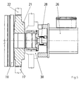
- the assignment of the self-drive 26 and the arrangement of the printing form cylinder drive wheel 21 on the printing form cylinder 10 is shown in FIG. 3.
- the printing form cylinder 10 is via a phase position coupling 27 assigned to the printing form cylinder drive wheel 21.
- the printing form cylinder drive wheel 21 is arranged in the gear train of the printing press and meshes with the offset cylinder drive wheel 17 and the application roller drive wheel 22.
- the printing form cylinder 10 is assigned to the self-propulsion 26 via a metal bellows coupling 28.
- the self-propulsion is designed as an electric motor.
- the method according to the invention is characterized in a printing press with a cylinder group 11 or 18 in that the drive connection (drive connection 4 - in the operating phase position) between the printing plate cylinder 10 and the printing plate cylinder drive wheel 21 is released by means of the phase position coupling 27 and thus the printing plate cylinder is quasi separated from the drive wheel train and the printing form cylinder 10 is driven by the self-drive 26 in the imaging phase.
- the rotational speed of the printing form cylinder 10 during imaging, ie the imaging speed is substantially above the maximum printing speed and is preferably 2-5 times the same. This ensures that the time for imaging is reduced to a minimum and the other machine parts are not stressed - the printing press is at a standstill.
- the printing form cylinder 10 is reintegrated into the drive wheel train in the operating phase position by means of the phase position coupling 27.
- Operating phase position means that the pressure starts 29 face the cylinders that are in operative connection and that printing operation is possible.
- a current for braking the printing press and for bracing the drive wheel train is applied to the self-drive 26 in printing operation.
- the existing self-propulsion is used to ensure tensioning of the drive wheel train in printing mode.
- the current supplied to the self-propulsion is preferably in the range of 10% of the current of the main drive motor 12. Since the current consumption of the main drive motor 12 is subject to fluctuations in printing operation, a current adapted to these fluctuations is supplied to the self-propelled drive.
- the drive connection between the printing forme cylinder drive wheel 21 and the drive wheel train is separated so that the printing forme cylinder can be separated from the drive wheel train and the printing form cylinder can be driven by the self-propelled in the imaging phase.
- the printing form cylinder 10 is reintegrated into the drive wheel train by rotating the eccentric bearing 30 in the operating phase position.
- Operating phase position means that the pressure starts of the cylinders in operative connection face each other and printing is possible.
- the drive connections (drive connections in the operating phase positions) between the printing form cylinders 10 and the printing form cylinder drive wheels 21 are released by means of the phase position couplings 27 and the printing form cylinders 10 are thus quasi separated from the drive wheel train.
- the printing form cylinders 10 are now driven by the self-drive 26 at an imaging speed.
- the overhaul mode which falls from the standstill to the imaging speed in the run-up phase of the self-propulsion, the printing form cylinders 10 are brought into an in-phase position relative to the imaging devices 16 from the respective operating phase positions.
- the in-phase position of the printing form cylinders 10 relative to the imaging devices 16 is preferably identical to the start of printing 29, ie that at the beginning of the imaging process both printing form cylinders 10 face the respective imaging device 16 with their printing starts.
- the printing form cylinders 10 are driven synchronously at the imaging speed.
- the printing form cylinders 10 are brought back into their respective operating phase positions. This is done as described below:
- the operating phase position of the respective printing form cylinder is overrun by the internal drive 26, i.e. the internal drive is stopped after passing the operating phase position, then the printing form cylinder is incorporated into the drive wheel train and mechanical means (phase coupling) take over the exact starting of the operating phase position when the drive wheel train is started up.
- the operating phase is started with the following process steps: The self-propulsion of the printing form cylinder is stopped before reaching the operating phase position, then the printing form cylinder is integrated into the drive wheel train and mechanical means (phase coupling) take over the exact starting of the operating phase position when the self-propulsion is started. Thereafter, according to a further development of the drive, at least one self-drive in the manner described is supplied with a current for braking the printing press and bracing the drive wheel train.
- the self-drive arranged on the printing form cylinder is also used in part or in total for driving the printing press in printing operation. This configuration is shown in FIGS. 6 and 7 and is described below using the drive scheme of the printing press in the four-color version with two cylinder groups.
- each of the two printing forme cylinders with the printing forme cylinder drive wheels 21 is assigned its own drive 26.
- the drive wheel train of the printing press contains two offset cylinder drive wheels 17, a pressure cylinder drive wheel 15, two applicator roller drive wheels 22, a pre-gripper system drive wheel 31, a leading edge separator drive wheel 32, a delivery intermediate wheel 33 and a delivery chain drive wheel 34.
- the printing form cylinder drive wheels 21 are not actively incorporated into the drive wheel train and the self-propulsion drives 26 only drive the printing form cylinders; the printing press is not driven and is at a standstill.
- inactive incorporation of the printing forme cylinder drive wheels 21 is understood to mean either a separation of the respective printing forme cylinder drive wheel 21 from the printing form cylinder via a coupling or a release of the printing form cylinder drive wheel 21 firmly connected to the printing form cylinder from the drive wheel train by pivoting the eccentrically mounted printing form cylinders including the printing form cylinder drive wheels 21.
- the printing form cylinder drive wheels 2 are actively incorporated into the drive wheel train and at least one self-drive 26 drives the printing machine in whole or in part.
- the overall drive of the printing press FIG.
- the motor which is normally provided for driving the printing press is omitted and all components of the printing press are driven by at least one self-drive 26. If more than one own drive is used to drive the printing press, the own drives must be synchronized.
- the uniformly rotating assemblies are driven by at least one internal drive 26 via their drive wheels - printing cylinder drive wheel 15, offset cylinder drive wheels 17, printing cylinder drive wheels 21 and applicator roller drive wheels 22.
- the non-uniformly rotating assemblies - pre-gripper 6, front edge separator 4, delivery chain circuit 7 - are driven by the motor 12 by their drive wheels - pre-gripper system drive wheel 31, first intermediate wheel 35, second intermediate wheel 36, third intermediate wheel 37, leading edge separator drive wheel 32, delivery intermediate wheel 33, delivery chain drive wheel 34.
- This variant is advantageous because the drives causing the vibrations have their own drive wheel train.
- the motor 12 is synchronized with the self-propulsion or the self-propulsion.
- the method according to the invention is thereby in a printing press with a cylinder group characterized in that the drive connection (drive connection in the operating phase position) between the printing form cylinder and the drive wheel train, so that the printing form cylinder separated from the drive wheel train and the printing form cylinder from the Self-drive 26 is driven in the imaging phase.
Description
Die Erfindung betrifft ein Verfahren und eine Einrichtung zum Antrieb einer Druckmaschine mit mindestens einer integrierten Bebilderungseinrichtung.The invention relates to a method and a device for driving a printing press with at least one integrated imaging device.
Es ist eine Druckmaschine mit mindestens einem Druckzylinder, einem Offsetzylinder, einem Druckformzylinder, einem Farbwerk und einer dem Druckformzylinder zugeordneten Bebilderungseinrichtung bekannt (DE 195 15 077 A1). Die genannten Elemente sind durch einen Zahnradzug miteinander verbunden. Bei der Bebilderung des Druckformzylinders ist das Farbwerk aus dem Zahnradzug ausgliederbar.It is a printing press with at least one printing cylinder, one offset cylinder, one Printing form cylinder, an inking unit and an imaging device assigned to the printing form cylinder known (DE 195 15 077 A1). The elements mentioned are by a Gear train connected to each other. When imaging the printing form cylinder, this is Inking unit can be separated from the gear train.
Nachteilig bei dieser Verfahrensweise ist, daß die Bebilderung längere Zeit in Anspruch nimmt, da die Bebilderungsgeschwindigkeit, d.h. die Geschwindigkeit, mit der der Druckformzylinder bei der Bebilderung rotiert, mit der maximalen Druckgeschwindigkeit identisch istA disadvantage of this procedure is that the imaging takes a long time increases because the imaging speed, i.e. the speed at which the printing form cylinder rotated during imaging, identical to the maximum printing speed is
Durch die EP 00 47 165 A1 ist eine Rotationsdruckpresse mit einer Laserstrahl-Abbildungseinrichtung bekannt, die es ermöglicht, ein Bild auf einer Rotationsdruckform zu erzeugen, während diese auf dem mit einem Druckzylinder zusammenwirkenden Formzylinder angeordnet ist.EP 00 47 165 A1 is a rotary printing press with a laser beam imaging device known, which makes it possible to produce an image on a rotary printing form, while this is arranged on the form cylinder interacting with a printing cylinder.
Die Laserstrahl-Abbildungseinrichtung, der Druckzylinder und der Formzylinder sind nach einer ersten Variante antriebsmäßig untereinander verbunden. Nach einer zweiten Variante besitzen diese Elemente Einzelantriebe, die durch ein elektronisches Steuersystem synchronisiert werden.The laser beam imaging device, the impression cylinder and the forme cylinder are after a first variant connected to one another in terms of drive. According to a second variant these elements have individual drives that are synchronized by an electronic control system become.
Aufgabe der Erfindung ist die Schaffung eines Verfahrens und einer Einrichtung, welches/welche eine hohe Bebilderungsgeschwindigkeit zuläßt und damit die Zeit zur Bebilderung minimiert wird.The object of the invention is to provide a method and a device which allows a high imaging speed and thus the time for imaging is minimized.
Erfindungsgemäß wird die Aufgabe durch die Merkmale der Patentansprüche gelöst. Nachfolgend werden die erfinderischen Lösungen an einem Ausführungsbeispiel näher erläutert.According to the invention the object is achieved by the features of the claims. The inventive solutions are explained in more detail using an exemplary embodiment.
In den Zeichnungen zeigen
- Fig. 1:
- Druckmaschine (schematische Darstellung)
- Fig. 2:
- Anordnung Antriebsräderzug
- Fig. 3:
- Druckformzylinder
- Fig. 4:
- Anordnung Antriebsräderzug Exzenterversion
- Fig. 5:
- Druckformzylinder Exzenterversion
- Fig. 6:
- Antriebsschema Druckmaschine gesamt
- Fig. 7:
- Antriebsschema Druckmaschine Teilantrieb
- Fig. 1:
- Printing machine (schematic representation)
- Fig. 2:
- Arrangement of drive wheel train
- Fig. 3:
- Printing form cylinder
- Fig. 4:
- Arrangement drive wheel train eccentric version
- Fig. 5:
- Printing form cylinder eccentric version
- Fig. 6:
- Drive scheme printing machine total
- Fig. 7:
- Drive scheme printing machine partial drive
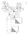
Die in Fig. 1 dargestellte Druckmaschine in der Vierfarbenversion enthält einen Druckzylinder
1 mit i = 3 Druckflächen 2.1; 2.2; 2.3 und i = 3 Greiferreihen 3.1, 3.2 und 3.3. Dem Druckzylinder
1 ist eine Bogenzuführeinrichtung, bestehend aus einem Vorderkantentrenner 4 und
einem Vorgreifersystem 6, zur Förderung eines zu bedruckenden Bogens von einem Anlegerbogenstapel
5 und Übergabe an den Druckzylinder 1 vorgeordnet. Die Zuführung der
Bogen zu dem Druckzylinder 1 erfolgt derart, daß nur jeder zweiten Greiferreihe 3 des
Druckzylinders ein Bogen zugeführt wird. Dem Druckzylinder 1 ist eine als Auslagekettenkreis
7 ausgebildete Bogenabführung zugeordnet, die den bedruckten Bogen vom Druckzylinder
1 übernimmt und zum Auslagebogenstapel 8 transportiert. Auch hier wird nur von jeder
zweiten Greiferreihe 3 des Druckzylinders 1 ein Bogen abgeführt.The printing machine shown in Fig. 1 in the four-color version contains a printing cylinder
1 with i = 3 printing areas 2.1; 2.2; 2.3 and i = 3 gripper rows 3.1, 3.2 and 3.3. The impression cylinder
1 is a sheet feeder consisting of a leading
Weiterhin sind dem Druckzylinder 1 zwei Zylindergruppen 11; 18 zugeordnet. Jede Zylindergruppe
enthält einen mit dem Druckzylinder 1 in Wirkverbindung stehenden Offsetzylinder 9
mit zwei Wirkflächen und einen mit dem Offsetzylinder 9 in Wirkverbindung stehenden
Druckformzylinder 10 mit zwei Wirkflächen.
Die Zylinder - Druckzylinder 1; Offsetzylinder 9 und Druckformzylinder 10 - sind in der Betriebsphasenlage
dargestellt, dabei stehen sich jeweils im Berührungspunkt der jeweiligen
Zylinder die Wirkflächen mit dem Druckanfang 29 gegenüber. In dieser Betriebsphasenlage
sind die Zylinder durch den Räderzug miteinander verbunden.
Die Druckanfänge 29 der Zylinder - Druckzylinder 1 und Offsetzylinder 9 der zweiten Zylindergruppe
18 - stehen sich in Fig. 1 wie dargestellt gegenüber.
Jeder Wirkfläche jedes Druckformzylinders 10 ist ein Farbwerk 19 zugeordnet. Das Farbwerk
19 enthält eine Auftragwalze 20.
Nach der in Fig. 1 dargestellten Ausführungsart ist das Farbwerk 19 als Aniloxfarbwerk ausgestaltet.
Das Aniloxfarbwerk enthält neben der Auftragwalze 20 eine Farbdosierwalze 23,
der ein Rakelkasten 24 zugeordnet ist.Furthermore, the cylinder 1 two
The cylinder - pressure cylinder 1;
The pressure starts 29 of the cylinders - pressure cylinder 1 and
An
According to the embodiment shown in Fig. 1, the
Die Druckmaschine gem. Fig. 1 ist mit zwei Zylindergruppen 11; 18 mit zwei Offsetzylindem
mit je zwei Wirkflächen, zwei Druckformzylindem mit je zwei Wirkflächen und vier Farbwerken
ausgestattet und arbeitet somit als Vierfarbenmaschine.
Bei Ausstattung der Druckmaschine mit zwei Offsetzylindem mit je einer Wirkfläche, zwei
Druckformzylindem mit je einer Wirkfläche und 2 Farbwerken arbeitet die Druckmaschine als
Zweifarbenmaschine. The printing machine acc. Fig. 1 is with two
If the printing machine is equipped with two offset cylinders, each with an effective area, two printing form cylinders, each with an effective area and 2 inking units, the printing machine works as a two-color machine.
Bei Ausstattung der Druckmaschine mit nur einem Offsetzylinder und einem Druckformzylinder arbeitet die Druckmaschine als Ein- bzw. Zweifarbenmaschine.When the press is equipped with only one offset cylinder and one printing form cylinder the printing press works as a one or two-color press.
In Fig. 2 ist der Antriebsräderzug der Druckmaschine in der Vierfarbversion mit zwei Zylindergruppen
dargestellt. Der Antriebsräderzug enthält einen Motor 12 mit einem Motorritzel
13, ein Zwischenrad 14, ein Druckzylinderantriebsrad 15, zwei Offsetzylinderantriebsräder
17, zwei Druckformzylinderantriebsräder 21, vier Auftragwalzenantriebsräder 22 und vier
Farbdosierantriebsräder 25. Dem Druckformzylinder ist je ein Eigenantrieb 26 zugeordnet.In Fig. 2 is the drive wheel train of the printing press in the four-color version with two cylinder groups
shown. The drive gear train includes a
Die Zuordnung des Eigenantriebes 26 und die Anordnung des Druckformzylinderantriebsrades
21 am Druckformzylinder 10 zeigt Fig. 3. Dem Druckformzylinder 10 ist über eine Phasenlagekupplung
27 das Druckformzylinderantriebsrad 21 zugeordnet. Das Druckformzylinderantriebsrad
21 ist in den Zahnradzug der Druckmaschine eingeordnet und kämmt mit
dem Offsetzylinderantriebsrad 17 und dem Auftragwalzenantriebsrad 22. Dem Druckformzylinder
10 ist über eine Metallbalgkupplung 28 der Eigenantrieb 26 zugeordnet. Der Eigenantrieb
ist als Elektromotor ausgebildet.The assignment of the self-
Das erfindungsgemäße Verfahren ist bei einer Druckmaschine mit einer Zylindergruppe 11
oder 18 dadurch gekennzeichnet, daß mittels der Phasenlagekupplung 27 die Antriebsverbindung
(Antriebsverbindung 4 - in der Betriebsphasenlage) zwischen Druckformzylinder 10
und dem Druckformzylinderantriebsrad 21 gelöst und damit quasi der Druckformzylinder aus
dem Antriebsräderzug ausgegliedert wird und der Druckformzylinder 10 von dem Eigenantrieb
26 in der Bebilderungsphase angetrieben wird.
Die Drehzahl des Druckformzylinders 10 beim Bebildern, d.h. die Bebilderungsgeschwindigkeit
liegt wesentlich über der maximalen Druckgeschwindigkeit und beträgt vorzugsweise
das 2-5fache derselben.
Damit wird erreicht, daß die Zeit zum Bebildern auf ein Minimum gesenkt wird und keine Beanspruchung
der übrigen Maschinenteile - die Druckmaschine befindet sich im Stillstandauftritt.
Nach der Bebilderung und Stillsetzen des Eigenantriebes wird der Druckformzylinder 10 in
der Betriebsphasenlage mittels der Phasenlagekupplung 27 wieder in den Antriebsräderzug
eingegliedert. Betriebsphasenlage bedeutet dabei, wie bereits ausgeführt, daß sich die
Druckanfänge 29 der in Wirkverbindung stehenden Zylinder gegenüberstehen und ein
Druckbetrieb möglich ist. The method according to the invention is characterized in a printing press with a
The rotational speed of the
This ensures that the time for imaging is reduced to a minimum and the other machine parts are not stressed - the printing press is at a standstill.
After the self-drive has been illustrated and stopped, the
Nach einer Weiterbildung des Antriebes wird im Druckbetrieb der Eigenantrieb 26 mit einem
Strom zur Bremsung der Druckmaschine und zur Verspannung des Antriebsräderzuges beaufschlagt.
Damit wird der ohnehin vorhandene Eigenantrieb dazu genutzt um eine Verspannung
des Antriebsräderzuges im Druckbetrieb zu gewährleisten. Der dem Eigenantrieb
zugeführte Strom liegt vorzugsweise im Bereich von 10 % des Stromes des Hauptantriebsmotors
12.
Da im Druckbetrieb die Stromaufnahme des Hauptantriebsmotors 12 Schwankungen unterworfen
ist, wird dem Eigenantrieb ein diesen Schwankungen angepaßter Strom zugeführt.
Zur Aus- und Eingliederung des Druckformzylinders in und aus dem Antrieb der Druckmaschine
ist es auch möglich (Fig. 4; 5) jedes Druckformzylinderantriebsrad 21 fest mit dem
Druckformzylinder zu verbinden und damit mit dem Druckformzylinder in Exzenterlagern 30
exzentrisch zu lagern.
Über ein Verdrehen des Exzenterlagers 30 wird die Antriebsverbindung zwischen Druckformzylinderantriebsrad
21 und dem Antriebsräderzug getrennt, damit der Druckformzylinder
aus dem Antriebsräderzug ausgegliedert und der Druckformzylinder von dem Eigenantrieb in
der Bebilderungsphase angetrieben werden kann.
Nach der Bebilderung und Stillsetzen des Eigenantriebes wird der Druckformzylinder 10 in
der Betriebsphasenlage mittels Verdrehen des Exzenterlagers 30 wieder in den Antriebsräderzug
eingegliedert. Betriebsphasenlage bedeutet dabei, daß sich die Druckanfänge der in
Wirkverbindung stehenden Zylinder gegenüberstehen und ein Druckbetrieb möglich ist.According to a further development of the drive, a current for braking the printing press and for bracing the drive wheel train is applied to the self-
Since the current consumption of the
By rotating the
After the self-drive has been imaged and stopped, the
Bei dem Verfahren bei einer Druckmaschine mit zwei Zylindergruppen werden mittels der
Phasenlagekupplungen 27 die Antriebsverbindungen (Antriebsverbindungen in den Betriebsphasenlagen)
zwischen den Druckformzylindem 10 und den Druckformzylinderantriebsrädem
21 gelöst und damit quasi die Druckformzylinder 10 aus dem Antriebsräderzug
ausgegliedert.
Durch den Eigenantrieb 26 werden die Druckformzylinder 10 nunmehr mit Bebilderungsgeschwindigkeit
angetrieben.
Dabei werden im Einholbetrieb, der in die Hochlaufphase des Eigenantriebes vom Stillstand
auf Bebilderungsgeschwindigkeit fällt, die Druckformzylinder 10 aus den jeweiligen Betriebsphasenlagen
in eine phasengleiche Lage relativ zu den Bebilderungseinrichtungen 16 gebracht.
Vorzugsweise ist die phasengleiche Lage der Druckformzylinder 10 relativ zu den
Bebilderungseinrichtungen 16 mit dem Druckanfang 29 identisch, d.h. daß zu Beginn des
Bebilderungsvorganges beide Druckformzylinder 10 mit ihren Druckanfängen der jeweiligen
Bebilderungseinrichtung 16 gegenüberstehen.
Nach dieser Synchronisation werden die Druckformzylinder 10 synchron mit Bebilderungsgeschwindigkeit
angetrieben.
Nach dem Bebilderungsvorgang werden die Druckformzylinder 10 wieder in ihre jeweiligen
Betriebsphasenlagen gebracht.
Dies erfolgt wie nachfolgend beschrieben:
Die Betriebsphasenlage des jeweiligen Druckformzylinders wird durch den Eigenantrieb 26
überfahren, d.h. der Eigenantrieb wird nach Passieren der Betriebsphasenlage gestoppt,
danach wird der Druckformzylinder in den Antriebsräderzug eingegliedert und mechanische
Mittel (Phasenkupplung) übernehmen bei Inbetriebnahme des Antriebsräderzuges das exakte
Anfahren der Betriebsphasenlage.
Bei einer anderen Variante wird die Betriebsphasenlage mit folgenden Verfahrensschritten
angefahren:
Der Eigenantrieb des Druckformzylinders wird vor Erreichung der Betriebsphasenlage gestoppt,
danach wird der Druckformzylinder in den Antriebsräderzug eingegliedert und mechanische
Mittel (Phasenkupplung) übernehmen bei Inbetriebnahme des Eigenantriebes das
exakte Anfahren der Betriebsphasenlage.
Danach wird nach einer Weiterbildung des Antriebes mindestens ein Eigenantrieb in der beschriebenen
Art und Weise mit einem Strom zur Bremsung der Druckmaschine und Verspannung
des Antriebsräderzuges beaufschlagt.In the case of the method in a printing press with two cylinder groups, the drive connections (drive connections in the operating phase positions) between the
The
In the overhaul mode, which falls from the standstill to the imaging speed in the run-up phase of the self-propulsion, the
After this synchronization, the
After the imaging process, the
This is done as described below:
The operating phase position of the respective printing form cylinder is overrun by the
In another variant, the operating phase is started with the following process steps:
The self-propulsion of the printing form cylinder is stopped before reaching the operating phase position, then the printing form cylinder is integrated into the drive wheel train and mechanical means (phase coupling) take over the exact starting of the operating phase position when the self-propulsion is started.
Thereafter, according to a further development of the drive, at least one self-drive in the manner described is supplied with a current for braking the printing press and bracing the drive wheel train.
Nach einer weiteren Ausgestaltung der Erfindung wird der an dem Druckformzylinder angeordnete
Eigenantrieb auch teilweise oder insgesamt für den Antrieb der Druckmaschine im
Druckbetrieb genutzt.
Diese Ausgestaltung ist in den Figuren 6 und 7 dargestellt und wird nachfolgend anhand des
Antriebsschemas der Druckmaschine in der Vierfarbversion mit zwei Zylindergruppen beschrieben.According to a further embodiment of the invention, the self-drive arranged on the printing form cylinder is also used in part or in total for driving the printing press in printing operation.
This configuration is shown in FIGS. 6 and 7 and is described below using the drive scheme of the printing press in the four-color version with two cylinder groups.
Den beiden Druckformzylindem mit den Druckformzylinderantriebsrädem 21 ist wie bereits
beschrieben je ein Eigenantrieb 26 zugeordnet. Der Antriebsräderzug der Druckmaschine
enthält neben den Druckformzylinderantriebsrädern 21 zwei Offsetzylinderantriebsräder 17,
ein Druckzylinderantriebsrad 15, zwei Auftragwalzenantriebsräder 22, ein Vorgreifersystemantriebsrad
31, ein Vorderkantentrennerantriebsrad 32, ein Auslagezwischenrad 33 und
ein Auslagekettenkreisantriebsrad 34.
Im Bebilderungsbetrieb sind die Druckformzylinderantriebsräder 21 nicht aktiv in den Antriebsräderzug
eingegliedert und die Eigenantriebe 26 treiben nur die Druckformzylinder an;
die Druckmaschine wird nicht angetrieben und befindet sich im Stillstand.
Unter nicht aktiver Eingliederung der Druckformzylinderantriebsräder 21 ist wie bereits beschrieben
entweder eine Trennung des jeweiligen Druckformzylinderantriebsrades 21 vom
Druckformzylinder über eine Kupplung oder ein Herauslösen des fest mit dem Druckformzylinder
verbundenen Druckformzylinderantriebsrades 21 aus dem Antriebsräderzug durch
Verschwenken der exzentrisch gelagerten Druckformzylinder einschließlich Druckformzylinderantriebsräder
21 zu verstehen.
Im Druckbetrieb sind bei der Ausgestaltung der Erfindung die Druckformzylinderantriebsräder
2 aktiv in den Antriebsräderzug eingegliedert und mindestens ein Eigenantrieb 26 treibt
die Druckmaschine insgesamt oder teilweise an.
Im Falle des Gesamtantriebes der Druckmaschine (Fig. 6) durch mindestens einen Eigenantrieb
26 entfällt der üblicherweise für den Antrieb der Druckmaschine vorgesehene Motor und
alle Baugruppen der Druckmaschine werden von mindestens einem Eigenantrieb 26 angetrieben.
Bei Verwendung von mehr als einem Eigenantrieb zum Antrieb der Druckmaschine sind die
Eigenantriebe zu synchronisieren.As already described, each of the two printing forme cylinders with the printing forme
In the imaging mode, the printing form
As already described, inactive incorporation of the printing forme
In printing operation, in the embodiment of the invention, the printing form cylinder drive wheels 2 are actively incorporated into the drive wheel train and at least one self-
In the case of the overall drive of the printing press (FIG. 6) by means of at least one self-
If more than one own drive is used to drive the printing press, the own drives must be synchronized.
Im Falle des Teilantriebes der Druckmaschine (Fig. 7) durch mindestens einen Eigenantrieb
26 werden beispielsweise nur die gleichförmig umlaufenden Baugruppen über deren Antriebsräder-
Druckformzylinderantriebsrad 15, Offsetzylinderantriebsräder 17, Druckformzylinderantriebsräder
21 und Auftragwalzenantriebsräder 22 - von mindestens einem Eigenantrieb
26 angetrieben.
Die ungleichförmig umlaufenden Baugruppen - Vorgreifer 6, Vorderkantentrenner 4, Auslagekettenkreis
7 -werden durch deren Antriebsräder- Vorgreifersystemantriebsrad 31, erstes
Zwischenrad 35, zweites Zwischenrad 36, drittes Zwischenrad 37, Vorderkantentrennerantriebsrad
32, Auslagezwischenrad 33, Auslagekettenkreisantriebsrad 34 - von dem
Motor 12 angetrieben.
Diese Variante ist vorteilhaft, da die Schwingungen verursachenden Antriebe einen eigenen
Antriebsräderzug besitzen.
Bei dieser Variante ist der Motor 12 mit dem Eigenantrieb oder den Eigenantrieben synchronisiert. In the case of the partial drive of the printing press (FIG. 7) by at least one
The non-uniformly rotating assemblies -
This variant is advantageous because the drives causing the vibrations have their own drive wheel train.
In this variant, the
Eine andere Zuordnung der anzutreibenden Baugruppen zum Motor und zu dem Eigenantrieb bzw. den Eigenantrieben ist auch möglich.Another assignment of the modules to be driven to the motor and the self-propulsion or self-propelled is also possible.
Das erfindungsgemäße Verfahren ist bei einer Druckmaschine mit einer Zylindergruppe dadurch
gekennzeichnet, daß die Antriebsverbindung (Antriebsverbindung in der Betriebsphasenlage)
zwischen Druckformzylinder und dem Antriebsräderzug getrennt, damit der Druckformzylinder
aus dem Antriebsräderzug ausgegliedert und der Druckformzylinder von dem
Eigenantrieb 26 in der Bebilderungsphase angetrieben wird. The method according to the invention is thereby in a printing press with a cylinder group
characterized in that the drive connection (drive connection in the operating phase position)
between the printing form cylinder and the drive wheel train, so that the printing form cylinder
separated from the drive wheel train and the printing form cylinder from the
Self-
- 11
- DruckzylinderImpression cylinder
- 22nd
- DruckflächePrinting area
- 2.12.1
- erste Druckflächefirst printing area
- 2.22.2
- zweite Druckflächesecond printing area
- 2.32.3
- dritte Druckflächethird printing area
- 33rd
- GreiferreiheRow of grippers
- 3.13.1
- erste Greiferreihefirst row of grabs
- 3.23.2
- zweite Greiferreihesecond row of grabs
- 3.33.3
- dritte Greiferreihethird row of grabs
- 44th
- VorderkantentrennerLeading edge separator
- 55
- AnlegerbogenstapelStack of feeder sheets
- 66
- VorgreifersystemForerunner system
- 77
- AuslagekettenkreisDelivery chain circle
- 88th
- AuslagebogenstapelDelivery sheet stack
- 99
- OffsetzylinderOffset cylinder
- 1010th
- DruckformzylinderPrinting form cylinder
- 1111
- erste Zylindergruppefirst cylinder group
- 1212th
- Motorengine
- 1313
- MotorritzelMotor pinion
- 1414
- ZwischenradIdler gear
- 1515
- DruckzylinderantriebsradPrinting cylinder drive wheel
- 1616
- BebilderungseinrichtungImaging device
- 1717th
- OffsetzylinderantriebsradOffset cylinder drive wheel
- 1818th
- zweite Zylindergruppesecond cylinder group
- 1919th
- FarbwerkInking unit
- 2020th
- AuftragwalzeApplicator roller
- 2121
- DruckformzylinderantriebsradPrinting forme cylinder drive wheel
- 2222
- AuftragwalzenantriebsradApplicator roller drive wheel
- 2323
- FarbdosierwalzeInk metering roller
- 2424th
- RakelkastenSqueegee box
- 2525th
- FarbdosierantriebsradColor metering drive wheel
- 2626
- EigenantriebSelf-propelled
- 2727
- Phasenlagekupplung Phase coupling
- 2828
- MetallbalgkupplungMetal bellows coupling
- 2929
- DruckanfangStart of printing
- 3030th
- ExzenterlagerEccentric bearing
- 3131
- VorgreifersystemantriebsradGripper system drive wheel
- 3232
- VorderkantentrennerantriebsradFront edge separator drive wheel
- 3333
- AuslagezwischenradIntermediate delivery wheel
- 3434
- AuslagekettenkreisantriebsradDelivery chain circuit drive gear
- 3535
- erstes Zwischenradfirst intermediate wheel
- 3636
- zweites Zwischenradsecond idler gear
- 3737
- drittes Zwischenradthird intermediate gear
Claims (18)
- Method of driving a printing machine with an integrated imaging device (16), a printing cylinder (1) and at least one cylinder group (11; 18), consisting of an offset cylinder (9) and a printing forme cylinder (10), at least one inking mechanism (19) associated with the printing forme cylinder (10) and a sheet feed and sheet discharge device, wherein the cylinders (1; 9; 10) inclusive of inking mechanism (19) are connected by a drive wheel train, characterised in thatthe drive of the printing forme cylinder (10) is disconnected from the drive wheel train,the printing forme cylinder (10) is driven by means of an own drive (26) in imaging operation at an imaging speed lying above the maximum printing speed andthe drive of the printing forme cylinder (10) is incorporated into the drive wheel train in an operating phase position in which the printing starts of the cylinders in operative connection are disposed opposite one another.
- Method of driving a printing machine according to claim 1, characterised in that in the case of arrangement of at least two cylinder groups (11; 18)the drive of the printing forme cylinder (10) is triggered by the drive wheel train,the printing forme cylinder (10) by means of a respective own drive (26)is, in collecting operation, brought out of the operating phase positions into a position of same phase relative to the imaging devices (16) andis, in imaging operation, driven synchronously at an imaging speed lying above the maximum printing speed,the printing forme cylinder (10) is brought into an operating phase position in which the print starts are disposed opposite the cylinders in operative connection andthe drive of the printing forme cylinder (10) is incorporated into the drive wheel train.
- Method of driving according to claim 1, characterised in that the imaging speed lies in the region of two to five times the maximum printing speed.
- Method of driving according to claim 2, characterised in that the collecting operation is integrated into the run-up phase of the own drive (26).
- Method of driving according to claim 2, characterised in that the operating phase position of the printing forme cylinder (10) is driven by the own drive (26) and the exact attainment of the operating phase position is realised by mechanical means after the incorporation of the printing forme cylinder into the drive wheel train on placing of the same into operation.
- Method of driving according to claim 2, characterised in that the operating phase position of the printing forme cylinder (10) is realised by stopping the own drive (26) before attainment of the operational phase position and the exact attainment of the operating phase position is realised by mechanical means after the incorporation of the printing forme cylinder into the drive wheel train and on placing of the own drive into operation.
- Method of driving according to claim 1, characterised in that at least one own drive is acted on in printing operation by a current for braking the printing machine.
- Method of driving a printing machine according to claim 1, characterised in that at least one own drive is acted on in printing operation by a current which is matched to the state of the printing machine and secures stressing of the drive wheel train.
- Method of driving a printing machine according to claim 7, characterised in that the current for braking lies in the region of 10% of the current of the main drive motor.
- Method of driving a printing machine according to claim 8, characterised in that the current for stressing lies in the region of 10% of the current matched to the state of the printing machine.
- Method of driving a printing machine according to claim 1, characterised in that the drive, which is fixedly connected with the printing forme cylinder, of the printing forme cylinder is released by means of rotation of eccentric bearings from the drive wheel train and is incorporated again after the imaging.
- Method of driving a printing machine according to claim 1, characterised in that the printing mechanism is driven wholly or at least partly by means of the own drive.
- Method of driving a printing machine according to claim 12, characterised in that the conformably rotating subassemblies of the printing machine are driven by at least one own drive and the non-conformably rotating subassemblies are driven by a drive motor synchronised with the own drive.
- Method of driving a printing machine according to claim 13, characterised in that the own drive is driven in synchronised manner.
- Equipment for driving a printing machine with an integrated imaging device (16), a printing cylinder (1) and at least one cylinder group (11; 18), consisting of an offset cylinder (9) and a printing forme cylinder (10), an inking mechanism (19) associated with the printing forme cylinder (10) and a sheet feed and sheet discharge device, wherein the cylinders (1; 9; 10) inclusive of inking mechanism (19) are connected by a drive wheel train, characterised in that an own drive (26) is associated with each printing forme cylinder (10), and the printing forme cylinder drive wheel (21) is arranged to be rotationally movable on an axle of the same and can be coupled by way of an axially acting phase position coupling (27) with the printing form cylinder (10) in an operating phase position in which the printing starts of the cylinders in operative connection are disposed opposite one another.
- Equipment for driving according to claim 15, characterised in that the own drive (26) is an electric motor flange-mounted at the axle of the printing forme cylinder (10) by way of a metal bellows coupling (28).
- Equipment for driving according to claim 15, characterised in that the printing forme cylinder (10) has i = 2 printing surfaces, an inking mechanism (19) is associated with each printing surface and the printing cylinder is equipped with i + 1 printing surfaces.
- Equipment for driving according to claim 15, characterised in that an own drive (16) is associated with each printing forme cylinder (10), the respective printing forme cylinder drive wheel (21) is fixedly connected with the printing forme cylinder (10) and each printing forme cylinder (10) is mounted in eccentric bearings for disconnecting and incorporating the printing forme cylinder drive wheel (21) from and into the drive wheel train.
Applications Claiming Priority (7)
| Application Number | Priority Date | Filing Date | Title |
|---|---|---|---|
| DE19723147 | 1997-06-03 | ||
| DE1997123147 DE19723147A1 (en) | 1997-06-03 | 1997-06-03 | Printer machine driving method |
| DE19748119 | 1997-10-31 | ||
| DE19748119A DE19748119B4 (en) | 1997-10-31 | 1997-10-31 | Method and device for driving a printing press |
| DE19807127 | 1998-02-20 | ||
| DE1998107127 DE19807127A1 (en) | 1997-06-03 | 1998-02-20 | Method and device for driving printing press with integrated imaging device for multicolour offset printing machines |
| PCT/DE1998/001528 WO1998055312A1 (en) | 1997-06-03 | 1998-06-02 | Method and device for driving a printing press with an integrated imaging device |
Publications (2)
| Publication Number | Publication Date |
|---|---|
| EP1009635A1 EP1009635A1 (en) | 2000-06-21 |
| EP1009635B1 true EP1009635B1 (en) | 2001-12-12 |
Family
ID=27217434
Family Applications (1)
| Application Number | Title | Priority Date | Filing Date |
|---|---|---|---|
| EP98936101A Expired - Lifetime EP1009635B1 (en) | 1997-06-03 | 1998-06-02 | Method and device for driving a printing press with an integrated imaging device |
Country Status (4)
| Country | Link |
|---|---|
| US (1) | US6393987B1 (en) |
| EP (1) | EP1009635B1 (en) |
| DE (1) | DE59802466D1 (en) |
| WO (1) | WO1998055312A1 (en) |
Families Citing this family (9)
| Publication number | Priority date | Publication date | Assignee | Title |
|---|---|---|---|---|
| JP4047993B2 (en) | 1999-01-04 | 2008-02-13 | 理想科学工業株式会社 | Stencil printing method |
| AU2002213798A1 (en) * | 2000-09-20 | 2002-04-02 | Koenig And Bauer Aktiengesellschaft | Printing unit |
| AU2002213796A1 (en) * | 2000-09-20 | 2002-04-02 | Koenig And Bauer Aktiengesellschaft | Printing unit |
| US6796239B2 (en) * | 2001-03-22 | 2004-09-28 | Heidelberger Druckmaschinen Ag | Method and device for driving a printing press |
| US6851368B2 (en) * | 2001-08-29 | 2005-02-08 | Heidelberger Druckmaschinen Ag | Rotary printing press having a switchable speed-change gear mechanism with plant gears |
| DE10249727B4 (en) | 2001-11-21 | 2008-06-26 | Heidelberger Druckmaschinen Ag | Printing machine with a central plate cylinder |
| US6918338B2 (en) * | 2003-01-30 | 2005-07-19 | Hewlett-Packard Development Company, L.P. | Printing system |
| DE202006004340U1 (en) * | 2006-03-18 | 2006-05-11 | Man Roland Druckmaschinen Ag | Sheetfed |
| DE102009018476A1 (en) * | 2008-05-15 | 2009-11-19 | Heidelberger Druckmaschinen Ag | Phase-correct engagement of different rotating cylinders |
Family Cites Families (11)
| Publication number | Priority date | Publication date | Assignee | Title |
|---|---|---|---|---|
| DE1168449B (en) * | 1962-05-02 | 1964-04-23 | Schnellressenfab Heidelberg | Device for turning the cylinders on and off of a multi-color sheet-fed rotary printing press |
| DE1210899B (en) * | 1962-07-06 | 1966-02-17 | Maschf Augsburg Nuernberg Ag | Equipment on multi-color sheet-fed rotary printing machines for controlling the printing devices for the individual printing units |
| DE3167482D1 (en) * | 1980-09-03 | 1985-01-10 | Crosfield Electronics Ltd | Improvements relating to rotary printing presses |
| DE3344131C2 (en) * | 1983-12-07 | 1995-04-20 | Metronic Geraetebau | Flexographic printing unit for packaging printing |
| US4936211A (en) * | 1988-08-19 | 1990-06-26 | Presstek, Inc. | Multicolor offset press with segmental impression cylinder gear |
| US5163368B1 (en) * | 1988-08-19 | 1999-08-24 | Presstek Inc | Printing apparatus with image error correction and ink regulation control |
| US4911075A (en) * | 1988-08-19 | 1990-03-27 | Presstek, Inc. | Lithographic plates made by spark discharges |
| DE19515077B4 (en) * | 1995-04-28 | 2005-07-28 | Heidelberger Druckmaschinen Ag | Process for imaging a printing form on a printing form cylinder in a printing unit of a rotary printing press with an inking unit |
| DE19612927B4 (en) * | 1995-05-11 | 2009-12-10 | Kodak Graphic Communications Canada Company, Burnaby | Printing machine and image forming method for a printing press |
| US5713287A (en) * | 1995-05-11 | 1998-02-03 | Creo Products Inc. | Direct-to-Press imaging method using surface modification of a single layer coating |
| DE19743770A1 (en) * | 1997-10-02 | 1999-04-08 | Heidelberger Druckmasch Ag | Method for operating a rotary printing press and device for carrying out the method |
-
1998
- 1998-06-02 DE DE59802466T patent/DE59802466D1/en not_active Expired - Lifetime
- 1998-06-02 WO PCT/DE1998/001528 patent/WO1998055312A1/en active IP Right Grant
- 1998-06-02 EP EP98936101A patent/EP1009635B1/en not_active Expired - Lifetime
-
1999
- 1999-11-22 US US09/450,630 patent/US6393987B1/en not_active Expired - Lifetime
Also Published As
| Publication number | Publication date |
|---|---|
| DE59802466D1 (en) | 2002-01-24 |
| WO1998055312A1 (en) | 1998-12-10 |
| EP1009635A1 (en) | 2000-06-21 |
| US6393987B1 (en) | 2002-05-28 |
Similar Documents
| Publication | Publication Date | Title |
|---|---|---|
| DE4303797C2 (en) | Rotary printing machine for printing sheets | |
| EP0919372B1 (en) | Printing unit for a rotary printing machine | |
| EP0710558B1 (en) | Rotary web printing press | |
| EP0846555B1 (en) | Drive for a printing machine | |
| EP0820861B1 (en) | Printing unit | |
| EP0835180A2 (en) | Sheet-fed, offset rotary press | |
| EP0839090A1 (en) | Sheet-feed offset rotary printing machine | |
| EP1009635B1 (en) | Method and device for driving a printing press with an integrated imaging device | |
| EP1157830B1 (en) | Device and method for changing the printing image during the operation of a printing press | |
| DE4102472A1 (en) | ROTARY PRINTING MACHINE FOR BOW PROCESSING | |
| DE19723147A1 (en) | Printer machine driving method | |
| DE102005018677A1 (en) | Drive for a printing machine or lacquering machine comprises a common geared traction mechanism having a freely rotating drive wheel arranged on each plate cylinder and/or printing cylinder | |
| EP0914943B1 (en) | Method for driving a printing machine having an integrated imaging device | |
| EP1961562B1 (en) | Method for operating a processing machine | |
| DE19822893A1 (en) | Method of driving printer with printing cylinder and group of cylinders | |
| DE3108806A1 (en) | "BOW OFFSETROTATION PRINTING MACHINE FOR THE OPTIONAL PRODUCTION OF SINGLE-SIDED MULTICOLOR PRINTING OR BEAUTIFUL AND REPRINTING" | |
| EP1426183B1 (en) | Method for a flying plate exchange in rotary offset sheet printing presses | |
| EP1872944B1 (en) | Method and device for powering printing plate cylinders | |
| DE19812226B4 (en) | Method and device for imaging | |
| DE19512865C2 (en) | Drive for convertible perfecting and reverse printing sheet-fed rotary presses | |
| DE10206891A1 (en) | Printing unit drive for web-fed rotary printing machine, has line shaft drive motor for jointly driving transfer cylinders of two printing units | |
| EP1114721B1 (en) | Method for simultaneous insertion of printing plates during automatic or semi-automatic printing plate exchange in printing machines | |
| EP1717027B1 (en) | Process and device for driving rotary bodies in a printing press | |
| DE19538546A1 (en) | Sheet offset rotary printing machine | |
| DE102020120998A1 (en) | Method for operating a printing press comprising a plurality of printing units one behind the other in the substrate path and a printing press with a plurality of printing units arranged one behind the other in the substrate path |
Legal Events
| Date | Code | Title | Description |
|---|---|---|---|
| PUAI | Public reference made under article 153(3) epc to a published international application that has entered the european phase |
Free format text: ORIGINAL CODE: 0009012 |
|
| 17P | Request for examination filed |
Effective date: 19991108 |
|
| AK | Designated contracting states |
Kind code of ref document: A1 Designated state(s): DE FR GB |
|
| 17Q | First examination report despatched |
Effective date: 20001122 |
|
| GRAG | Despatch of communication of intention to grant |
Free format text: ORIGINAL CODE: EPIDOS AGRA |
|
| GRAG | Despatch of communication of intention to grant |
Free format text: ORIGINAL CODE: EPIDOS AGRA |
|
| GRAH | Despatch of communication of intention to grant a patent |
Free format text: ORIGINAL CODE: EPIDOS IGRA |
|
| GRAH | Despatch of communication of intention to grant a patent |
Free format text: ORIGINAL CODE: EPIDOS IGRA |
|
| GRAA | (expected) grant |
Free format text: ORIGINAL CODE: 0009210 |
|
| AK | Designated contracting states |
Kind code of ref document: B1 Designated state(s): DE FR GB |
|
| REG | Reference to a national code |
Ref country code: GB Ref legal event code: IF02 |
|
| REF | Corresponds to: |
Ref document number: 59802466 Country of ref document: DE Date of ref document: 20020124 |
|
| GBT | Gb: translation of ep patent filed (gb section 77(6)(a)/1977) |
Effective date: 20020325 |
|
| ET | Fr: translation filed | ||
| PLBI | Opposition filed |
Free format text: ORIGINAL CODE: 0009260 |
|
| 26 | Opposition filed |
Opponent name: HEIDELBERGER DRUCKMASCHINEN AG Effective date: 20020729 |
|
| PLBF | Reply of patent proprietor to notice(s) of opposition |
Free format text: ORIGINAL CODE: EPIDOS OBSO |
|
| PLBF | Reply of patent proprietor to notice(s) of opposition |
Free format text: ORIGINAL CODE: EPIDOS OBSO |
|
| PLCK | Communication despatched that opposition was rejected |
Free format text: ORIGINAL CODE: EPIDOSNREJ1 |
|
| APBP | Date of receipt of notice of appeal recorded |
Free format text: ORIGINAL CODE: EPIDOSNNOA2O |
|
| APBQ | Date of receipt of statement of grounds of appeal recorded |
Free format text: ORIGINAL CODE: EPIDOSNNOA3O |
|
| APAA | Appeal reference recorded |
Free format text: ORIGINAL CODE: EPIDOS REFN |
|
| APBU | Appeal procedure closed |
Free format text: ORIGINAL CODE: EPIDOSNNOA9O |
|
| PLBN | Opposition rejected |
Free format text: ORIGINAL CODE: 0009273 |
|
| STAA | Information on the status of an ep patent application or granted ep patent |
Free format text: STATUS: OPPOSITION REJECTED |
|
| 27O | Opposition rejected |
Effective date: 20050203 |
|
| APAH | Appeal reference modified |
Free format text: ORIGINAL CODE: EPIDOSCREFNO |
|
| REG | Reference to a national code |
Ref country code: DE Ref legal event code: R081 Ref document number: 59802466 Country of ref document: DE Owner name: KOENIG & BAUER AG, DE Free format text: FORMER OWNER: KBA-PLANETA AG, 01445 RADEBEUL, DE |
|
| REG | Reference to a national code |
Ref country code: FR Ref legal event code: PLFP Year of fee payment: 19 |
|
| REG | Reference to a national code |
Ref country code: FR Ref legal event code: PLFP Year of fee payment: 20 |
|
| PGFP | Annual fee paid to national office [announced via postgrant information from national office to epo] |
Ref country code: DE Payment date: 20170531 Year of fee payment: 20 Ref country code: GB Payment date: 20170626 Year of fee payment: 20 Ref country code: FR Payment date: 20170626 Year of fee payment: 20 |
|
| REG | Reference to a national code |
Ref country code: DE Ref legal event code: R071 Ref document number: 59802466 Country of ref document: DE |
|
| REG | Reference to a national code |
Ref country code: GB Ref legal event code: PE20 Expiry date: 20180601 |
|
| PG25 | Lapsed in a contracting state [announced via postgrant information from national office to epo] |
Ref country code: GB Free format text: LAPSE BECAUSE OF EXPIRATION OF PROTECTION Effective date: 20180601 |