EP1009068A1 - Leiterplatten-Randverbinder für flache Schaltungen - Google Patents
Leiterplatten-Randverbinder für flache Schaltungen Download PDFInfo
- Publication number
- EP1009068A1 EP1009068A1 EP98119572A EP98119572A EP1009068A1 EP 1009068 A1 EP1009068 A1 EP 1009068A1 EP 98119572 A EP98119572 A EP 98119572A EP 98119572 A EP98119572 A EP 98119572A EP 1009068 A1 EP1009068 A1 EP 1009068A1
- Authority
- EP
- European Patent Office
- Prior art keywords
- actuator
- terminals
- housing
- contact portions
- slot
- Prior art date
- Legal status (The legal status is an assumption and is not a legal conclusion. Google has not performed a legal analysis and makes no representation as to the accuracy of the status listed.)
- Withdrawn
Links
Images


Classifications
-
- H—ELECTRICITY
- H01—ELECTRIC ELEMENTS
- H01R—ELECTRICALLY-CONDUCTIVE CONNECTIONS; STRUCTURAL ASSOCIATIONS OF A PLURALITY OF MUTUALLY-INSULATED ELECTRICAL CONNECTING ELEMENTS; COUPLING DEVICES; CURRENT COLLECTORS
- H01R24/00—Two-part coupling devices, or either of their cooperating parts, characterised by their overall structure
- H01R24/60—Contacts spaced along planar side wall transverse to longitudinal axis of engagement
- H01R24/62—Sliding engagements with one side only, e.g. modular jack coupling devices
-
- H—ELECTRICITY
- H01—ELECTRIC ELEMENTS
- H01R—ELECTRICALLY-CONDUCTIVE CONNECTIONS; STRUCTURAL ASSOCIATIONS OF A PLURALITY OF MUTUALLY-INSULATED ELECTRICAL CONNECTING ELEMENTS; COUPLING DEVICES; CURRENT COLLECTORS
- H01R12/00—Structural associations of a plurality of mutually-insulated electrical connecting elements, specially adapted for printed circuits, e.g. printed circuit boards [PCB], flat or ribbon cables, or like generally planar structures, e.g. terminal strips, terminal blocks; Coupling devices specially adapted for printed circuits, flat or ribbon cables, or like generally planar structures; Terminals specially adapted for contact with, or insertion into, printed circuits, flat or ribbon cables, or like generally planar structures
- H01R12/70—Coupling devices
- H01R12/82—Coupling devices connected with low or zero insertion force
- H01R12/85—Coupling devices connected with low or zero insertion force contact pressure producing means, contacts activated after insertion of printed circuits or like structures
- H01R12/87—Coupling devices connected with low or zero insertion force contact pressure producing means, contacts activated after insertion of printed circuits or like structures acting automatically by insertion of rigid printed or like structures
-
- H—ELECTRICITY
- H01—ELECTRIC ELEMENTS
- H01R—ELECTRICALLY-CONDUCTIVE CONNECTIONS; STRUCTURAL ASSOCIATIONS OF A PLURALITY OF MUTUALLY-INSULATED ELECTRICAL CONNECTING ELEMENTS; COUPLING DEVICES; CURRENT COLLECTORS
- H01R12/00—Structural associations of a plurality of mutually-insulated electrical connecting elements, specially adapted for printed circuits, e.g. printed circuit boards [PCB], flat or ribbon cables, or like generally planar structures, e.g. terminal strips, terminal blocks; Coupling devices specially adapted for printed circuits, flat or ribbon cables, or like generally planar structures; Terminals specially adapted for contact with, or insertion into, printed circuits, flat or ribbon cables, or like generally planar structures
- H01R12/50—Fixed connections
- H01R12/51—Fixed connections for rigid printed circuits or like structures
- H01R12/52—Fixed connections for rigid printed circuits or like structures connecting to other rigid printed circuits or like structures
Definitions
- This invention generally relates to the art of electrical connectors and, particularly, to connectors which commonly are called “edge card connectors" for receiving the edges of flat circuitry such as printed circuit boards.
- Such edge card connectors typically include an insulating or dielectric housing mountable on the primary or mother board.
- the housing has a card-receiving slot for receiving the edge of the secondary or daughter board.
- a plurality of terminals are mounted on the housing along one or both sides of the slot, and the terminals have flexible contact portions projecting into the slot for engaging appropriate circuit traces on one or both sides of the secondary circuit board.
- edge card connectors As described above is that the sharp edge of the inserted edge card engages and wipes the flexible contact portions of the terminals during insertion of the edge card into the card-receiving slot in the housing. At least the contact portions of the terminals typically are plated with a highly conductive precious metal.
- the substrate of the edge card typically is fabricated of abrasive material, such as glass fibers. If the lead-in edge of the card engages and wipes over the plated contact portions, degradation of the contact plating occurs.
- ZIF zero insertion force
- the present invention is directed to solving these problems by a very simple, efficient, cost-effective and unique system which employs a simple actuator mounted on and carried by the edge card, itself and allows at the same time to use a wide variety of daughter board thicknesses without degradation of the spring performance of the connector.
- An object, therefore, of the invention is to provide a new and improved electrical connector system of the character described, for terminating a flat circuit, such as the edge of a printed circuit board.
- the electrical connector system includes a dielectric housing having a pair of wings defining a circuit-receiving slot therebetween.
- a plurality of terminals are mounted on the housing, with contact portions of the terminals located at opposite sides of the slot.
- a flat circuit has an edge insertable into the slot.
- An actuator is mounted on and carried by the flat circuit. The actuator has actuator portions operatively associated with the terminals to bias the contact portions of the terminals into engagement with opposite sides of the flat circuit in response to inserting the edge of the circuit into the slot.
- the actuator portions of the actuator comprise actuator arms projecting toward the edge and extending generally parallel to the flat circuit.
- the arms are located a distance from the edge of the flat circuit such that the edge of the circuit passes the contact portions of the terminals before the contact portions are biased into engagement with opposite sides of the flat circuit.
- the terminals are mounted such that the contact portions thereof are exposed within the slot.
- the contact portions are fixed relative to the wings of the housing.
- the actuator portions are engageable with the wings to bias the wings and, in turn, the contact portions toward the slot and the flat circuit.
- the wings comprise independent portions of the housing movable relative to a body portion of the housing. Complementary interengaging cams are provided between the wings of the housing and the actuator portions of the actuator.
- the terminals are mounted such that the contact portions thereof are movable relative to the wings of the housing.
- the terminals include actuating portions coupled to the contact portions and engageable by the actuator portions of the actuator to bias the contact portions into engagement with opposite sides of the flat circuit.
- Each terminal is generally U-shaped to define a first leg forming the contact portion inside the wing at the slot, and a second leg forming the actuating portion exposed exteriorly of the slot.
- a first embodiment of an electrical connector system is shown to include an edge card connector, generally designated 12, for receiving an edge 14 of a flat circuit such as a printed circuit board 16.
- the circuit board is inserted into the connector in the direction of arrow "A" and carries therewith an actuator, generally designated 18. More particularly, connector 12 is adapted for mounting on a primary printed circuit board, "mother” board or backplane 20. If circuit board 20 is a “mother” board, circuit board 16 typically would be referred to as the secondary or “daughter” board. In any event, printed circuit board 16 will be referred to hereinafter as the edge card.
- Connector 12 includes a dielectric housing, generally designated 22, which includes a body portion 24 mounted to circuit board 20.
- the connector and body portion are elongated in a direction perpendicular to the drawings and include a forwardly projecting T-shaped flange 26.
- the housing includes a pair of wings 28 project forwardly of body portion 24 and terminate in pointed distal ends which define outside chamfered surfaces 28a and inside chamfered surfaces 28b.
- Wings 28 are independent portions of housing 22 and are mounted to body portion 24 by embracing T-shaped flange 26.
- the wings of the housing can pivot slightly relative to the body portion about points 30.
- the wings combine to form an elongated circuit or card receiving slot 32 therebetween.
- a plurality of terminals are mounted in two rows along elongated housing 22.
- Each terminal includes a tail portion 36 for connection, as by soldering or press-on, to circuit traces on a surface 20a of printed circuit board 20.
- the terminals are fixed within holes 38 in body portion 24 of the connector housing.
- the terminals have elongated U-shaped contact arms which project forwardly from body portion 24 into terminal-receiving passages 44 formed in wings 28.
- the U-shaped ends of the contact arms are wrapped around swivel bosses 42 spanning passages 40.
- the U-shaped configuration of the contact arms form inside legs defining contact portions 44 of the terminals and outside legs defining actuating portions 46 of the terminals.
- contact portions 44 are located within passages 40 and do not project into card-receiving slot 32. Actuating portions 46 project outwardly beyond the outside bounds of wings 28.
- edge 14 of edge card 16 is insertable in the direction of arrow "A" into slot 32 between wings 28 of connector 12.
- Actuator 18 is fixed to edge card 16 by appropriate means such as bolts, rivets or other appropriate fasteners 48.
- the actuator includes a pair of actuator arms 50 spaced from edge card 16.
- the actuator arms have inside cams 52.
- the actuator arms extend generally parallel to the edge card, and inside cams 52 are spaced inwardly of edge 14 of the card.
- FIG. 2 shows edge card 16 inserted only partially into slot 32 of connector 12. It can be seen that edge 14 of the edge card has passed contact portions 44 of terminals 34, but inside cams 52 of actuator arms 50 have not as yet engaged outside actuating portions 46 of the terminals. Therefore, edge 14 of the edge card will not damage or degrade the plating on contact portions 44 of the terminals. It should be noted that, during insertion, inside chamfered surfaces 28b of wings 28 help guide edge 14 of edge card 26 into slot 32. Outside chamfered surface 28a of the wings can engage inside cams 52 of actuator arms 50 to further guide the insertion action.
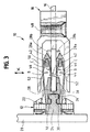
- Figure 3 shows edge card 16 fully inserted into connector 12. It can be seen that inside cams 52 of actuator arms 50 of actuator 18 have engaged actuating portions 46 of terminals 34 and have biased the actuating portions of the terminals inwardly in the direction of arrow "B". Because of the U-shaped configuration of the contact arms of the terminals, and because contact portions 44 of the terminals thereby are coupled with actuating portions 46, contact portions 44 swivel about swivel bosses 42 and move inwardly in the direction of arrows "C" into engagement with appropriate circuit traces on opposite sides of edge card 16.
- edge card and contact portions 44 Any wiping action between the edge card and contact portions 44 is limited to the smooth side surfaces of the edge card, rather than the abrupt edge 14 of the card, and only for a distance necessary to cause inside cams 52 of the actuator arms to effect movement of the terminals. It also should be understood that the actuating height or distance between actuator arms 50 and their inside cams 52 is totally independent of the thickness of edge card 16. For this reason the normal force reliability is independent of the daughter board thickness. It is possible to insert a thin daughter board into a connector which has accepted a thick multilayer board before without any degradation of normal forces. In addition the connector allows a certain misalignment in the "x" direction ( Figure 3) without affecting the normal forces.
- FIGS 4-6 show a second embodiment of an electrical connector system, generally designated 10A, embodying the concepts of the invention.
- System 10A includes an edge card connector, generally designated 12A, for receiving an edge card 16 which carries an actuator, generally designated 18A. Because of the general similarity between systems 10 and 10A, like reference numerals have been applied in Figures 4-6 corresponding to like components described above in relation to Figures 1-3.
- edge card 16 includes an insertion edge 14.
- Actuator 18A is fixed to the edge card by fastener(s) 48.
- the actuator has actuator arms 50 and inside cams 52.
- Connector 12A is mounted to a primary circuit board or backplane 20.
- the connector includes a housing 22 with a body portion 24 and a pair of wings 28 movable relative to the body portion about pivot bosses 30.
- Two rows of terminals, generally designated 34 are mounted to the body portion of the housing and have tail portions 36 connected to circuit traces on circuit board 20.
- Generally U-shaped contact arms of the terminals define contact portions 44 at opposite sides of a card-receiving slot 32.
- There are two rows of terminals extending longitudinally of the connector, and the contact arms of the terminals extend into terminal-receiving passages 44 in wings 28.
- terminals 34 having legs 60 fixed within partitions 62 which span passages 40 of wings 28.
- the housing components of either connectors 12 or 12A can be fabricated of dielectric material such as plastic or the like. Therefore, terminals arms 60 can be overmolded within partitions 62. With terminal arms 60 being fixed relative to the wings, contact portions 44 permanently project into slot 32.
- the outsides of wings 28 are provided with outside cams 64 which are engageable with inside cams 52 of actuator arms 50 of actuator 18A.
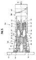
- Figure 5 shows edge card 16 only partially inserted into slot 32 of connector 12A between wings 28. It can be seen that edge 14 of the edge card has passed contact portions 44 of the terminals, and inside cams 52 of the actuator have not as yet engaged outside cams 64 of the wings. Therefore, the sharp edge 14 of the edge card will engage the contact portions with minimum or negligible forces not sufficient to cause significant damage or degradation to the plating on the contact portions.
- Figure 6 shows edge card 16 fully inserted into slot 32 of connector 12A. It can be seen that inside cams 52 of actuator arms 50 of actuator 18A have engaged outside cams 64 of wings 28 to bias the wings inwardly toward the edge card in the direction of arrows "D". With contact arms 60 and contact portions 44 fixed to partitions 62 of the wings, this biasing action is effective to bias contact portions 44 inwardly into positive engagement with appropriate circuit traces on opposite sides of edge card 16. Again, the distance between actuator arms 50 and their inside cams 52 is totally independent of the thickness of circuit card 16.
Landscapes
- Coupling Device And Connection With Printed Circuit (AREA)
Priority Applications (3)
| Application Number | Priority Date | Filing Date | Title |
|---|---|---|---|
| EP98119572A EP1009068A1 (de) | 1998-10-16 | 1998-10-16 | Leiterplatten-Randverbinder für flache Schaltungen |
| US09/417,005 US6238226B1 (en) | 1998-10-16 | 1999-10-12 | Edge connector for flat circuitry |
| KR1019990044681A KR20000035013A (ko) | 1998-10-16 | 1999-10-15 | 평면 회로용 에지 커넥터 |
Applications Claiming Priority (1)
| Application Number | Priority Date | Filing Date | Title |
|---|---|---|---|
| EP98119572A EP1009068A1 (de) | 1998-10-16 | 1998-10-16 | Leiterplatten-Randverbinder für flache Schaltungen |
Publications (1)
| Publication Number | Publication Date |
|---|---|
| EP1009068A1 true EP1009068A1 (de) | 2000-06-14 |
Family
ID=8232809
Family Applications (1)
| Application Number | Title | Priority Date | Filing Date |
|---|---|---|---|
| EP98119572A Withdrawn EP1009068A1 (de) | 1998-10-16 | 1998-10-16 | Leiterplatten-Randverbinder für flache Schaltungen |
Country Status (3)
| Country | Link |
|---|---|
| US (1) | US6238226B1 (de) |
| EP (1) | EP1009068A1 (de) |
| KR (1) | KR20000035013A (de) |
Cited By (4)
| Publication number | Priority date | Publication date | Assignee | Title |
|---|---|---|---|---|
| WO2007071532A1 (de) * | 2005-12-20 | 2007-06-28 | Robert Bosch Gmbh | Kontaktierungssteckverbindung |
| WO2010069741A1 (de) * | 2008-12-19 | 2010-06-24 | Robert Bosch Gmbh | Kontaktierungsstecker sowie kontaktierungsverbindung |
| WO2013000610A1 (de) * | 2011-06-29 | 2013-01-03 | Robert Bosch Gmbh | Steckverbinder mit rampen in der steckeraufnahme |
| EP2634864A3 (de) * | 2012-03-02 | 2014-05-21 | Robert Bosch GmbH | Leiterplattenvorrichtung und eine diesbezügliche elektrische Anordnung |
Families Citing this family (19)
| Publication number | Priority date | Publication date | Assignee | Title |
|---|---|---|---|---|
| US6346012B1 (en) * | 1998-08-15 | 2002-02-12 | Delta Electronics, Inc. | Locking cartridge for conveniently locking very thin connector with near-zero inductance onto PC board |
| FR2803110B1 (fr) * | 1999-12-22 | 2002-05-17 | Framatome Connectors Int | Connecteur pour carte a microcircuit et procede de montage d'une telle carte dans ce connecteur |
| JP3669268B2 (ja) * | 2000-11-30 | 2005-07-06 | 住友電装株式会社 | コネクタ |
| US6527573B2 (en) * | 2001-05-22 | 2003-03-04 | Delphi Technologies, Inc. | Slide contact electrical connector |
| US6867554B2 (en) * | 2001-12-03 | 2005-03-15 | International Rectifier Corporation | Ballast control card |
| US6796822B2 (en) * | 2002-07-02 | 2004-09-28 | Fujitsu Component Limited | Contact module and connector having the same |
| US6790054B1 (en) | 2003-03-18 | 2004-09-14 | Sullins Electronic Corporation | Two-piece right angle contact edge card connector |
| US20060225904A1 (en) * | 2005-04-12 | 2006-10-12 | Interflow Corp. | Power tool that can interrupt the electric power automatically |
| EP1736910B1 (de) * | 2005-06-23 | 2008-02-27 | ddm hopt + schuler GmbH & Co. KG. | Kartenleser mit symmetrischer Kontaktfeder |
| CN101297442B (zh) * | 2005-10-26 | 2012-08-08 | 艾利森电话股份有限公司 | 关于板连接的装置 |
| TWI321873B (en) * | 2006-07-10 | 2010-03-11 | Fci Connectors Singapore Pte | High speed connector |
| US7798855B2 (en) * | 2007-12-14 | 2010-09-21 | Caterpillar Inc | Connector for sensor assembly |
| KR100833532B1 (ko) * | 2008-02-21 | 2008-05-29 | 주식회사 광명전기 | 통전용량과 절연성능을 향상시킨 전동기 제어반 |
| KR101283639B1 (ko) * | 2010-09-16 | 2013-07-08 | 주식회사 오킨스전자 | 모듈과 소켓핀의 보호가 가능한 모듈소켓 |
| US8641438B2 (en) * | 2011-07-11 | 2014-02-04 | Denso Corporation | Electronic device having card edge connector |
| JP6356504B2 (ja) * | 2014-06-25 | 2018-07-11 | 矢崎総業株式会社 | コネクタ |
| DE202015003001U1 (de) * | 2015-04-23 | 2015-06-25 | Rosenberger Hochfrequenztechnik Gmbh & Co. Kg | Stecksystem mit verschleißarmer Kontaktierung |
| US9583845B1 (en) * | 2015-10-27 | 2017-02-28 | Dell Products, Lp | Electrical connector for an information handling system |
| JP6372675B1 (ja) * | 2017-12-14 | 2018-08-15 | Smk株式会社 | カードエッジ接続装置 |
Citations (5)
| Publication number | Priority date | Publication date | Assignee | Title |
|---|---|---|---|---|
| US3478301A (en) * | 1967-04-06 | 1969-11-11 | Itt | Low insertion force cam-actuated printed circuit board connector |
| US3778753A (en) * | 1972-05-05 | 1973-12-11 | Bunker Ramo | Electrical connector |
| US4118094A (en) * | 1977-03-31 | 1978-10-03 | Trw Inc. | Zero-entry force connector |
| US4448466A (en) * | 1981-11-12 | 1984-05-15 | Ncr Corporation | Low insertion force connector for printed circuit boards |
| DE4018947A1 (de) * | 1990-06-13 | 1992-01-09 | Stocko Metallwarenfab Henkels | Vorrichtung zum elektrischen verbinden von leiterplatten |
Family Cites Families (28)
| Publication number | Priority date | Publication date | Assignee | Title |
|---|---|---|---|---|
| US3474387A (en) * | 1967-04-13 | 1969-10-21 | Elco Corp | Zero insertion force connector and contact therefor |
| US4021091A (en) * | 1975-06-13 | 1977-05-03 | International Telephone And Telegraph Corporation | Zero force printed circuit board connector |
| EP0036933A3 (de) * | 1980-03-28 | 1981-12-02 | Bohdan Ulrich | Steckverbinder und Verwendung desselben zur Herstellung einer lösbaren elektrischen Verbindung |
| US4428635A (en) * | 1982-02-24 | 1984-01-31 | Amp Incorporated | One piece zif connector |
| JPS6071090U (ja) | 1983-10-24 | 1985-05-20 | 第一電子工業株式会社 | 零挿抜カコネクタ |
| US4530553A (en) * | 1984-03-15 | 1985-07-23 | Northern Telecom Limited | Minimum insertion force connector |
| US4560221A (en) | 1984-05-14 | 1985-12-24 | Amp Incorporated | High density zero insertion force connector |
| US4684194A (en) | 1984-07-16 | 1987-08-04 | Trw Inc. | Zero insertion force connector |
| US4613193A (en) | 1984-08-13 | 1986-09-23 | Tritec, Inc. | Board-operated electrical connector for printed circuit boards |
| US4720156A (en) | 1984-08-13 | 1988-01-19 | Tritec, Inc. | Manually operated electrical connector for printed circuit boards |
| US4611870A (en) | 1984-08-13 | 1986-09-16 | Tritec, Inc. | Manually operated electrical connector for printed circuit boards |
| US4606594A (en) | 1985-04-22 | 1986-08-19 | Amp Incorporated | ZIF connector with wipe |
| US4705338A (en) | 1985-12-13 | 1987-11-10 | E. I. Du Pont De Nemours And Company | Zero insertion force connector |
| US4695111A (en) | 1986-04-10 | 1987-09-22 | Amp Incorporated | Zero insertion force connector having wiping action |
| US4648668A (en) | 1986-06-26 | 1987-03-10 | Amp Incorporated | Zero insertion force card edge connector |
| DE3750064T2 (de) | 1986-09-10 | 1994-09-22 | Furukawa Electric Co Ltd | Ein elektronischer Verbinder. |
| US4743203A (en) | 1987-05-07 | 1988-05-10 | Amp Incorporated | Camming means for use with a low insertion force connector |
| US4815979A (en) | 1987-12-23 | 1989-03-28 | Ncr Corporation | Right angle electrical connector with or without wiping action |
| US4904197A (en) | 1989-01-13 | 1990-02-27 | Itt Corporation | High density zif edge card connector |
| US4863395A (en) | 1989-01-17 | 1989-09-05 | Robert Babuka | Zero insertion force connector with component card |
| US4919626A (en) * | 1989-04-14 | 1990-04-24 | Itt Corporation | Connector for IC card |
| JPH04245183A (ja) | 1990-09-07 | 1992-09-01 | Rogers Corp | フレキシブル回路エッジボードコネクタ |
| US5308249A (en) | 1993-06-16 | 1994-05-03 | The Whitaker Corporation | Backplane connector utilizing flexible film circuitry |
| US5391089A (en) * | 1993-08-26 | 1995-02-21 | Becton, Dickinson And Company | Cam action electrical edge connector |
| GB9508690D0 (en) | 1995-04-28 | 1995-06-14 | Amp Gmbh | Zero insertion force connector with wiping action |
| JPH0992410A (ja) | 1995-09-22 | 1997-04-04 | Sumitomo Wiring Syst Ltd | カードエッジコネクタ |
| US5679018A (en) | 1996-04-17 | 1997-10-21 | Molex Incorporated | Circuit card connector utilizing flexible film circuitry |
| JP2871606B2 (ja) | 1996-07-22 | 1999-03-17 | 日本電気株式会社 | 活線挿抜対応コネクタ |
-
1998
- 1998-10-16 EP EP98119572A patent/EP1009068A1/de not_active Withdrawn
-
1999
- 1999-10-12 US US09/417,005 patent/US6238226B1/en not_active Expired - Lifetime
- 1999-10-15 KR KR1019990044681A patent/KR20000035013A/ko not_active Application Discontinuation
Patent Citations (5)
| Publication number | Priority date | Publication date | Assignee | Title |
|---|---|---|---|---|
| US3478301A (en) * | 1967-04-06 | 1969-11-11 | Itt | Low insertion force cam-actuated printed circuit board connector |
| US3778753A (en) * | 1972-05-05 | 1973-12-11 | Bunker Ramo | Electrical connector |
| US4118094A (en) * | 1977-03-31 | 1978-10-03 | Trw Inc. | Zero-entry force connector |
| US4448466A (en) * | 1981-11-12 | 1984-05-15 | Ncr Corporation | Low insertion force connector for printed circuit boards |
| DE4018947A1 (de) * | 1990-06-13 | 1992-01-09 | Stocko Metallwarenfab Henkels | Vorrichtung zum elektrischen verbinden von leiterplatten |
Cited By (6)
| Publication number | Priority date | Publication date | Assignee | Title |
|---|---|---|---|---|
| WO2007071532A1 (de) * | 2005-12-20 | 2007-06-28 | Robert Bosch Gmbh | Kontaktierungssteckverbindung |
| US7654845B2 (en) | 2005-12-20 | 2010-02-02 | Robert Bosch Gmbh | Contacting plug-and-socket connection with contact force independent of contact carrier thickness |
| WO2010069741A1 (de) * | 2008-12-19 | 2010-06-24 | Robert Bosch Gmbh | Kontaktierungsstecker sowie kontaktierungsverbindung |
| US8636530B2 (en) | 2008-12-19 | 2014-01-28 | Robert Bosch Gmbh | Contacting plug as well as contacting connection |
| WO2013000610A1 (de) * | 2011-06-29 | 2013-01-03 | Robert Bosch Gmbh | Steckverbinder mit rampen in der steckeraufnahme |
| EP2634864A3 (de) * | 2012-03-02 | 2014-05-21 | Robert Bosch GmbH | Leiterplattenvorrichtung und eine diesbezügliche elektrische Anordnung |
Also Published As
| Publication number | Publication date |
|---|---|
| KR20000035013A (ko) | 2000-06-26 |
| US6238226B1 (en) | 2001-05-29 |
Similar Documents
| Publication | Publication Date | Title |
|---|---|---|
| US6238226B1 (en) | Edge connector for flat circuitry | |
| US6162083A (en) | Electrical connector system for flat circuitry | |
| US5582519A (en) | Make-first-break-last ground connections | |
| EP0411888B1 (de) | Elektrischer Steckverbinder | |
| US6364711B1 (en) | Filtered electrical connector | |
| EP0667651B1 (de) | Elektrischer Verbinder | |
| EP2493023A2 (de) | Elektrischer Steckverbinder | |
| EP0510995A2 (de) | Elektrischer Verbinder mit zuverlässigen Anschlüssen | |
| EP0602443A2 (de) | Vorrichtung für die Befestigung eines Steckverbinders auf einer Leiterplatte | |
| EP0961352B1 (de) | Mehrpoliger Flachkabelverbinder | |
| US20160006192A1 (en) | Electrical connector having electrical contacts that engage mating contacts | |
| US6866552B2 (en) | Electrical connector with a terminal pin alignment plate | |
| US5292265A (en) | Edge mounted circuit board electrical connector | |
| US5893764A (en) | Board straddle mounted electrical connector | |
| EP0530964B1 (de) | Elektrischer Verbinder mit verbesserter Erdungsschiene | |
| JPH08180940A (ja) | 電気コネクタ | |
| US4919626A (en) | Connector for IC card | |
| US6135785A (en) | Small pitch electrical connector having narrowed portion | |
| US6793541B2 (en) | Circuit board connector with improved terminal tails | |
| US5470246A (en) | Low profile edge connector | |
| US5167544A (en) | Female electrical contact | |
| US6015310A (en) | Electrical connector for flat circuitry | |
| EP0065357B1 (de) | Steckverbinder mit einer schwachen Einführkraft | |
| US10535947B1 (en) | Signal transmission assembly, floating connector, and conductive terminal of floating connector | |
| US4066327A (en) | Electrical connector assemblies |
Legal Events
| Date | Code | Title | Description |
|---|---|---|---|
| PUAI | Public reference made under article 153(3) epc to a published international application that has entered the european phase |
Free format text: ORIGINAL CODE: 0009012 |
|
| AK | Designated contracting states |
Kind code of ref document: A1 Designated state(s): DE FR GB IT NL SE |
|
| AX | Request for extension of the european patent |
Free format text: AL;LT;LV;MK;RO;SI |
|
| RIN1 | Information on inventor provided before grant (corrected) |
Inventor name: ENDRES, HERBERT Inventor name: SCHEMPP, OTTO |
|
| 17P | Request for examination filed |
Effective date: 20001207 |
|
| AKX | Designation fees paid |
Free format text: DE FR GB IT NL SE |
|
| STAA | Information on the status of an ep patent application or granted ep patent |
Free format text: STATUS: THE APPLICATION HAS BEEN WITHDRAWN |
|
| 18W | Application withdrawn |
Withdrawal date: 20010830 |