EP1008467A1 - Method of mounting a tyre on a rim and device for carrying out a step of this method - Google Patents
Method of mounting a tyre on a rim and device for carrying out a step of this method Download PDFInfo
- Publication number
- EP1008467A1 EP1008467A1 EP99123826A EP99123826A EP1008467A1 EP 1008467 A1 EP1008467 A1 EP 1008467A1 EP 99123826 A EP99123826 A EP 99123826A EP 99123826 A EP99123826 A EP 99123826A EP 1008467 A1 EP1008467 A1 EP 1008467A1
- Authority
- EP
- European Patent Office
- Prior art keywords
- bead
- gripping means
- rim
- tire
- seat
- Prior art date
- Legal status (The legal status is an assumption and is not a legal conclusion. Google has not performed a legal analysis and makes no representation as to the accuracy of the status listed.)
- Granted
Links
Images
Classifications
-
- B—PERFORMING OPERATIONS; TRANSPORTING
- B60—VEHICLES IN GENERAL
- B60C—VEHICLE TYRES; TYRE INFLATION; TYRE CHANGING; CONNECTING VALVES TO INFLATABLE ELASTIC BODIES IN GENERAL; DEVICES OR ARRANGEMENTS RELATED TO TYRES
- B60C25/00—Apparatus or tools adapted for mounting, removing or inspecting tyres
- B60C25/01—Apparatus or tools adapted for mounting, removing or inspecting tyres for removing tyres from or mounting tyres on wheels
- B60C25/02—Tyre levers or the like, e.g. hand-held
Definitions
- the present invention relates to a method of mounting a tire on a rim and a device for implementing a step of this process. More precisely, this rim is such that it has peripheral edges seats respectively intended to receive the beads of the tire.
- such a rim 30 has the following features.
- a first and a second rim seats 32 inclined outwards and respectively intended for receive a first and a second bead 21 of the tire 20 (only one first projection 31, a first seat 32 and the corresponding bead 21 are represented).
- a range 33 intended to receive a tread support support 22 for said tire 20 and, on the other hand, a mounting groove 34 connecting said bearing surface 33 to a flange axially internal 32a of said first seat 32.
- first seat 32 the seat which is adjacent to the groove 34
- second seat the seat which is opposite at said groove 34
- the axially external rim of the seat 32 As for the axially external rim of the seat 32, it is formed by the projection corresponding device 31.
- the first bead 21 is extracted from the groove 34 so as to bring it axially outside the projection 31 of the first seat 32.
- this first bead 21 is mounted on the first seat 32.
- a major drawback of this procedure is the duration relatively important to carry out this extraction over the entire circumference of the pneumatic and, therefore, in the unsuitability of this technique for carrying out in series of mounted assemblies incorporating this type of rims.
- said tire is rotated around its axis of revolution, said gripping means occupying said extraction position local.
- a second embodiment of said fourth step is inserted under said internal face of said first bead, at another point of the circumference of said tire, the substantially flat base of a curved lug in the shape of an ⁇ L ⁇ , said tire, said rim and said gripping means being integrally driven in rotation relative to said tab.
- Another object of the present invention is to provide a device for the extraction of said first bead comprising a frame and a platform intended for receive said rim provided with said tire perpendicular to the axis of revolution of the latter, a gripping means intended to press on the internal face said first bead being pivotally mounted on a first pivot axis, movable relative to said frame and parallel to the plane of said platform, this device providing, in series operation, the aforementioned result of assembly rate relatively high.
- said device is such that said gripping means is coupled, via a link, to a control means provided for controlling the pivoting of said gripping means around a second axis of pivoting, fixedly mounted on said frame and also parallel to the plane of said platform.
- said link is articulated on said pivot axes.
- Said gripping means is for example provided with an arm provided for pivot it so that said gripping means form substantially the oblique branch of a ⁇ y ⁇ whose leg is formed by said arm, said first pivot axis being mounted at one end of said arm which is opposite the free end of said gripping means.
- said gripping means has a curvature which admits substantially for center said first pivot axis.
- said gripping means has a free end tapered and chamfered side edges in a middle portion of said means of gripping, where its radius of curvature is substantially maximum.
- said device comprises a finger intended to press on said tire, said finger being mounted along the side of said arm which is opposite to that of said gripping means and also being controlled by said control means.
- said frame is provided with locking means for locking said control means in said extraction position.
- control means and / or said arm and / or said finger are provided with cylinders respectively provided for actuating them.
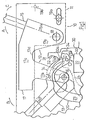
- a device 10 for the extraction of a tire 20 from said rim groove 34 30 essentially comprises a frame 11, a platform (not shown in Figs. 1 and 2) which is intended to receive the rim 30 provided with the tire 20 perpendicular to the axis of revolution of the latter and which is provided below said frame 11, and means 12 mounted on the frame 11 and provided to cooperate with said first bead 21 of the tire 20 for said extraction.
- These means 12 essentially comprise at least one finger 13 which is intended to press on the sidewall 24 of the tire 20 ending with the first bead 21, a pivoting gripping means 14 intended to press on the internal face 21a of said first bead 21, and a control means 15 provided for controlling the pivoting of said gripping means 14.
- the gripping means 14 is pivotally mounted on a first axis of pivot 16 parallel to the plane of said platform.
- the gripping means 14 is provided with a arm 14a provided for pivoting actuation, such that said means of grip 14 substantially forms the oblique branch of a ⁇ y ⁇ whose leg would be formed by said arm 14a.
- the first axis of pivot 16 is mounted at one end of the arm 14a which is opposite the end free 14b of said gripping means 14.
- said finger 13 is mounted on the side of the arm 14a which is opposite to that of the gripping means 14.
- the gripping means 14 has a curvature giving it a hook shape. This curvature substantially admits the first axis as its center pivot 16, and the aforesaid free end 14b is tapered.
- the side edges 14c of the gripping means 14 are preferably chamfered, this in a middle part of said means of grip 14. As can be seen in FIG. 1, this middle part has a substantially maximum radius of curvature.
- the gripping means 14 is coupled to said control means 15 by via a link 17, so that it can pivot around a second pivot axis 18 under the control of said means 15, which is integral with the link 17.
- This second axis 18 is fixedly mounted on the frame 11 parallel to the plane of said platform.
- this link 17 is mounted, on the one hand, on said first axis 16 and, on the other hand, on said second axis 18.
- this link 17 is consisting of two legs 17a and 17b which are respectively mounted on said axes 16 and 18, and which are connected together by a section 17c, so that said connecting rod 17 has between said legs 17a and 17b a recess 17d giving it substantially a form of ⁇ .
- control means 15 consists of an arm whose axis of symmetry 15a passes through said second axis 18.
- a device 10 according to the invention also comprises means 19a, 19b to block the control means 15 in a determined position.
- these consist of two removable stops 19a and 19b.
- This device 10 operates in the following manner, once the first bead 21 has been positioned in the groove 34, as shown in solid lines at the Fig. 1 (the other bead being fitted in said second seat).
- this actuation is carried out by rotating the control means 15 in the direction of arrow A.
- this actuation is carried out by rotating the control means 15 in the direction of arrow A.
- other modes of actuation of this finger 13 could be used.
- this finger 13 could be mounted otherwise, provided that it can press said flank 24 so as to create said local space.
- the arm is then rotated 14a on the first pivot axis 16 in the direction of arrow B, so as to insert the gripping means 14 in said local space.
- the end 14b of the gripping means 14 is radially inside the bead 21.
- the thick, chamfered structure of the middle part of the gripping means 14 is well suited for pressing on the bead 21 without the deform.
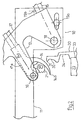
- control means 15 are pivoted around the second axis of pivoting 18 and in the direction of arrow C, the gripping means 14 occupying always said support position, which also has the effect of rotating said gripping means 14 around said axis 18 via the link 17. We interrupt this pivoting when the gripping means 14 has reached the final position of local extraction of FIG. 2.
- this final position is such that the bead 21 then occupies a position radially and axially outside the seat 32 correspondent.
- the platform is activated. so as to rotate it on itself, so that the tire 20 and the rim 30 rotates integrally around their axis of revolution, the means extraction 12 remaining stationary.
- This rotation of the tire 20 and the rim 30 has the effect, in one single revolution, to extract the bead 21 around the entire circumference of the pneumatic 20.
- said tab 17a of the link 17 has, at near the free end of its inner edge which is intended to face the bead 21 extracted (position of FIG. 2), a shape adapted not to enter contact with this bead 21 during the aforementioned rotation of the tire 20, this in order to not to hinder it.
- this form can be of type locally re-entrant, for example rounded, like the rear (dotted) part of the gripping means 14 which is notably visible in FIG. 2.
- This rotation of the tire 20 also has the effect, in a single revolution, to extract the bead 21 over the entire circumference of the tire 20.
- a device 10 according to the invention for setting up work of the entire bead extraction step 21 could advantageously comprise cylinders respectively provided for actuating the aforementioned manner said control means 15 and / or said arm 14a and / or said finger 13.
Abstract
Description
La présente invention concerne un procédé de montage d'un pneumatique sur une jante et un dispositif pour la mise en oeuvre d'une étape de ce procédé. Plus précisément, cette jante est telle qu'elle comporte en ses rebords périphériques des sièges respectivement destinés à recevoir les bourrelets du pneumatique.The present invention relates to a method of mounting a tire on a rim and a device for implementing a step of this process. More precisely, this rim is such that it has peripheral edges seats respectively intended to receive the beads of the tire.
En relation avec les Figs. 1 et 2 ci-après présentées, une telle jante 30 présente
les caractéristiques suivantes.In relation to Figs. 1 and 2 below presented, such a
Elle comporte, à partir de ses deux saillies périphériques 31, un premier et un
second sièges de jante 32 inclinés vers l'extérieur et respectivement destinés à
recevoir un premier et un second bourrelets 21 du pneumatique 20 (seuls une
première saillie 31, un premier siège 32 et le bourrelet 21 correspondants sont
représentés). Entre les sièges 32 est prévue, d'une part, une portée 33 destinée à
recevoir un appui 22 de soutien de bande de roulement 23 pour ledit pneumatique 20
et, d'autre part, une gorge de montage 34 reliant ladite portée 33 à un rebord
axialement interne 32a dudit premier siège 32.It comprises, from its two
Dans la suite de la présente description, on appellera par convention premier
siège 32 le siège qui est adjacent à la gorge 34, et second siège le siège qui est opposé
à ladite gorge 34.In the remainder of this description, conventionally, the
Quant au rebord axialement externe du siège 32, il est formé par la saillie
périphérique correspondante 31.As for the axially external rim of the
De manière connue, le montage du pneumatique 20 sur cette jante 30
particulière s'effectue de la manière suivante.In known manner, the mounting of the
Comme décrit dans le document de brevet français FR-A-2 720 977, on
présente sur la jante 30 le premier bourrelet 21, du côté du second siège, puis on fait
glisser ce premier bourrelet 21 axialement sur la portée 33 de manière à l'introduire
dans la gorge 34. On monte ensuite ledit second bourrelet sur le second siège.As described in the French patent document FR-A-2 720 977, we
presents on the
Puis, dans une étape d'extraction, on extrait le premier bourrelet 21 de la
gorge 34 de manière à l'amener axialement à l'extérieur de la saillie 31 du premier
siège 32.Then, in an extraction step, the
Enfin, dans une étape de montage, on monte ce premier bourrelet 21 sur le
premier siège 32. Finally, in an assembly step, this
Pour mettre en oeuvre ladite étape d'extraction, on procède usuellement d'une
manière manuelle au moyen d'outils du type levier, de sorte à extraire
progressivement le premier bourrelet 21 de la gorge 34.To carry out said extraction step, one usually proceeds from a
manually using lever-type tools, so as to extract
gradually the
Un inconvénient majeur de cette manière de procéder réside dans la durée relativement importante pour réaliser cette extraction sur toute la circonférence du pneumatique et, par conséquent, dans l'inadaptation de cette technique à la réalisation en série d'ensembles montés incorporant ce type de jantes.A major drawback of this procedure is the duration relatively important to carry out this extraction over the entire circumference of the pneumatic and, therefore, in the unsuitability of this technique for carrying out in series of mounted assemblies incorporating this type of rims.
Un but de la présente invention est de proposer un procédé de montage d'un
pneumatique sur une jante, ladite jante comportant en chacun de ses deux bords
périphériques un siège de jante destiné à recevoir un bourrelet dudit pneumatique,
ladite jante comportant entre ses deux sièges, d'une part, une portée et, d'autre part,
une gorge de montage reliant ladite portée à un rebord axialement interne de l'un
desdits sièges, ou premier siège,
A cet effet, ladite étape d'extraction consiste, dans un premier temps, à créer
au moins un espace local entre ledit premier bourrelet et ledit rebord axialement
interne, dans un second temps, à insérer dans ledit espace local un moyen de
préhension de manière qu'il occupe une position d'appui sur la face interne dudit
premier bourrelet, dans un troisième temps, à faire pivoter ledit moyen de préhension
dans ladite position d'appui de sorte à amener ledit premier bourrelet dans une
position d'extraction locale, radialement et axialement à l'extérieur dudit premier
siège et, dans un quatrième temps, à extraire ledit premier bourrelet sur toute la
circonférence dudit pneumatique,
Selon une autre caractéristique du procédé selon l'invention, pour la mise en oeuvre dudit premier temps, on appuie en un emplacement ponctuel du flanc dudit pneumatique se terminant par ledit premier bourrelet, de sorte à créer ledit espace local.According to another characteristic of the method according to the invention, for the implementation work of said first step, we press in a point location on the side of said tire ending with said first bead, so as to create said space local.
Selon une autre caractéristique du procédé selon l'invention, pour la mise en oeuvre dudit quatrième temps, on met en rotation ledit pneumatique autour de son axe de révolution, ledit moyen de préhension occupant ladite position d'extraction locale.According to another characteristic of the method according to the invention, for the implementation work of said fourth step, said tire is rotated around its axis of revolution, said gripping means occupying said extraction position local.
Selon un premier mode de mise en oeuvre dudit quatrième temps, seuls ledit pneumatique et ladite jante sont solidairement entraínés en rotation.According to a first embodiment of said fourth step, only said tire and said rim are integrally rotated.
Selon un second mode de mise en oeuvre dudit quatrième temps, est insérée sous ladite face interne dudit premier bourrelet, en un autre point de la circonférence dudit pneumatique, la base sensiblement plane d'une patte courbée en forme de 〈〈 L 〉〉, ledit pneumatique, ladite jante et ledit moyen de préhension étant solidairement entraínés en rotation par rapport à ladite patte.According to a second embodiment of said fourth step, is inserted under said internal face of said first bead, at another point of the circumference of said tire, the substantially flat base of a curved lug in the shape of an 〈〈 L 〉〉, said tire, said rim and said gripping means being integrally driven in rotation relative to said tab.
Un autre but de la présente invention est de proposer un dispositif pour l'extraction dudit premier bourrelet comportant un bâti et une plate-forme destinée à recevoir ladite jante pourvue dudit pneumatique perpendiculairement à l'axe de révolution de ce dernier, un moyen de préhension destiné à appuyer sur la face interne dudit premier bourrelet étant monté pivotant sur un premier axe de pivotement, mobile par rapport audit bâti et parallèle au plan de ladite plate-forme, ce dispositif procurant, en fonctionnement en série, le résultat précité de cadence de montage relativement élevée.Another object of the present invention is to provide a device for the extraction of said first bead comprising a frame and a platform intended for receive said rim provided with said tire perpendicular to the axis of revolution of the latter, a gripping means intended to press on the internal face said first bead being pivotally mounted on a first pivot axis, movable relative to said frame and parallel to the plane of said platform, this device providing, in series operation, the aforementioned result of assembly rate relatively high.
A cet effet, ledit dispositif est tel que que ledit moyen de préhension est couplé, par l'intermédiaire d'une biellette, à un moyen de commande prévu pour commander le pivotement dudit moyen de préhension autour d'un second axe de pivotement, monté fixe sur ledit bâti et également parallèle au plan de ladite plate-forme.To this end, said device is such that said gripping means is coupled, via a link, to a control means provided for controlling the pivoting of said gripping means around a second axis of pivoting, fixedly mounted on said frame and also parallel to the plane of said platform.
Selon une autre caractéristique d'un dispositif selon l'invention, ladite biellette est articulée sur lesdits axes de pivotement.According to another characteristic of a device according to the invention, said link is articulated on said pivot axes.
Ledit moyen de préhension est par exemple pourvu d'un bras prévu pour l'actionner en pivotement, de telle manière que ledit moyen de préhension forme sensiblement l'embranchement oblique d'un 〈〈 y 〉〉 dont la jambe est formée par ledit bras, ledit premier axe de pivotement étant monté à une extrémité dudit bras qui est en regard de l'extrémité libre dudit moyen de préhension.Said gripping means is for example provided with an arm provided for pivot it so that said gripping means form substantially the oblique branch of a 〈〈 y 〉〉 whose leg is formed by said arm, said first pivot axis being mounted at one end of said arm which is opposite the free end of said gripping means.
De préférence, ledit moyen de préhension présente une courbure qui admet sensiblement pour centre ledit premier axe de pivotement.Preferably, said gripping means has a curvature which admits substantially for center said first pivot axis.
Avantageusement, ledit moyen de préhension présente une extrémité libre effilée et des bords latéraux chanfreinés dans une partie médiane dudit moyen de préhension, où son rayon de courbure est sensiblement maximal.Advantageously, said gripping means has a free end tapered and chamfered side edges in a middle portion of said means of gripping, where its radius of curvature is substantially maximum.
Selon un exemple de réalisation de l'invention, ledit dispositif comporte un doigt destiné à appuyer sur ledit pneumatique, ledit doigt étant monté le long du côté dudit bras qui est opposé à celui dudit moyen de préhension et étant également commandé par ledit moyen de commande.According to an exemplary embodiment of the invention, said device comprises a finger intended to press on said tire, said finger being mounted along the side of said arm which is opposite to that of said gripping means and also being controlled by said control means.
Selon une autre caractéristique d'un dispositif selon l'invention, ledit bâti est pourvu de moyens de blocage pour bloquer ledit moyen de commande dans ladite position d'extraction.According to another characteristic of a device according to the invention, said frame is provided with locking means for locking said control means in said extraction position.
Avantageusement, ledit moyen de commande et/ou ledit bras et/ou ledit doigt sont pourvus de vérins respectivement prévus pour les actionner. Advantageously, said control means and / or said arm and / or said finger are provided with cylinders respectively provided for actuating them.
Les caractéristiques précitées de la présente invention, ainsi que d'autres,
seront mieux comprises à la lecture de la description suivante d'un exemple de
réalisation de l'invention, donné à titre illustratif et non limitatif, ladite description
étant réalisée en relation avec les dessins joints, parmi lesquels:
Un dispositif 10 selon l'invention pour l'extraction d'un pneumatique 20 de
ladite gorge 34 de jante 30 comporte essentiellement un bâti 11, une plate-forme (non
représentée aux Figs. 1 et 2) qui est destinée à recevoir la jante 30 pourvue du
pneumatique 20 perpendiculairement à l'axe de révolution de ce dernier et qui est
prévue en contrebas dudit bâti 11, et des moyens 12 montés sur le bâti 11 et prévus
pour coopérer avec ledit premier bourrelet 21 du pneumatique 20 pour ladite
extraction.A
Ces moyens 12 comportent essentiellement au moins un doigt 13 qui est
destiné à appuyer sur le flanc 24 du pneumatique 20 se terminant par le premier
bourrelet 21, un moyen de préhension pivotant 14 destiné à appuyer sur la face interne
21a dudit premier bourrelet 21, et un moyen de commande 15 prévu pour commander
le pivotement dudit moyen de préhension 14.These means 12 essentially comprise at least one
Le moyen de préhension 14 est monté pivotant sur un premier axe de
pivotement 16 parallèle au plan de ladite plate-forme.The gripping means 14 is pivotally mounted on a first axis of
Dans cet exemple de réalisation, le moyen de préhension 14 est pourvu d'un
bras 14a prévu pour l'actionner en pivotement, de telle manière que ledit moyen de
préhension 14 forme sensiblement l'embranchement oblique d'un 〈〈 y 〉〉 dont la jambe
serait formée par ledit bras 14a. Comme cela est visible à la Fig. 1, le premier axe de
pivotement 16 est monté à une extrémité du bras 14a qui est en regard de l'extrémité
libre 14b dudit moyen de préhension 14.In this exemplary embodiment, the gripping means 14 is provided with a
arm 14a provided for pivoting actuation, such that said means of
Dans ce même exemple, on voit que ledit doigt 13 est monté sur le côté du
bras 14a qui est opposé à celui du moyen de préhension 14.In this same example, it can be seen that said
De préférence, le moyen de préhension 14 présente une courbure lui conférant
une forme de crochet. Cette courbure admet sensiblement pour centre le premier axe
de pivotement 16, et l'extrémité libre 14b précitée est effilée.Preferably, the gripping means 14 has a curvature giving it
a hook shape. This curvature substantially admits the first axis as its
De plus, les bords latéraux 14c du moyen de préhension 14 sont
préférentiellement chanfreinés, ceci dans une partie médiane dudit moyen de
préhension 14. Comme on peut le voir à la Fig. 1, cette partie médiane présente un
rayon de courbure sensiblement maximal.In addition, the side edges 14c of the gripping means 14 are
preferably chamfered, this in a middle part of said means of
Le moyen de préhension 14 est couplé audit moyen de commande 15 par
l'intermédiaire d'une biellette 17, de telle manière qu'il puisse pivoter autour d'un
second axe de pivotement 18 sous la commande dudit moyen 15, qui est solidaire de
la biellette 17. Ce second axe 18 est monté fixe sur le bâti 11 parallèlement au plan de
ladite plate-forme.The gripping means 14 is coupled to said control means 15 by
via a
Quant à la biellette 17, elle est montée, d'une part, sur ledit premier axe 16 et,
d'autre part, sur ledit second axe 18. Dans l'exemple de la Fig. 1, cette biellette 17 est
constituée de deux pattes 17a et 17b qui sont respectivement montées sur lesdits axes
16 et 18, et qui sont reliées entre elles par un tronçon 17c, de telle manière que ladite
biellette 17 présente entre lesdites pattes 17a et 17b un évidement 17d lui conférant
sensiblement une forme de π.As for the
Dans l'exemple de la Fig. 1, le moyen de commande 15 est constitué d'un bras
dont l'axe de symétrie 15a passe par ledit second axe 18.In the example of FIG. 1, the control means 15 consists of an arm
whose axis of
Un dispositif 10 selon l'invention comporte également des moyens 19a, 19b
pour bloquer le moyen de commande 15 dans une position déterminée. Dans cet
exemple de réalisation, ceux-ci sont constitués de deux butées 19a et 19b amovibles. A
Ce dispositif 10 fonctionne de la manière suivante, une fois que le premier
bourrelet 21 a été positionné dans la gorge 34, comme représenté en trait plein à la
Fig. 1(l'autre bourrelet étant chaussé dans ledit second siège).This
On commence par actionner le doigt 13 de manière à exercer, sur le flanc 24
du pneumatique 20, une force tendant à créer un espace local entre ce bourrelet 21 et
ledit rebord axialement interne 32a du premier siège 32. Cette position localement
espacée du bourrelet 21 visible en traits pointillés à la Fig. 1.We start by actuating the
Dans l'exemple de la Fig. 1, on effectue cet actionnement en faisant pivoter le
moyen de commande 15 dans le sens de la flèche A. Cependant on comprendra que
d'autres modes d'actionnement de ce doigt 13 pourraient être utilisés.In the example of FIG. 1, this actuation is carried out by rotating the
control means 15 in the direction of arrow A. However, it will be understood that
other modes of actuation of this
On comprendra également que ce doigt 13 pourrait être monté autrement,
pourvu qu'il puisse appuyer sur ledit flanc 24 de sorte à créer ledit espace local.It will also be understood that this
Tout en continuant d'appliquer la force précitée, on fait ensuite pivoter le bras
14a sur le premier axe de pivotement 16 dans le sens de la flèche B, de sorte à insérer
le moyen de préhension 14 dans ledit espace local. Dans cette position d'insertion, on
peut voir que l'extrémité 14b du moyen de préhension 14 se trouve radialement à
l'intérieur du bourrelet 21.While continuing to apply the above-mentioned force, the arm is then rotated
14a on the
On notera que la forme effilée de ladite extrémité 14b facilite cette insertion.Note that the tapered shape of said end 14b facilitates this insertion.
On cesse ensuite d'exercer ladite force sur le flanc 24, de sorte que le moyen
de préhension 14 appuie, par l'intermédiaire de sa partie médiane, sur la face interne
21a du bourrelet 21, comme représenté en traits pointillés à la Fig. 1 dans une position
d'appui, ou position intermédiaire d'extraction.It then ceases to exert said force on the
On notera que la structure épaisse et chanfreinée de la partie médiane du
moyen de préhension 14 est bien adaptée pour appuyer sur le bourrelet 21 sans le
déformer.Note that the thick, chamfered structure of the middle part of the
gripping
Toujours dans l'exemple de la Fig. 1, on notera que l'on cesse d'exercer la force précitée via ce pivotement du bras 14a dans le sens de la flèche B.Still in the example of FIG. 1, it will be noted that one ceases to exercise the said force via this pivoting of the arm 14a in the direction of arrow B.
Puis on fait pivoter le moyen de commande 15 autour du second axe de
pivotement 18 et dans le sens de la flèche C, le moyen de préhension 14 occupant
toujours ladite position d'appui, ce qui a également pour effet de faire pivoter ledit
moyen de préhension 14 autour dudit axe 18 via la biellette 17. On interrompt ce
pivotement lorsque le moyen de préhension 14 a atteint la position définitive
d'extraction locale de la Fig. 2.Then the control means 15 are pivoted around the second axis of
pivoting 18 and in the direction of arrow C, the gripping means 14 occupying
always said support position, which also has the effect of rotating said
gripping means 14 around said
Comme on peut le voir à la Fig. 2, cette position définitive est telle que le
bourrelet 21 occupe alors une position radialement et axialement à l'extérieur du siège
32 correspondant.As can be seen in Fig. 2, this final position is such that the
On procède ensuite au blocage, dans cette position définitive d'extraction, du
moyen de commande 15 et, par conséquent, du moyen de préhension 14, via les
butées 19a et 19b.We then proceed to block, in this final extraction position, the
control means 15 and, consequently, gripping
Puis, selon un premier mode de réalisation, on actionne la plate-forme de
manière à la faire tourner sur elle-même, de telle sorte que le pneumatique 20 et la
jante 30 tournent solidairement autour de leur axe de révolution, les moyens
d'extraction 12 restant immobiles.Then, according to a first embodiment, the platform is activated.
so as to rotate it on itself, so that the
Cette mise en rotation du pneumatique 20 et de la jante 30 a pour effet, en une
seule révolution, d'extraire le bourrelet 21 sur toute la circonférence du
pneumatique 20.This rotation of the
On notera que, lors de la rotation du pneumatique 20 au contact du moyen de
préhension 14, la forme précitée de ce dernier permet de minimiser d'une manière
satisfaisante les risques de déformation du bourrelet 21 qui sont inhérents à ce
contact.It will be noted that, during the rotation of the
On notera également que ladite patte 17a de la biellette 17 présente, à
proximité de l'extrémité libre de son bord intérieur qui est destinée à faire face au
bourrelet 21 extrait (position de la Fig. 2), une forme adaptée pour ne pas entrer en
contact avec ce bourrelet 21 lors de la rotation précitée du pneumatique 20, ceci afin
de ne pas entraver celle-ci. A cet effet, cette forme peut être de type localement
rentrante, par exemple en arrondi, à l'instar de la partie arrière (en pointillés) du
moyen de préhension 14 qui est notamment visible à la Fig. 2.It will also be noted that said
Selon un second mode de réalisation, on insère sous la face interne 21a du
bourrelet 21, en un point de la circonférence du pneumatique 20 autre que celui où se
trouve le moyen de préhension 14 dans la position d'extraction de la Fig. 2, la base
sensiblement plane d'une patte courbée en forme de 〈〈 L 〉〉 (non représentée). Puis on
actionne ladite plate-forme en rotation sur son axe, de sorte à entraíner solidairement
en rotation le pneumatique 20, la jante 30, et le moyen de préhension 14, seule ladite
patte en 〈〈 L 〉〉 restant immobile.According to a second embodiment, one inserts under the
Cette mise en rotation du pneumatique 20 a également pour effet, en une seule
révolution, d'extraire le bourrelet 21 sur toute la circonférence du pneumatique 20.This rotation of the
On notera que, dans ce second mode, le pneumatique 20 tourne seulement au
contact de la base plane de la patte en 〈〈 L 〉〉, et qu'il demeure immobile par rapport au
moyen de préhension 14. Il résulte de ce contact sensiblement 〈〈 à plat 〉〉 une
minimisation supplémentaire des risques de déformation précités.It will be noted that, in this second mode, the
L'extraction du bourrelet 21 étant réalisée, on termine l'opération de montage
du pneumatique 20 sur la jante 30 en procédant au montage de ce bourrelet 21.The extraction of the
On notera également qu'un dispositif 10 selon l'invention pour la mise en
oeuvre de l'ensemble de l'étape d'extraction du bourrelet 21 pourrait
avantageusement comporter des vérins respectivement prévus pour actionner de la
mnaière précitée ledit moyen de commande 15 et/ou ledit bras 14a et/ou ledit
doigt 13.It will also be noted that a
Claims (13)
caractérisé en ce que ladite étape d'extraction consiste, dans un premier temps, à créer au moins un espace local entre ledit premier bourrelet (21) et ledit rebord axialement interne (32a), dans un second temps, à insérer dans ledit espace local un moyen de préhension (14) de manière qu'il occupe une position d'appui sur la face interne (21a) dudit premier bourrelet (21), dans un troisième temps, à faire pivoter ledit moyen de préhension (14) dans ladite position d'appui de sorte à amener ledit premier bourrelet (21) dans une position d'extraction locale, radialement et axialement à l'extérieur dudit premier siège (32) et, dans un quatrième temps, à extraire ledit premier bourrelet (21) sur toute la circonférence dudit pneumatique (20),
characterized in that said extraction step consists, firstly, in creating at least one local space between said first bead (21) and said axially internal flange (32a), in a second step, to be inserted in said local space a gripping means (14) so that it occupies a bearing position on the internal face (21a) of said first bead (21), in a third step, to pivot said gripping means (14) in said position of support so as to bring said first bead (21) into a local extraction position, radially and axially outside of said first seat (32) and, in a fourth step, to extract said first bead (21) on the entire circumference of said tire (20),
Applications Claiming Priority (2)
| Application Number | Priority Date | Filing Date | Title |
|---|---|---|---|
| FR9815729A FR2787063A1 (en) | 1998-12-11 | 1998-12-11 | METHOD FOR MOUNTING A TIRE ON A RIM AND DEVICE FOR IMPLEMENTING A STEP OF THIS PROCESS |
| FR9815729 | 1998-12-11 |
Publications (2)
| Publication Number | Publication Date |
|---|---|
| EP1008467A1 true EP1008467A1 (en) | 2000-06-14 |
| EP1008467B1 EP1008467B1 (en) | 2003-04-02 |
Family
ID=9533918
Family Applications (1)
| Application Number | Title | Priority Date | Filing Date |
|---|---|---|---|
| EP99123826A Expired - Lifetime EP1008467B1 (en) | 1998-12-11 | 1999-12-01 | Method of mounting a tyre on a rim and device for carrying out a step of this method |
Country Status (11)
| Country | Link |
|---|---|
| US (1) | US6240994B1 (en) |
| EP (1) | EP1008467B1 (en) |
| JP (1) | JP2000177343A (en) |
| KR (1) | KR20000048067A (en) |
| CN (1) | CN1159164C (en) |
| AT (1) | ATE236025T1 (en) |
| BR (1) | BR9905815A (en) |
| CA (1) | CA2291872C (en) |
| DE (1) | DE69906458T2 (en) |
| ES (1) | ES2196705T3 (en) |
| FR (1) | FR2787063A1 (en) |
Cited By (2)
| Publication number | Priority date | Publication date | Assignee | Title |
|---|---|---|---|---|
| KR20000048067A (en) * | 1998-12-11 | 2000-07-25 | 미첼 롤리에르 | Method of mounting a tire on a rim and device for use in said method |
| FR2840563A1 (en) | 2002-06-10 | 2003-12-12 | Michelin Soc Tech | Method of mounting tire on wheel rim comprises bringing casing onto rim with safety support in casing inner space, placing first tire bead on side of first seat and sliding second bead into mounting groove |
Families Citing this family (6)
| Publication number | Priority date | Publication date | Assignee | Title |
|---|---|---|---|---|
| US20050173037A1 (en) * | 2002-06-10 | 2005-08-11 | Michelin Recherche Et Technique S.A. | Method and unit for mounting on a rim a tire provided with a safety support |
| KR100494901B1 (en) * | 2002-10-30 | 2005-06-13 | 현대자동차주식회사 | An apparatus for coupling tire with wheel |
| US7044188B2 (en) * | 2003-06-12 | 2006-05-16 | Dürr Systems, Inc. | Apparatus for mounting and inflating a tire and wheel assembly |
| ITMO20070350A1 (en) * | 2007-11-21 | 2009-05-22 | Giuliano Spa | MACHINE FOR ASSEMBLY AND DISASSEMBLY OF WHEEL TIRES FOR VEHICLES |
| US8973640B1 (en) | 2010-12-07 | 2015-03-10 | Hunter Engineering Company | Demount tool assembly and methods for automated tire changer machine |
| CN110722921B (en) * | 2019-10-29 | 2022-08-09 | 腾讯科技(深圳)有限公司 | Wheel of wheeled mobile equipment and wheeled mobile equipment |
Citations (4)
| Publication number | Priority date | Publication date | Assignee | Title |
|---|---|---|---|---|
| US1482304A (en) * | 1922-10-30 | 1924-01-29 | George F Hoag | Tire tool |
| FR587978A (en) * | 1924-09-29 | 1925-04-28 | Device for quickly and effortlessly dismantling pneumatic envelopes | |
| US2463071A (en) * | 1945-08-17 | 1949-03-01 | Vanleirsberghe Leonard | Lever actuated portable tire removing tool |
| FR2720977A1 (en) | 1994-06-09 | 1995-12-15 | Michelin & Cie | Method for mounting an assembly formed by a tire and a tread support support. |
Family Cites Families (6)
| Publication number | Priority date | Publication date | Assignee | Title |
|---|---|---|---|---|
| CH399214A (en) * | 1963-10-15 | 1966-03-31 | Furrer Ferdinand | Apparatus for removing tires from vehicle wheels |
| US3742999A (en) * | 1971-07-14 | 1973-07-03 | Fmc Corp | Tire mounting and demounting machine |
| KR940002154Y1 (en) * | 1991-06-12 | 1994-04-08 | 주식회사 이멕스 | Cone roaster |
| JPH0880715A (en) * | 1994-09-12 | 1996-03-26 | Onodani Kiko Kk | Device for installing and removing tire |
| KR980007125U (en) * | 1996-07-13 | 1998-04-30 | 최재영 | Motorcycle Tire Detacher |
| FR2787063A1 (en) * | 1998-12-11 | 2000-06-16 | Michelin Soc Tech | METHOD FOR MOUNTING A TIRE ON A RIM AND DEVICE FOR IMPLEMENTING A STEP OF THIS PROCESS |
-
1998
- 1998-12-11 FR FR9815729A patent/FR2787063A1/en active Pending
-
1999
- 1999-12-01 DE DE69906458T patent/DE69906458T2/en not_active Expired - Fee Related
- 1999-12-01 AT AT99123826T patent/ATE236025T1/en not_active IP Right Cessation
- 1999-12-01 EP EP99123826A patent/EP1008467B1/en not_active Expired - Lifetime
- 1999-12-01 ES ES99123826T patent/ES2196705T3/en not_active Expired - Lifetime
- 1999-12-10 BR BR9905815-4A patent/BR9905815A/en not_active IP Right Cessation
- 1999-12-10 US US09/458,759 patent/US6240994B1/en not_active Expired - Fee Related
- 1999-12-10 KR KR1019990056462A patent/KR20000048067A/en active IP Right Grant
- 1999-12-10 CA CA002291872A patent/CA2291872C/en not_active Expired - Fee Related
- 1999-12-10 CN CNB991259408A patent/CN1159164C/en not_active Expired - Fee Related
- 1999-12-13 JP JP11353038A patent/JP2000177343A/en active Pending
Patent Citations (4)
| Publication number | Priority date | Publication date | Assignee | Title |
|---|---|---|---|---|
| US1482304A (en) * | 1922-10-30 | 1924-01-29 | George F Hoag | Tire tool |
| FR587978A (en) * | 1924-09-29 | 1925-04-28 | Device for quickly and effortlessly dismantling pneumatic envelopes | |
| US2463071A (en) * | 1945-08-17 | 1949-03-01 | Vanleirsberghe Leonard | Lever actuated portable tire removing tool |
| FR2720977A1 (en) | 1994-06-09 | 1995-12-15 | Michelin & Cie | Method for mounting an assembly formed by a tire and a tread support support. |
Cited By (4)
| Publication number | Priority date | Publication date | Assignee | Title |
|---|---|---|---|---|
| KR20000048067A (en) * | 1998-12-11 | 2000-07-25 | 미첼 롤리에르 | Method of mounting a tire on a rim and device for use in said method |
| FR2840563A1 (en) | 2002-06-10 | 2003-12-12 | Michelin Soc Tech | Method of mounting tire on wheel rim comprises bringing casing onto rim with safety support in casing inner space, placing first tire bead on side of first seat and sliding second bead into mounting groove |
| WO2003103994A1 (en) | 2002-06-10 | 2003-12-18 | Societe De Technologie Michelin | Method and unit for mounting on a rim a tyre provided with a safety support |
| CN100335304C (en) * | 2002-06-10 | 2007-09-05 | 米其林技术公司 | Method and unit for mounting on a rim a tire provided with a safety support |
Also Published As
| Publication number | Publication date |
|---|---|
| US6240994B1 (en) | 2001-06-05 |
| CA2291872A1 (en) | 2000-06-11 |
| FR2787063A1 (en) | 2000-06-16 |
| CA2291872C (en) | 2007-06-12 |
| KR20000048067A (en) | 2000-07-25 |
| ES2196705T3 (en) | 2003-12-16 |
| CN1259445A (en) | 2000-07-12 |
| DE69906458T2 (en) | 2003-12-24 |
| ATE236025T1 (en) | 2003-04-15 |
| BR9905815A (en) | 2000-08-15 |
| DE69906458D1 (en) | 2003-05-08 |
| JP2000177343A (en) | 2000-06-27 |
| CN1159164C (en) | 2004-07-28 |
| EP1008467B1 (en) | 2003-04-02 |
Similar Documents
| Publication | Publication Date | Title |
|---|---|---|
| EP1008467B1 (en) | Method of mounting a tyre on a rim and device for carrying out a step of this method | |
| FR2900605A1 (en) | Seat e.g. front seat, backrest/base connecting mechanism manufacturing method for motor vehicle, involves applying locking pressure on semi-rings and radially directing pressure to apply radial pressure of semi-rings on movable end plate | |
| FR2610251A1 (en) | SAFETY APPARATUS FOR PROTECTION AGAINST FLASHING IN A PNEUMATIC CHANGE MACHINE | |
| EP0909667B1 (en) | Auxilliary device for the mounting and removing of tyres | |
| EP1775148B1 (en) | Auxiliary tool for mounting a tyre onto a rim | |
| EP1029718B1 (en) | Method for pressurizing a pneumatic tire and apparatus for executing this method | |
| FR2864499A1 (en) | ARRANGEMENT FOR BAIONNETTE FASTENING AND LATCHING OF A BRAKE ASSIST SERVOMOTOR | |
| EP0951411B1 (en) | Motor vehicle wiper comprising a spring for generating wiping pressure | |
| EP1853439B1 (en) | Vehicle antiskid device | |
| CH615866A5 (en) | Machine for fitting or removing tyres | |
| EP0159245B1 (en) | Windshield wiping device | |
| EP1075928B1 (en) | Rigid core for manufacturing tires, comprising a securing rim | |
| EP0114549B1 (en) | Disc brake | |
| EP1515861B1 (en) | Method and unit for mounting on a rim a tyre provided with a safety support | |
| EP1509706A1 (en) | Motor vehicle drum brake and related assembling method | |
| FR2560121A1 (en) | METHOD OF MOUNTING A TIRE CASING ON A RIM | |
| EP0011888A1 (en) | Additional-adherence device for motor vehicle tyres | |
| FR2706368A1 (en) | Device for removing a tyre from a wheel rim | |
| EP1901928B1 (en) | Vehicle rim with non-matching diameter seats | |
| EP1547889B1 (en) | Pneumatic brake booster for a vehicle braking system and braking system comprising such a brake booster | |
| EP1438771A1 (en) | Electric rotary contactor and motor vehicle steering assembly provided with same | |
| WO2005042326A1 (en) | Bayonet fixing for a servo motor for power assisted braking | |
| EP1280633B1 (en) | Collar clamping pliers | |
| WO1994008803A1 (en) | Tyre-mounting wedge | |
| FR2727900A1 (en) | Protective fitting used when removing tyres from wheels |
Legal Events
| Date | Code | Title | Description |
|---|---|---|---|
| PUAI | Public reference made under article 153(3) epc to a published international application that has entered the european phase |
Free format text: ORIGINAL CODE: 0009012 |
|
| AK | Designated contracting states |
Kind code of ref document: A1 Designated state(s): AT BE CH CY DE DK ES FI FR GB GR IE IT LI LU MC NL PT SE |
|
| AX | Request for extension of the european patent |
Free format text: AL;LT;LV;MK;RO;SI |
|
| 17P | Request for examination filed |
Effective date: 20001214 |
|
| AKX | Designation fees paid |
Free format text: AT BE CH CY DE DK ES FI FR GB GR IE IT LI LU MC NL PT SE |
|
| GRAH | Despatch of communication of intention to grant a patent |
Free format text: ORIGINAL CODE: EPIDOS IGRA |
|
| GRAH | Despatch of communication of intention to grant a patent |
Free format text: ORIGINAL CODE: EPIDOS IGRA |
|
| GRAA | (expected) grant |
Free format text: ORIGINAL CODE: 0009210 |
|
| AK | Designated contracting states |
Designated state(s): AT BE CH CY DE DK ES FI FR GB GR IE IT LI LU MC NL PT SE |
|
| PG25 | Lapsed in a contracting state [announced via postgrant information from national office to epo] |
Ref country code: NL Free format text: LAPSE BECAUSE OF FAILURE TO SUBMIT A TRANSLATION OF THE DESCRIPTION OR TO PAY THE FEE WITHIN THE PRESCRIBED TIME-LIMIT Effective date: 20030402 Ref country code: IE Free format text: LAPSE BECAUSE OF NON-PAYMENT OF DUE FEES Effective date: 20030402 Ref country code: FI Free format text: LAPSE BECAUSE OF FAILURE TO SUBMIT A TRANSLATION OF THE DESCRIPTION OR TO PAY THE FEE WITHIN THE PRESCRIBED TIME-LIMIT Effective date: 20030402 Ref country code: AT Free format text: LAPSE BECAUSE OF FAILURE TO SUBMIT A TRANSLATION OF THE DESCRIPTION OR TO PAY THE FEE WITHIN THE PRESCRIBED TIME-LIMIT Effective date: 20030402 |
|
| REG | Reference to a national code |
Ref country code: GB Ref legal event code: FG4D Free format text: NOT ENGLISH |
|
| REG | Reference to a national code |
Ref country code: CH Ref legal event code: EP |
|
| REG | Reference to a national code |
Ref country code: IE Ref legal event code: FG4D Free format text: FRENCH |
|
| REF | Corresponds to: |
Ref document number: 69906458 Country of ref document: DE Date of ref document: 20030508 Kind code of ref document: P |
|
| PG25 | Lapsed in a contracting state [announced via postgrant information from national office to epo] |
Ref country code: SE Free format text: LAPSE BECAUSE OF FAILURE TO SUBMIT A TRANSLATION OF THE DESCRIPTION OR TO PAY THE FEE WITHIN THE PRESCRIBED TIME-LIMIT Effective date: 20030702 Ref country code: PT Free format text: LAPSE BECAUSE OF FAILURE TO SUBMIT A TRANSLATION OF THE DESCRIPTION OR TO PAY THE FEE WITHIN THE PRESCRIBED TIME-LIMIT Effective date: 20030702 Ref country code: GR Free format text: LAPSE BECAUSE OF FAILURE TO SUBMIT A TRANSLATION OF THE DESCRIPTION OR TO PAY THE FEE WITHIN THE PRESCRIBED TIME-LIMIT Effective date: 20030702 Ref country code: DK Free format text: LAPSE BECAUSE OF FAILURE TO SUBMIT A TRANSLATION OF THE DESCRIPTION OR TO PAY THE FEE WITHIN THE PRESCRIBED TIME-LIMIT Effective date: 20030702 |
|
| NLV1 | Nl: lapsed or annulled due to failure to fulfill the requirements of art. 29p and 29m of the patents act | ||
| GBT | Gb: translation of ep patent filed (gb section 77(6)(a)/1977) | ||
| REG | Reference to a national code |
Ref country code: IE Ref legal event code: FD4D Ref document number: 1008467E Country of ref document: IE |
|
| PG25 | Lapsed in a contracting state [announced via postgrant information from national office to epo] |
Ref country code: CY Free format text: LAPSE BECAUSE OF FAILURE TO SUBMIT A TRANSLATION OF THE DESCRIPTION OR TO PAY THE FEE WITHIN THE PRESCRIBED TIME-LIMIT Effective date: 20031201 |
|
| REG | Reference to a national code |
Ref country code: ES Ref legal event code: FG2A Ref document number: 2196705 Country of ref document: ES Kind code of ref document: T3 |
|
| PG25 | Lapsed in a contracting state [announced via postgrant information from national office to epo] |
Ref country code: MC Free format text: LAPSE BECAUSE OF NON-PAYMENT OF DUE FEES Effective date: 20031231 Ref country code: LI Free format text: LAPSE BECAUSE OF NON-PAYMENT OF DUE FEES Effective date: 20031231 Ref country code: CH Free format text: LAPSE BECAUSE OF NON-PAYMENT OF DUE FEES Effective date: 20031231 Ref country code: BE Free format text: LAPSE BECAUSE OF NON-PAYMENT OF DUE FEES Effective date: 20031231 |
|
| PLBE | No opposition filed within time limit |
Free format text: ORIGINAL CODE: 0009261 |
|
| STAA | Information on the status of an ep patent application or granted ep patent |
Free format text: STATUS: NO OPPOSITION FILED WITHIN TIME LIMIT |
|
| 26N | No opposition filed |
Effective date: 20040105 |
|
| BERE | Be: lapsed |
Owner name: S.A. *MICHELIN RECHERCHE ET TECHNIQUE Effective date: 20031231 Owner name: SOC. DE TECHNOLOGIE *MICHELIN Effective date: 20031231 |
|
| REG | Reference to a national code |
Ref country code: CH Ref legal event code: PL |
|
| PGFP | Annual fee paid to national office [announced via postgrant information from national office to epo] |
Ref country code: LU Payment date: 20061215 Year of fee payment: 8 |
|
| PGFP | Annual fee paid to national office [announced via postgrant information from national office to epo] |
Ref country code: GB Payment date: 20061221 Year of fee payment: 8 |
|
| PGFP | Annual fee paid to national office [announced via postgrant information from national office to epo] |
Ref country code: ES Payment date: 20061228 Year of fee payment: 8 |
|
| GBPC | Gb: european patent ceased through non-payment of renewal fee |
Effective date: 20071201 |
|
| PG25 | Lapsed in a contracting state [announced via postgrant information from national office to epo] |
Ref country code: GB Free format text: LAPSE BECAUSE OF NON-PAYMENT OF DUE FEES Effective date: 20071201 |
|
| REG | Reference to a national code |
Ref country code: ES Ref legal event code: FD2A Effective date: 20071203 |
|
| PG25 | Lapsed in a contracting state [announced via postgrant information from national office to epo] |
Ref country code: ES Free format text: LAPSE BECAUSE OF NON-PAYMENT OF DUE FEES Effective date: 20071203 |
|
| PGFP | Annual fee paid to national office [announced via postgrant information from national office to epo] |
Ref country code: FR Payment date: 20081212 Year of fee payment: 10 |
|
| PGFP | Annual fee paid to national office [announced via postgrant information from national office to epo] |
Ref country code: DE Payment date: 20081219 Year of fee payment: 10 |
|
| PG25 | Lapsed in a contracting state [announced via postgrant information from national office to epo] |
Ref country code: LU Free format text: LAPSE BECAUSE OF NON-PAYMENT OF DUE FEES Effective date: 20071201 |
|
| PGFP | Annual fee paid to national office [announced via postgrant information from national office to epo] |
Ref country code: IT Payment date: 20081224 Year of fee payment: 10 |
|
| REG | Reference to a national code |
Ref country code: FR Ref legal event code: ST Effective date: 20100831 |
|
| PG25 | Lapsed in a contracting state [announced via postgrant information from national office to epo] |
Ref country code: FR Free format text: LAPSE BECAUSE OF NON-PAYMENT OF DUE FEES Effective date: 20091231 |
|
| PG25 | Lapsed in a contracting state [announced via postgrant information from national office to epo] |
Ref country code: DE Free format text: LAPSE BECAUSE OF NON-PAYMENT OF DUE FEES Effective date: 20100701 |
|
| PG25 | Lapsed in a contracting state [announced via postgrant information from national office to epo] |
Ref country code: IT Free format text: LAPSE BECAUSE OF NON-PAYMENT OF DUE FEES Effective date: 20091201 |