EP1007979B1 - A method for calibrating a speed or distance measuring device - Google Patents
A method for calibrating a speed or distance measuring device Download PDFInfo
- Publication number
- EP1007979B1 EP1007979B1 EP98940379A EP98940379A EP1007979B1 EP 1007979 B1 EP1007979 B1 EP 1007979B1 EP 98940379 A EP98940379 A EP 98940379A EP 98940379 A EP98940379 A EP 98940379A EP 1007979 B1 EP1007979 B1 EP 1007979B1
- Authority
- EP
- European Patent Office
- Prior art keywords
- vehicle
- sender
- pulse
- pulses
- marker
- Prior art date
- Legal status (The legal status is an assumption and is not a legal conclusion. Google has not performed a legal analysis and makes no representation as to the accuracy of the status listed.)
- Expired - Lifetime
Links
Images

Classifications
-
- G—PHYSICS
- G01—MEASURING; TESTING
- G01P—MEASURING LINEAR OR ANGULAR SPEED, ACCELERATION, DECELERATION, OR SHOCK; INDICATING PRESENCE, ABSENCE, OR DIRECTION, OF MOVEMENT
- G01P3/00—Measuring linear or angular speed; Measuring differences of linear or angular speeds
- G01P3/42—Devices characterised by the use of electric or magnetic means
- G01P3/44—Devices characterised by the use of electric or magnetic means for measuring angular speed
- G01P3/48—Devices characterised by the use of electric or magnetic means for measuring angular speed by measuring frequency of generated current or voltage
- G01P3/481—Devices characterised by the use of electric or magnetic means for measuring angular speed by measuring frequency of generated current or voltage of pulse signals
- G01P3/489—Digital circuits therefor
-
- G—PHYSICS
- G01—MEASURING; TESTING
- G01P—MEASURING LINEAR OR ANGULAR SPEED, ACCELERATION, DECELERATION, OR SHOCK; INDICATING PRESENCE, ABSENCE, OR DIRECTION, OF MOVEMENT
- G01P21/00—Testing or calibrating of apparatus or devices covered by the preceding groups
- G01P21/02—Testing or calibrating of apparatus or devices covered by the preceding groups of speedometers
- G01P21/025—Testing or calibrating of apparatus or devices covered by the preceding groups of speedometers for measuring speed of fluids; for measuring speed of bodies relative to fluids
-
- G—PHYSICS
- G01—MEASURING; TESTING
- G01D—MEASURING NOT SPECIALLY ADAPTED FOR A SPECIFIC VARIABLE; ARRANGEMENTS FOR MEASURING TWO OR MORE VARIABLES NOT COVERED IN A SINGLE OTHER SUBCLASS; TARIFF METERING APPARATUS; MEASURING OR TESTING NOT OTHERWISE PROVIDED FOR
- G01D5/00—Mechanical means for transferring the output of a sensing member; Means for converting the output of a sensing member to another variable where the form or nature of the sensing member does not constrain the means for converting; Transducers not specially adapted for a specific variable
- G01D5/12—Mechanical means for transferring the output of a sensing member; Means for converting the output of a sensing member to another variable where the form or nature of the sensing member does not constrain the means for converting; Transducers not specially adapted for a specific variable using electric or magnetic means
- G01D5/244—Mechanical means for transferring the output of a sensing member; Means for converting the output of a sensing member to another variable where the form or nature of the sensing member does not constrain the means for converting; Transducers not specially adapted for a specific variable using electric or magnetic means influencing characteristics of pulses or pulse trains; generating pulses or pulse trains
- G01D5/247—Mechanical means for transferring the output of a sensing member; Means for converting the output of a sensing member to another variable where the form or nature of the sensing member does not constrain the means for converting; Transducers not specially adapted for a specific variable using electric or magnetic means influencing characteristics of pulses or pulse trains; generating pulses or pulse trains using time shifts of pulses
-
- G—PHYSICS
- G01—MEASURING; TESTING
- G01P—MEASURING LINEAR OR ANGULAR SPEED, ACCELERATION, DECELERATION, OR SHOCK; INDICATING PRESENCE, ABSENCE, OR DIRECTION, OF MOVEMENT
- G01P21/00—Testing or calibrating of apparatus or devices covered by the preceding groups
- G01P21/02—Testing or calibrating of apparatus or devices covered by the preceding groups of speedometers
-
- G—PHYSICS
- G01—MEASURING; TESTING
- G01P—MEASURING LINEAR OR ANGULAR SPEED, ACCELERATION, DECELERATION, OR SHOCK; INDICATING PRESENCE, ABSENCE, OR DIRECTION, OF MOVEMENT
- G01P3/00—Measuring linear or angular speed; Measuring differences of linear or angular speeds
- G01P3/42—Devices characterised by the use of electric or magnetic means
- G01P3/44—Devices characterised by the use of electric or magnetic means for measuring angular speed
- G01P3/48—Devices characterised by the use of electric or magnetic means for measuring angular speed by measuring frequency of generated current or voltage
- G01P3/481—Devices characterised by the use of electric or magnetic means for measuring angular speed by measuring frequency of generated current or voltage of pulse signals
- G01P3/487—Devices characterised by the use of electric or magnetic means for measuring angular speed by measuring frequency of generated current or voltage of pulse signals delivered by rotating magnets
Definitions
- This invention relates to a method for calibrating a speed and/or distance measuring device fitted to a vehicle.
- the number of pulses counted over that distance is similarly large.
- the uncertainty of plus or minus one pulse may then not be significant. For example, with a W-factor of 2500 and a test distance of 1 kilometre the measurement uncertainty is 0.04%. However, with a test distance of 20 metres the measurement uncertainty becomes 2%.
- Two ways of providing a 'known distance' are commonly used to determine the W-factor of a commercial vehicle - either a rolling road which can simulate an arbitrary distance (but which itself needs calibration) or a measured length track.
- a rolling road is simple to use, but is costly and not easy to calibrate. The only calibration needed for a track is to measure its length. A vehicle calibrated along a measured track can then be used to calibrate a rolling road (provided that calibration of that vehicle is accurate enough).
- Council Regulation (EEC) 3821/85 requires that a vehicle fitted with a tachograph is calibrated with an accuracy of ⁇ 1%. To achieve this, the calibration system requires an accuracy somewhat better, say ⁇ 0.3%. Thus, where a rolling road is used, the rolling road must have an accuracy of ⁇ 0.3%. To calibrate the rolling road, its calibration system must have yet better accuracy, say ⁇ 0.05%. Thus, if a vehicle is to be used to calibrate a rolling road, it must first have been calibrated to ⁇ 0.05%.
- the critical factors in calibrating a vehicle over a measured distance are:
- the points at which the vehicle passes the beginning and end of the track must be identified within millimetres.
- a method of calibrating a speed or distance measuring device for a vehicle which is fitted with a sender pulse generator for generating pulses related to the distance travelled by the vehicle, said sender pulses having a frequency related to the speed of, or distance travelled by the vehicle, the method comprising the steps of:
- Each fractional pulse length can be determined by measuring the time interval between the marker and the nearest pulse edge and comparing this with the time for a full pulse. For example, if the rising edge of the pulse is used as a reference, the time interval A can be measured between the starting marker and the first rising edge. The interval C can also be measured between the last rising edge and the finishing marker. If these times are expressed as fractions of the respective time intervals B and D measured between consecutive rising edges at the start and finish of the track (i.e. as a fraction of a pulse length), these fractions then represent fractions of a pulse which can be added to the count of the full pulses.
- the invention may be used, for example, with a relatively short track of 20 metres.
- the duration of the vehicle on the track, between the markers may be signalled by causing a switch to operate when a reference point on the vehicle passes the relevant marker. This can be used to provide a timed interval between the starting marker and the finishing marker, during which interval full (or integral) pulses are counted.
- the switch may be mechanical, for example, it may be an antenna or wand shaped member which strikes the edge of a V-block in passing. It could also be operated by pressure when one of the vehicle tyres passes over a pressure mat, or it could be an optical switch on the vehicle which is operated when a part of the vehicle is detected at the marker.
- the invention may be used in conjunction with a tachograph which indicates vehicle speed and records information relating to the journey including speed and the distance travelled by the vehicle.
- a tachograph which indicates vehicle speed and records information relating to the journey including speed and the distance travelled by the vehicle.
- Vehicles which need to be fitted with tachographs usually have only the tachograph as a means of indicating speed.
- the invention is not limited to the use of tachographs as speed indicating devices.
- the tachograph will need to be calibrated for a specific vehicle due to the gearboxes, rear axles and tyres used. By way of example, assuming that 8000 pulses are generated by the sender for each 1 kilometre of distance, then the odometer reading must be increased by 1/8000km for each pulse.
- an odometer will require pulses representing (say) 0.1 or 0.01km distance increments.
- the number of pulses from the speed/distance sender is counted until they represent a distance greater than the increment of the odometer.
- the odometer is then incremented and the odometer incremental distance is subtracted from the speed/distance pulse counter. This enables the odometer display to show the correct distance travelled for the number of pulses generated for that gearbox/axle/tyre combination.
- the tachograph is provided with a means for setting the appropriate calibration factor, for example, switches, electronic memory and the like.
- the microprocessor is programmed so as to respond to this setting so that the odometer is incremented accurately for the distance travelled by the vehicle.
- the sender Whilst the sender generates pulses which are primarily counted for distance measurement, the rate at which the pulses are generated by the speed/distance sender on the gearbox is proportional to vehicle speed.
- the microprocessor can also be programmed to respond to this pulse rate and the calibration factor so as to provide an output signal which is supplied, to an electronic display, for indicating vehicle speed.
- One way of measuring the fraction of pulse which occur in the intervals (a) after passing the starting marker and before the first leading edge, and (b) between the last full pulse and the finishing marker, is to count faster pulses in these intervals.
- These are generated, by a second pulse generator, at much faster rate than the sender pulses generated by the vehicle.
- oscillator or suitably divided clock pulses having a fixed frequency, can be used to increment a counter.
- the fast pulses will be called "clock pulses" for convenience, although these may be generated by any suitable means and may or may not be divided.
- the clock pulse count can be stored at the leading edge of each sender pulse and also when the vehicle passes the starting and finish markers (e.g.
- a microprocessor in the tachograph is programmed to determine the sender pulse count, which represents the number of full pulses generated by the sender (or first) pulse generator whilst the vehicle is travelling between the markers. It is also programmed to determine the respective sender pulse lengths at the starting and finishing markers, e.g. by subtracting the clock pulse count at the leading edge from the clock pulse count at the next leading edge (i.e. of the sender pulse which occurs whilst passing the marker). If the vehicle travels at substantially constant speed over, e.g. a comparatively short track, it may be reasonable to assume that the pulse lengths at both markers are the same.
- any fractions of sender pulses occurring after passing the starting marker, and immediately before the finishing marker can also be calculated from the clock pulse counts. This can be achieved by the microprocessor, which is also programmed to add the fractions of full (sender) pulses to the full (sender) pulse count and then to equate this with the known distance between the markers to calculate a conversion or calibration factor.
- This calibration factor can be manually set in the tachograph, or stored by the microprocessor.
- the on-board microprocessor it is possible to program the on-board microprocessor so that the number of full and partial sender pulses are determined in the "window" between switch signals representing the positions of the starting and finishing markers.
- the distance between the markers is stored as data to be accessed by the microprocessor. This provides relevant data which can be processed to determine a calibration factor.
- the microprocessor can store this factor for converting sender pulses into distance and/or speed information, which is recorded by the tachograph when the vehicle is used commercially.
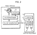
- external signal processing circuitry may be provided to which is input pulses from the speed/distance sender and pulses from the switches which indicate the instants at which the vehicle passes the starting and finishing markers.
- This external circuitry may include pulse counting means for counting the integral pulses between the starting and finishing markers; timing and or (fast) pulse counting means for timing the intervals between the starting marker and the first rising edge and between the last pulse and the finishing marker, and computational circuitry for calculating precisely the number of integral sender pulses and fractions of sender pulses for providing a calibration factor. This may be in the form of a readout which enables the tachograph calibration setting to be adjusted accordingly.
- the fractions of track length can simply be subtracted or added to the known track length when determining the distance covered by the vehicle during the interval of "x" full or integral pulses transmitted by (e.g.) the gearbox sender.
- the number "x” will vary according to the vehicle and pulse generator, and any variation in track length. It may be the number of pulses which fit into the distance between the markers, or the number which envelope this distance. Usually, a fraction of a sender pulse will occur after passing the starting marker, and another fraction will occur just before passing the finishing marker. This will become clearer when considering the exemplary embodiment described below.
- the fractions of track length could be used to determine corresponding fractions of sender pulses, which are then combined with the count of full sender pulses to provide a value that is equated with the known distance between the markers to determine a calibration factor for the speed/distance measuring device on the vehicle.
- the method could be put into effect by using a bar code and a bar code reader to determine the fractional track lengths.
- the vehicle can be fitted with a bar code extending in its normal direction of travel (this could be permanently fitted to the vehicle).
- a bar code reader is then provided at each marker position so as to scan the bar code as the vehicle passes by.
- the amount of bar code read before the first leading edge of the sender pulse occurs is proportional to a distance (or fraction of the track length) which needs to be deducted from the track length when determining the relationship between the sender pulse count and distance travelled.
- the on-board microprocessor in a tachograph could be used to calculate and to store a calibration factor for that vehicle.
- fractional track distances could be converted into fractional pulses at the starting and finishing markers to proceed as before.
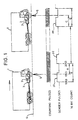
- a vehicle 1, having a sender pulse generating device 2 fitted to its gearbox 3, is shown at the start of a track 4, which has an accurately predetermined length (for example, 20 metres).
- the length of the track may be measured by any suitable accurate measuring means.
- markers 5 and 6 marks the start and the end of the measured track length. These markers are shown schematically, because they may, in fact, be some form of switch which is operated when a reference point on the vehicle 1 passes the respective marker 5 or 6.
- markers 5 and 6 may be V-blocks which are arranged at spaced intervals on the track, the edges of the V's accurately representing the start and finish of the measured portion of the track.
- An antenna or wand-shaped contact member, temporarily mounted on the vehicle may be arranged to strike the V's, one after the other, whereby switch contacts are closed causing signals to be generated which mark the start and finish of the "window" in which pulses, from sender pulse generating device 2, are counted. If the switch is fitted to the vehicle, this avoids the need for any trailing leads, since measurements can be made on board.
- switch may be used.
- an alternative mechanical switch may be a pressure strip (or mat) which is compressed by the vehicle tyre and thereby operates switch contacts.
- optical arrangements may be employed where, for example, a reference part of the vehicle intercepts a beam of radiation, at the marker, thereby causing a pulse to be generated.
- the marker may be a mirror for reflecting a beam of radiation, projected from the vehicle, whereby the reflected beam is detected by a photocell in order to provide a pulse signal.
- the nature of the switch is not important, as long as it provides an accurate indication of the entry of the vehicle onto the track (at the starting marker), and the exit of the vehicle (at the finishing marker).
- the signal processing means 7 which is used to count the integral number of pulses and to determine the fractions of a pulse length at the starting and finishing markers, may be incorporated in the microprocessor, or it may be external to the tachograph. In either case, a microprocessor may be used to control the signal processing so that the time intervals, which represent fractions of a pulse length at the starting and finishing markers, are determined and so that these intervals are combined with the integral number of pulses effectively to add both fractions to the pulse count and thus accurately determine how many pulses and what fraction of a pulse is generated when the vehicle travels, over the track, between the starting and finishing markers.
- the vehicle is preferably caused to travel over the measured length of the track at constant speed.
- the pulses generated by the sender pulse generator are counted within the window between the starting and finishing pulses.
- Fig. 1 shows a typical pulse diagram where a sender pulse p1 was started before the vehicle reached the starting marker, whereby only a fraction of the pulse occurs subsequently.
- the last pulse pf started just prior to reaching the finishing marker is incomplete as the vehicle passes this marker.
- square sender pulses are generated. The start of the sender pulse is a rising edge and the end of the pulse occurs coincidentally with the rising edge of the next sender pulse.
- a sender pulse length B With a sender pulse length B, only a fraction A of the pulse occurs after the vehicle passes the starting marker. At the end of the track, the sender pulse length D is the same as B (when the vehicle speed is constant over the track), but the fraction C of the last pulse occurs before the finishing marker.
- the times represented by A and C can be accurately measured. This can be achieved by generating pulses at a much faster rate than the sender pulses and by counting the number of fast or clock pulses which have been generated over intervals of interest. For example, the clock pulse count is stored on the occurrence of every rising edge of the sender pulse.
- the pulse count is 1053 on the rising edge which occurs just before the vehicle passes the starting marker 5.
- the clock pulse count (1353) is also stored when the vehicle passes the starting marker. This can be triggered by the switch which operates when an antenna, on the vehicle, strikes the V-block.
- the next clock pulse count to be stored (2053) is when the next rising edge of the sender pulse occurs.
- the ratio A/B is simply 700/1000 or 7/10 of a sender pulse length.
- a similar procedure is adopted at the finishing marker and this will be understood without any further detailed explanation.
- the number of full sender pulses occurring between the starting and finishing markers can be deduced from the number of pulse counts which represent the occurrence of rising edges after the vehicle has passed the starting marker and just before it passes the finishing marker.
- the time for one pulse length (B or D) is accurately known. Therefore, the ratios A/B and C/D represent the fractions of the pulses occurring at the start and the finish of the measured track. These are added to the integral number of pulses, which are counted over the measured track length, to give a nonintegral value of pulses generated over the measured track length. In the case of a 20 metre track, this figure could be multiplied by, for example, 50, to give the number of pulses per kilometre.
- a suitable fast or clock pulse may be generated by a oscillator which, by way of example only, produces a pulse every 10 microseconds. This can be part of the circuitry in the on-board microprocessor in a tachograph.
- the microprocessor can also cooperate with a counter (e.g. a 16 bit counter) which is incremented by each clock pulse, the clock pulse count being stored for every leading (or trailing) edge.
- the microprocessor on the vehicle calculates a calibration factor which it then store for use with that vehicle when subsequently converting the sender pulse rate into a speed indication and indexing an odometer which measures the distance covered by the vehicle.
- a bar code 15 is attached to the vehicle. There is only one bar code, but two are shown at the starting marker and two at the finishing marker to illustrate the positions of the bar code a times t1, t2 and t4, t5.
- a bar code reader 16 has its reading aperture aligned with starting marker 5
- another bar code reader 17 has its reading aperture aligned with the finishing marker 6.
- the leading edge of each sender pulse indexes a counter so as to count the number of full sender pulses which occur in the interval t5-t1, i.e. over the measured distance.
- both fractional track lengths need to deducted from the known track length before equating distance with the integral pulse count. It is also feasible for the fractional track lengths to be determined ahead of the starting marker and after the finishing marker, whereby both fractional track lengths are added to the known track length to determine a distance to be equated with an integral pulse count. In the latter cases, fractions of full or integral pulses extend beyond the markers and the pulse count is respectively different.
- a bar code is not essential, because other codes or grids of lines, or sequences of dots could provide similar information.
- a vehicle tester need only drive the vehicle over a short test track.
- the technique is accurate and it is also sufficient to calibrate a rolling road.
- the arrangement is applicable to all types of speed/distance senders which have an electronic output, including those which do not work at very low speeds.
- An onboard microprocessor can easily determine and store a calibration factor for the vehicle. This could also be easily changed or updated for the same vehicle (or a different vehicle if fitted with a replacement tachograph) to take account of e.g. gear box ratio, or tyre size, or axle ratio.
Landscapes
- Physics & Mathematics (AREA)
- General Physics & Mathematics (AREA)
- Radar Systems Or Details Thereof (AREA)
- Measurement Of Distances Traversed On The Ground (AREA)
- Control Of Transmission Device (AREA)
Priority Applications (1)
| Application Number | Priority Date | Filing Date | Title |
|---|---|---|---|
| SI9830366T SI1007979T1 (en) | 1997-08-29 | 1998-08-25 | A method for calibrating a speed or distance measuring device |
Applications Claiming Priority (3)
| Application Number | Priority Date | Filing Date | Title |
|---|---|---|---|
| GB9718379A GB2328749B (en) | 1997-08-29 | 1997-08-29 | A method for calibrating a speed or distance measuring device |
| GB9718379 | 1997-08-29 | ||
| PCT/GB1998/002551 WO1999012043A1 (en) | 1997-08-29 | 1998-08-25 | A method for calibrating a speed or distance measuring device |
Publications (2)
| Publication Number | Publication Date |
|---|---|
| EP1007979A1 EP1007979A1 (en) | 2000-06-14 |
| EP1007979B1 true EP1007979B1 (en) | 2002-12-18 |
Family
ID=10818258
Family Applications (1)
| Application Number | Title | Priority Date | Filing Date |
|---|---|---|---|
| EP98940379A Expired - Lifetime EP1007979B1 (en) | 1997-08-29 | 1998-08-25 | A method for calibrating a speed or distance measuring device |
Country Status (12)
| Country | Link |
|---|---|
| EP (1) | EP1007979B1 (da) |
| KR (1) | KR20010023415A (da) |
| AT (1) | ATE230117T1 (da) |
| AU (1) | AU8871798A (da) |
| BR (1) | BR9811400A (da) |
| DE (1) | DE69810310T2 (da) |
| DK (1) | DK1007979T3 (da) |
| ES (1) | ES2189222T3 (da) |
| GB (1) | GB2328749B (da) |
| PL (1) | PL188914B1 (da) |
| WO (1) | WO1999012043A1 (da) |
| ZA (1) | ZA987677B (da) |
Families Citing this family (7)
| Publication number | Priority date | Publication date | Assignee | Title |
|---|---|---|---|---|
| FR2812083B1 (fr) * | 2000-07-24 | 2003-01-17 | Marius Renoult | Simulateur et procede de simulation pour l'etalonnage et le controle de vehicules equipes d'un appareillage de mesure a indicateur de distance parcourue ou de vitesse |
| KR100456964B1 (ko) * | 2001-10-19 | 2004-11-10 | 기아자동차주식회사 | 차속신호 변환방법 |
| KR20040037591A (ko) * | 2002-10-29 | 2004-05-07 | 현대자동차주식회사 | 프로그램 가능한 차속 캘리브레이션 시스템 |
| DE102004047506B4 (de) * | 2004-09-28 | 2007-12-06 | Daimlerchrysler Ag | Verfahren und Vorrichtung zur bildgestützten Kalibrierung von Tachographen bei Fahrzeugen |
| FR2902515B1 (fr) * | 2006-06-15 | 2008-08-15 | Flip Technology Sa | Procede de determination d'un parametre relatif a la rotation d'un essieu de vehicule |
| FR2994594B1 (fr) * | 2012-08-16 | 2015-11-27 | Ct D Etudes Tech De L Equipement De L Ouest | Procede et systeme de mesure de la distance entre deux points d'un parcours |
| KR102494004B1 (ko) * | 2016-07-05 | 2023-01-31 | 현대자동차주식회사 | 차량용 제어 장치 및 그 제어 방법 |
Family Cites Families (9)
| Publication number | Priority date | Publication date | Assignee | Title |
|---|---|---|---|---|
| US3436656A (en) * | 1967-05-05 | 1969-04-01 | Gen Electric | Speed-measuring means with position-detector,error-eliminating means |
| FR2067770A5 (da) * | 1969-11-15 | 1971-08-20 | Nord Aviat | |
| JPS57144465A (en) * | 1981-02-28 | 1982-09-07 | Hitachi Ltd | Speed detecting method |
| US4352063A (en) * | 1981-05-08 | 1982-09-28 | Jones Peter W J | Self-calibrating speedometer/odometer |
| JPS58193468A (ja) * | 1982-04-22 | 1983-11-11 | Matsushita Electric Ind Co Ltd | 車輌用速度センサ−校正装置 |
| CH657916A5 (en) * | 1986-03-21 | 1986-09-30 | Gustav Friedrich Keyl | Electronic vehicle tachometer and method for calibrating it |
| GB2223588B (en) * | 1988-09-09 | 1992-01-29 | Westinghouse Brake & Signal | Wheel diameter calibration for a railway vehicle |
| US5323437A (en) * | 1992-09-16 | 1994-06-21 | Honeywell Inc. | Full and partial cycle counting apparatus and method |
| FR2739927B1 (fr) * | 1995-10-12 | 1997-11-28 | Muller Bem | Procede et dispositif de verification et/ou de controle d'appareils indicateurs ou enregistreurs de distance |
-
1997
- 1997-08-29 GB GB9718379A patent/GB2328749B/en not_active Expired - Fee Related
-
1998
- 1998-08-25 PL PL98338884A patent/PL188914B1/pl not_active IP Right Cessation
- 1998-08-25 BR BR9811400-0A patent/BR9811400A/pt not_active IP Right Cessation
- 1998-08-25 DK DK98940379T patent/DK1007979T3/da active
- 1998-08-25 ZA ZA9807677A patent/ZA987677B/xx unknown
- 1998-08-25 KR KR1020007002057A patent/KR20010023415A/ko not_active Ceased
- 1998-08-25 WO PCT/GB1998/002551 patent/WO1999012043A1/en not_active Ceased
- 1998-08-25 AU AU88717/98A patent/AU8871798A/en not_active Abandoned
- 1998-08-25 DE DE69810310T patent/DE69810310T2/de not_active Expired - Fee Related
- 1998-08-25 ES ES98940379T patent/ES2189222T3/es not_active Expired - Lifetime
- 1998-08-25 EP EP98940379A patent/EP1007979B1/en not_active Expired - Lifetime
- 1998-08-25 AT AT98940379T patent/ATE230117T1/de not_active IP Right Cessation
Also Published As
| Publication number | Publication date |
|---|---|
| GB2328749B (en) | 2001-05-09 |
| ES2189222T3 (es) | 2003-07-01 |
| EP1007979A1 (en) | 2000-06-14 |
| ZA987677B (en) | 2000-02-25 |
| ATE230117T1 (de) | 2003-01-15 |
| BR9811400A (pt) | 2000-08-29 |
| GB2328749A (en) | 1999-03-03 |
| DK1007979T3 (da) | 2003-04-14 |
| GB9718379D0 (en) | 1997-11-05 |
| DE69810310D1 (de) | 2003-01-30 |
| DE69810310T2 (de) | 2003-10-16 |
| WO1999012043A1 (en) | 1999-03-11 |
| PL188914B1 (pl) | 2005-05-31 |
| AU8871798A (en) | 1999-03-22 |
| PL338884A1 (en) | 2000-11-20 |
| KR20010023415A (ko) | 2001-03-26 |
Similar Documents
| Publication | Publication Date | Title |
|---|---|---|
| DE69719148T2 (de) | Positionsgeber, kodierungsplatte, verfahren zur positionserfassung, zeitgeber und elektronisches gerät | |
| US3982105A (en) | Device for the automatic reading and evaluation of recorded curves | |
| EP0352260B1 (en) | Method for storing run data of a vehicule in the memory of an electronic tachograph and apparatus for carrying out the method | |
| US4717915A (en) | Method and apparatus for the graphic registration of moving vehicles | |
| US4151969A (en) | System for selectively determining the location of a railway car moving along a railway track | |
| US3864731A (en) | Vehicle data recorder employing data compression | |
| EP1007979B1 (en) | A method for calibrating a speed or distance measuring device | |
| DE69004959T2 (de) | Verfahren zur eichung von fahrzeuggeschwindigkeitssignalen. | |
| US6446018B1 (en) | Method for compensating variations of a wheel speed sensor | |
| WO1985002675A1 (en) | Apparatus for measuring the lateral inclination of a supporting surface by means of a vehicle drivable thereon | |
| US4503374A (en) | Speed detection apparatus and method | |
| EP0068704B1 (en) | Speed meter systems | |
| DE2253485C3 (de) | Verfahren und Vorrichtung zur digitalen Messung des von einem Fahrzeug zurückgelegten Wegs | |
| SU1768430A1 (en) | Device for determining train movement parameters | |
| CZ2000746A3 (cs) | Způsob kalibrování zanzení pro měření rychlosti nebo vzdálenosti | |
| US4384339A (en) | Strip material area-meter | |
| US4389653A (en) | Line recording device | |
| US3728734A (en) | Method of resolving multiple sweep ambiguities encountered in high resolution graphic recorders and the like | |
| SU1283659A1 (ru) | Устройство дл измерени параметров движени локомотива | |
| SU931515A1 (ru) | Устройство дл измерени скорости движени локомотива | |
| SU1079521A1 (ru) | Устройство дл измерени пути,пройденного подвижной единицей | |
| SU1082552A1 (ru) | Устройство автоматического управлени порезом слитка | |
| SU1742619A1 (ru) | Устройство дл контрол окружного шага зубчатых колес | |
| SU1661019A1 (ru) | Устройство дл управлени торможением поезда | |
| SU1495173A1 (ru) | Устройство дл контрол путевых параметров транспортного средства |
Legal Events
| Date | Code | Title | Description |
|---|---|---|---|
| PUAI | Public reference made under article 153(3) epc to a published international application that has entered the european phase |
Free format text: ORIGINAL CODE: 0009012 |
|
| 17P | Request for examination filed |
Effective date: 20000307 |
|
| AK | Designated contracting states |
Kind code of ref document: A1 Designated state(s): AT BE CH CY DE DK ES FI FR GR IE IT LI LU MC NL PT SE |
|
| AX | Request for extension of the european patent |
Free format text: SI PAYMENT 20000307 |
|
| GRAG | Despatch of communication of intention to grant |
Free format text: ORIGINAL CODE: EPIDOS AGRA |
|
| 17Q | First examination report despatched |
Effective date: 20011016 |
|
| RBV | Designated contracting states (corrected) |
Designated state(s): AT BE CH CY DE DK ES FI FR GR IE IT LI LU MC NL PT SE |
|
| RAP1 | Party data changed (applicant data changed or rights of an application transferred) |
Owner name: STONERIDGE CONTROL DEVICES INC. |
|
| GRAG | Despatch of communication of intention to grant |
Free format text: ORIGINAL CODE: EPIDOS AGRA |
|
| GRAH | Despatch of communication of intention to grant a patent |
Free format text: ORIGINAL CODE: EPIDOS IGRA |
|
| RAP1 | Party data changed (applicant data changed or rights of an application transferred) |
Owner name: STONERIDGE ELECTRONICS LIMITED |
|
| GRAH | Despatch of communication of intention to grant a patent |
Free format text: ORIGINAL CODE: EPIDOS IGRA |
|
| GRAA | (expected) grant |
Free format text: ORIGINAL CODE: 0009210 |
|
| AK | Designated contracting states |
Kind code of ref document: B1 Designated state(s): AT BE CH CY DE DK ES FI FR GR IE IT LI LU MC NL PT SE |
|
| AX | Request for extension of the european patent |
Free format text: SI PAYMENT 20000307 |
|
| REF | Corresponds to: |
Ref document number: 230117 Country of ref document: AT Date of ref document: 20030115 Kind code of ref document: T |
|
| REG | Reference to a national code |
Ref country code: CH Ref legal event code: EP |
|
| REG | Reference to a national code |
Ref country code: IE Ref legal event code: FG4D |
|
| REF | Corresponds to: |
Ref document number: 69810310 Date of ref document: 20030130 Kind code of ref document: P Country of ref document: DE |
|
| REG | Reference to a national code |
Ref country code: SE Ref legal event code: TRGR |
|
| REG | Reference to a national code |
Ref country code: DK Ref legal event code: T3 |
|
| REG | Reference to a national code |
Ref country code: GR Ref legal event code: EP Ref document number: 20030401003 Country of ref document: GR |
|
| REG | Reference to a national code |
Ref country code: ES Ref legal event code: FG2A Ref document number: 2189222 Country of ref document: ES Kind code of ref document: T3 |
|
| REG | Reference to a national code |
Ref country code: CH Ref legal event code: NV Representative=s name: PATENTANWAELTE SCHAAD, BALASS, MENZL & PARTNER AG |
|
| ET | Fr: translation filed | ||
| PLBE | No opposition filed within time limit |
Free format text: ORIGINAL CODE: 0009261 |
|
| STAA | Information on the status of an ep patent application or granted ep patent |
Free format text: STATUS: NO OPPOSITION FILED WITHIN TIME LIMIT |
|
| 26N | No opposition filed |
Effective date: 20030919 |
|
| PGFP | Annual fee paid to national office [announced via postgrant information from national office to epo] |
Ref country code: CY Payment date: 20040720 Year of fee payment: 7 |
|
| PGFP | Annual fee paid to national office [announced via postgrant information from national office to epo] |
Ref country code: MC Payment date: 20040728 Year of fee payment: 7 |
|
| PGFP | Annual fee paid to national office [announced via postgrant information from national office to epo] |
Ref country code: NL Payment date: 20040803 Year of fee payment: 7 |
|
| PGFP | Annual fee paid to national office [announced via postgrant information from national office to epo] |
Ref country code: SE Payment date: 20040806 Year of fee payment: 7 |
|
| PGFP | Annual fee paid to national office [announced via postgrant information from national office to epo] |
Ref country code: FR Payment date: 20040810 Year of fee payment: 7 |
|
| PGFP | Annual fee paid to national office [announced via postgrant information from national office to epo] |
Ref country code: IE Payment date: 20040811 Year of fee payment: 7 Ref country code: AT Payment date: 20040811 Year of fee payment: 7 |
|
| PGFP | Annual fee paid to national office [announced via postgrant information from national office to epo] |
Ref country code: FI Payment date: 20040812 Year of fee payment: 7 |
|
| PGFP | Annual fee paid to national office [announced via postgrant information from national office to epo] |
Ref country code: DK Payment date: 20040813 Year of fee payment: 7 |
|
| PGFP | Annual fee paid to national office [announced via postgrant information from national office to epo] |
Ref country code: PT Payment date: 20040823 Year of fee payment: 7 |
|
| PGFP | Annual fee paid to national office [announced via postgrant information from national office to epo] |
Ref country code: ES Payment date: 20040825 Year of fee payment: 7 |
|
| PGFP | Annual fee paid to national office [announced via postgrant information from national office to epo] |
Ref country code: LU Payment date: 20040826 Year of fee payment: 7 |
|
| PGFP | Annual fee paid to national office [announced via postgrant information from national office to epo] |
Ref country code: GR Payment date: 20040827 Year of fee payment: 7 Ref country code: CH Payment date: 20040827 Year of fee payment: 7 |
|
| PGFP | Annual fee paid to national office [announced via postgrant information from national office to epo] |
Ref country code: DE Payment date: 20040902 Year of fee payment: 7 |
|
| PGFP | Annual fee paid to national office [announced via postgrant information from national office to epo] |
Ref country code: BE Payment date: 20041021 Year of fee payment: 7 |
|
| REG | Reference to a national code |
Ref country code: SI Ref legal event code: IF |
|
| PG25 | Lapsed in a contracting state [announced via postgrant information from national office to epo] |
Ref country code: LU Free format text: LAPSE BECAUSE OF NON-PAYMENT OF DUE FEES Effective date: 20050825 Ref country code: IT Free format text: LAPSE BECAUSE OF NON-PAYMENT OF DUE FEES Effective date: 20050825 Ref country code: IE Free format text: LAPSE BECAUSE OF NON-PAYMENT OF DUE FEES Effective date: 20050825 Ref country code: FI Free format text: LAPSE BECAUSE OF NON-PAYMENT OF DUE FEES Effective date: 20050825 Ref country code: AT Free format text: LAPSE BECAUSE OF NON-PAYMENT OF DUE FEES Effective date: 20050825 |
|
| PG25 | Lapsed in a contracting state [announced via postgrant information from national office to epo] |
Ref country code: SE Free format text: LAPSE BECAUSE OF NON-PAYMENT OF DUE FEES Effective date: 20050826 Ref country code: ES Free format text: LAPSE BECAUSE OF NON-PAYMENT OF DUE FEES Effective date: 20050826 |
|
| PG25 | Lapsed in a contracting state [announced via postgrant information from national office to epo] |
Ref country code: MC Free format text: LAPSE BECAUSE OF NON-PAYMENT OF DUE FEES Effective date: 20050831 Ref country code: LI Free format text: LAPSE BECAUSE OF NON-PAYMENT OF DUE FEES Effective date: 20050831 Ref country code: DK Free format text: LAPSE BECAUSE OF NON-PAYMENT OF DUE FEES Effective date: 20050831 Ref country code: CH Free format text: LAPSE BECAUSE OF NON-PAYMENT OF DUE FEES Effective date: 20050831 Ref country code: BE Free format text: LAPSE BECAUSE OF NON-PAYMENT OF DUE FEES Effective date: 20050831 |
|
| PG25 | Lapsed in a contracting state [announced via postgrant information from national office to epo] |
Ref country code: PT Free format text: LAPSE BECAUSE OF NON-PAYMENT OF DUE FEES Effective date: 20060227 |
|
| PG25 | Lapsed in a contracting state [announced via postgrant information from national office to epo] |
Ref country code: NL Free format text: LAPSE BECAUSE OF NON-PAYMENT OF DUE FEES Effective date: 20060301 Ref country code: DE Free format text: LAPSE BECAUSE OF NON-PAYMENT OF DUE FEES Effective date: 20060301 |
|
| PG25 | Lapsed in a contracting state [announced via postgrant information from national office to epo] |
Ref country code: GR Free format text: LAPSE BECAUSE OF NON-PAYMENT OF DUE FEES Effective date: 20060302 |
|
| REG | Reference to a national code |
Ref country code: CH Ref legal event code: PL |
|
| REG | Reference to a national code |
Ref country code: DK Ref legal event code: EBP |
|
| EUG | Se: european patent has lapsed | ||
| PG25 | Lapsed in a contracting state [announced via postgrant information from national office to epo] |
Ref country code: FR Free format text: LAPSE BECAUSE OF NON-PAYMENT OF DUE FEES Effective date: 20060428 |
|
| NLV4 | Nl: lapsed or anulled due to non-payment of the annual fee |
Effective date: 20060301 |
|
| REG | Reference to a national code |
Ref country code: IE Ref legal event code: MM4A |
|
| REG | Reference to a national code |
Ref country code: FR Ref legal event code: ST Effective date: 20060428 |
|
| REG | Reference to a national code |
Ref country code: SI Ref legal event code: KO00 Effective date: 20060413 |
|
| REG | Reference to a national code |
Ref country code: ES Ref legal event code: FD2A Effective date: 20050826 |
|
| BERE | Be: lapsed |
Owner name: *STONERIDGE ELECTRONICS LTD Effective date: 20050831 |