EP1007475B1 - Filtersystem für reaktor zur umsetzung von uf6 in uranoxid - Google Patents
Filtersystem für reaktor zur umsetzung von uf6 in uranoxid Download PDFInfo
- Publication number
- EP1007475B1 EP1007475B1 EP99920881A EP99920881A EP1007475B1 EP 1007475 B1 EP1007475 B1 EP 1007475B1 EP 99920881 A EP99920881 A EP 99920881A EP 99920881 A EP99920881 A EP 99920881A EP 1007475 B1 EP1007475 B1 EP 1007475B1
- Authority
- EP
- European Patent Office
- Prior art keywords
- filtration
- sector
- uranium
- reaction gases
- pressure
- Prior art date
- Legal status (The legal status is an assumption and is not a legal conclusion. Google has not performed a legal analysis and makes no representation as to the accuracy of the status listed.)
- Expired - Lifetime
Links
- 238000001914 filtration Methods 0.000 title claims description 62
- WZECUPJJEIXUKY-UHFFFAOYSA-N [O-2].[O-2].[O-2].[U+6] Chemical compound [O-2].[O-2].[O-2].[U+6] WZECUPJJEIXUKY-UHFFFAOYSA-N 0.000 title claims description 9
- 229910000439 uranium oxide Inorganic materials 0.000 title claims description 9
- 239000007789 gas Substances 0.000 claims description 26
- 238000006243 chemical reaction Methods 0.000 claims description 22
- SANRKQGLYCLAFE-UHFFFAOYSA-H uranium hexafluoride Chemical compound F[U](F)(F)(F)(F)F SANRKQGLYCLAFE-UHFFFAOYSA-H 0.000 claims description 9
- 150000001875 compounds Chemical class 0.000 claims description 7
- 239000000843 powder Substances 0.000 claims description 6
- 230000007547 defect Effects 0.000 claims description 2
- 230000000717 retained effect Effects 0.000 claims description 2
- 238000007664 blowing Methods 0.000 claims 1
- 238000000034 method Methods 0.000 description 8
- 230000008569 process Effects 0.000 description 6
- XLYOFNOQVPJJNP-UHFFFAOYSA-N water Substances O XLYOFNOQVPJJNP-UHFFFAOYSA-N 0.000 description 5
- IJGRMHOSHXDMSA-UHFFFAOYSA-N Atomic nitrogen Chemical compound N#N IJGRMHOSHXDMSA-UHFFFAOYSA-N 0.000 description 4
- 238000004519 manufacturing process Methods 0.000 description 4
- 229910052770 Uranium Inorganic materials 0.000 description 3
- 239000000443 aerosol Substances 0.000 description 3
- 230000007257 malfunction Effects 0.000 description 3
- 230000009467 reduction Effects 0.000 description 3
- DNYWZCXLKNTFFI-UHFFFAOYSA-N uranium Chemical compound [U][U][U][U][U][U][U][U][U][U][U][U][U][U][U][U][U][U][U][U][U][U][U][U][U][U][U][U][U][U][U][U][U][U][U][U][U][U][U][U][U][U][U][U][U][U][U][U][U][U][U][U][U][U][U][U][U][U][U][U][U][U][U][U][U][U][U][U][U][U][U][U][U][U][U][U][U][U][U][U][U][U][U][U][U][U][U][U][U][U][U][U][U][U][U][U][U][U][U][U][U][U][U][U][U][U][U][U][U][U][U][U][U][U] DNYWZCXLKNTFFI-UHFFFAOYSA-N 0.000 description 3
- QGZKDVFQNNGYKY-UHFFFAOYSA-N Ammonia Chemical compound N QGZKDVFQNNGYKY-UHFFFAOYSA-N 0.000 description 2
- 230000009471 action Effects 0.000 description 2
- 230000008901 benefit Effects 0.000 description 2
- 238000009530 blood pressure measurement Methods 0.000 description 2
- 229910052739 hydrogen Inorganic materials 0.000 description 2
- 230000007062 hydrolysis Effects 0.000 description 2
- 238000006460 hydrolysis reaction Methods 0.000 description 2
- 229910052757 nitrogen Inorganic materials 0.000 description 2
- OOAWCECZEHPMBX-UHFFFAOYSA-N oxygen(2-);uranium(4+) Chemical compound [O-2].[O-2].[U+4] OOAWCECZEHPMBX-UHFFFAOYSA-N 0.000 description 2
- 239000002245 particle Substances 0.000 description 2
- 238000000197 pyrolysis Methods 0.000 description 2
- FCTBKIHDJGHPPO-UHFFFAOYSA-N uranium dioxide Inorganic materials O=[U]=O FCTBKIHDJGHPPO-UHFFFAOYSA-N 0.000 description 2
- UFHFLCQGNIYNRP-UHFFFAOYSA-N Hydrogen Chemical compound [H][H] UFHFLCQGNIYNRP-UHFFFAOYSA-N 0.000 description 1
- 229910021529 ammonia Inorganic materials 0.000 description 1
- 238000004140 cleaning Methods 0.000 description 1
- 238000001816 cooling Methods 0.000 description 1
- 238000007865 diluting Methods 0.000 description 1
- 230000002349 favourable effect Effects 0.000 description 1
- 230000005484 gravity Effects 0.000 description 1
- 238000010438 heat treatment Methods 0.000 description 1
- 239000001257 hydrogen Substances 0.000 description 1
- 238000002347 injection Methods 0.000 description 1
- 239000007924 injection Substances 0.000 description 1
- 238000005372 isotope separation Methods 0.000 description 1
- 229910052751 metal Inorganic materials 0.000 description 1
- 239000002184 metal Substances 0.000 description 1
- 230000007935 neutral effect Effects 0.000 description 1
- 230000000704 physical effect Effects 0.000 description 1
- 239000012495 reaction gas Substances 0.000 description 1
- 238000005245 sintering Methods 0.000 description 1
- 230000008646 thermal stress Effects 0.000 description 1
- 230000032258 transport Effects 0.000 description 1
Images
Classifications
-
- C—CHEMISTRY; METALLURGY
- C01—INORGANIC CHEMISTRY
- C01G—COMPOUNDS CONTAINING METALS NOT COVERED BY SUBCLASSES C01D OR C01F
- C01G43/00—Compounds of uranium
- C01G43/01—Oxides; Hydroxides
- C01G43/025—Uranium dioxide
-
- B—PERFORMING OPERATIONS; TRANSPORTING
- B01—PHYSICAL OR CHEMICAL PROCESSES OR APPARATUS IN GENERAL
- B01D—SEPARATION
- B01D46/00—Filters or filtering processes specially modified for separating dispersed particles from gases or vapours
Definitions
- the present invention relates to the filtration of reaction gases from a fluidized bed reactor for the conversion of uranium hexafluoride UF 6 to uranium oxide, in particular to UO 2 oxide.
- Enriched uranium from isotope separation plants is generally in the form of UF 6 hexafluoride. This hexafluoride must generally be transformed into oxide powder UO 2 which, to be sinterable, must have a certain number of physical properties. There are various methods for obtaining quality uranium dioxide UO 2 suitable for sintering from hexafluoride.
- An interesting conversion process consists in passing through the intermediate compound UO 2 F 2 .
- the hexafluoride is transformed into oxyfluoride at the end of the following reaction: UF 6 + 2H 2 O ⁇ UO 2 F 2 + 4HF the water being supplied in the form of vapor.
- Extremely reactive oxyfluoride can be obtained by very diluting the water vapor with air or nitrogen.
- UO 2 oxide is obtained at the end of the second phase of the process, by the following reaction: UO 2 F 2 + H 2 ⁇ UO 2 + 2HF
- a reducing hydrolysis of UO 2 F 2 can be carried out by steam in the presence of hydrogen which can be supplied by cracked ammonia.
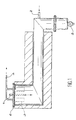
- Document FR-A-2 060 242 discloses a process for the manufacture of sinterable uranium oxide from uranium hexafluoride that we do react uranium hexafluoride gas with water vapor at a temperature above 100 ° C, immediately subtracts the oxyfluoride from the reaction to the action of hexafluoride and we transform oxyfluoride to uranium oxide. This process can be implemented in the device represented in the figure 1 attached.
- the device shown diagrammatically in FIG. 1 consists of an oven, the enclosure of which has an S-shape.
- the products of the reaction pass successively through the oven through several zones brought to different temperatures and adjustable by means of heating, not shown.
- the UF 6 as well as the water vapor and the nitrogen, depending on whether it is operating cocurrently or countercurrently, are introduced through a gas filtration chamber at the upper left of the oven by a pipe fitted with an injector 1.
- a pipe 2 is used for the introduction of pyrolysis gases and reduction of UO 2 F 2 (pure or diluted water vapor).
- the gases from the reaction leave the oven enclosure through sintered metal filters 3, with automatic unclogging, which avoid the entrainment of UO 2 F 2 in line 4 and retain the particles entrained by the pyrolysis gases.
- the filters 3 are supported by a closing element 6 in the upper part of the oven, this element being traversed by the duct 1.
- the hexafluoride UF 6 being transformed into UO 2 F 2 from the left part of the oven, maintained at a temperature of the order of 180 ° C, UO 2 F 2 is very quickly removed from the action of UF 6 .
- the powder UO 2 F 2 is then transformed into oxide in the part shown horizontally in Figure 1, where it is driven by conventional means, which can be added to gravity if a sufficient slope is provided.
- the powdered uranium oxide is finally extracted by a rotary valve or an endless screw 5. Thanks to the above arrangement, the residence time of UO 2 F 2 in the hydrolysis zone is very short, neighbor of the second in general.
- Filters can consist of filter candles distributed in several sectors. he for example there may be eight sectors with each seventeen candles, which allows to have six sectors in operation, a sector of which the candles are being unclogged and a sector waiting for unclogging.
- the candles constituting the filters are subjected to relatively high thermal stresses. Given their number (136 in the example given above), there is the risk that one of them breaks or deteriorates and that oxyfluoride passes through line 4. It is important to be able to detect quickly a leak of UO 2 F 2 .
- UO 2 F 2 is in the form of a very fine powder and therefore occurs in the form of an aerosol in the gas flow. Aerosol particles are usually electrically charged and can be collected by an electrostatic filtration method. However, it turns out that UO 2 F 2 constitutes an uncharged aerosol. Other methods of recovering this product from a gas stream can be envisaged, for example by mechanical filtration, but they have not been found to be satisfactory.
- Document US-A-4,053,559 discloses a process for the manufacture of uranium dioxide powder from UF 6 in a series of four fluidized bed reactors.
- the fourth reactor notably comprises internal filters for the reaction gases, these internal filters being with automatic unclogging. Other filtration means are also provided downstream of these internal filters.
- a filtration system including a first unclogging filtration stage and a second non-cleanable filtration stage allowing to detect, by pressure measurement, the faults on the first floor and thus playing the role of guard filter.
- the subject of the invention is therefore a reaction gas filtration system originating from a fluidized bed reactor for the conversion of uranium hexafluoride UF 6 to uranium oxide, comprising first filtration means, with automatic unclogging. , allowing said reaction gases to pass and retaining the pulverulent intermediate compound UO 2 F 2 which forms during the conversion, second filtration means being provided downstream of the first filtration means for letting said reaction gases pass and for retaining the compound UO 2 F 2 in the event of a leak due to a malfunction of the first filtration means, characterized in that the second filtration means cannot be unclogged automatically, said first filtration means being distributed in several sectors, the second filtration means also being divided into several sectors, to each sector of the first filtration means corresponding a sector of es second filtration means, the system further comprising means for controlling the presence of the compound UO 2 F 2 retained in the second filtration means, these control means comprising means for measuring pressure.
- the control means can thus compare the pressure inside the reactor and the
- the first and second means of filtration can consist of candles filter.
- the invention further provides the advantage a favorable geometric arrangement for the primary filtration, which provides a preliminary cooling of the gases to be filtered therefore a substantial reduction in the volume of gas to be filtered and as a result a reduction in the area of filtration.
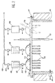
- FIG. 2 top of the oven corresponding to the left side of Figure 1, i.e. the one with the system filtration according to the invention.
- the closure element 11 is pierced with eight holes for the establishment of a first floor of filtration with eight sectors 13.
- Each sector 13 is made up of a plate 14 tightly fixed on the element of closing 11 and supporting seventeen filter candles 15, with automatic unclogging, the heads of which are also fixed in a sealed manner on the plate 14.
- the plate 14 is surmounted by a bell 16 serving as collector of filtered gases.
- Each bell 16 is connected to a pipe 17 for recovering the filtered gases which transports these to a second floor of filtration.
- the second filtration stage includes as many sectors as the first filtration stage. Each sector 18 of the second floor has three candles. These candles are not unclogged or less there is no system to allow them unclog.
- each sector 18 of the second filtration stage is connected to a conduit 19 which joins the general evacuation pipe.
- the filter plugs 15 of the first filtration stage allow the reaction gases to be recovered to pass and retain UO 2 F 2 which is deposited on the surface of the plugs in contact with the atmosphere of the furnace.
- the filtered gases then pass the second filtration stage to be recovered and treated.
- the filter candles from first stage of filtration are unclogged. Their cleaning is for example carried out by injection pulsating of a neutral gas under pressure inside candles.
- oxyfluoride passes in sector 18 of second corresponding filtration stage.
- the three candles from this sector end up clogging up but the oxyfluoride does not pass.
- Detectors pressure can be safely arranged on the reactor and its filtration system.
- a detector pressure 21 is for example installed on the part top of the oven 10.
- the outlet of each sector 13 of the first filtration stage can be equipped with a pressure detector 22.
- the outlet of each sector 18 of the second filtration stage can be fitted a pressure detector 23.
- the pressure in the reactor can be 1050 mbar absolute
- the intermediate pressure between the two stages of filtration can be 900 mbar absolute
- the gas outlet pressure (in line 19) can be 700 to 800 mbar absolute.
- a malfunction can then be detected if the intermediate pressure between a sector of the first filtration stage and the corresponding sector of the second filtration stage becomes equal to the reactor pressure.
Landscapes
- Chemical & Material Sciences (AREA)
- Organic Chemistry (AREA)
- Life Sciences & Earth Sciences (AREA)
- General Life Sciences & Earth Sciences (AREA)
- Geology (AREA)
- Inorganic Chemistry (AREA)
- Chemical Kinetics & Catalysis (AREA)
- Inorganic Compounds Of Heavy Metals (AREA)
- Devices And Processes Conducted In The Presence Of Fluids And Solid Particles (AREA)
Claims (4)
- System zum Filtern von Reaktionsgas, das aus einem Wirbelschichtreaktor (10) zur Umwandlung von Uranhexafluorid UF6 in Uranoxid herrührt, umfassend erste Filtermittel (13) mit automatischer Durchspülung, welche die Reaktionsgase passieren lassen und die pulverige Zwischenverbindung UO2F2, die sich während der Umwandlung bildet, zurückhalten, zweite Filtermittel (18), welche stromab der ersten Filtermittel (13) vorgesehen sind, um die Reaktionsgase passieren zu lassen und die Verbindung UO2F2 im Fall eines Lecks infolge eines Funktionsfehlers der ersten Filtermittel (13) zurückzuhalten, dadurch gekennzeichnet, daß die zweiten Filtermittel (18) nicht automatisch durchspülbar sind, wobei die ersten Filtermittel auf mehrere Sektoren (13) aufgeteilt sind, die zweiten Filtermittel ebenfalls auf mehrere Sektoren (18) aufgeteilt sind, wobei jedem Sektor (13) der ersten Filtermittel ein Sektor (18) der zweiten Filtermittel entspricht, und das System außerdem Mittel zur Überwachung des Vorhandenseins der in den zweiten Filtermitteln (18) zurückgehaltenen Verbindung UO2F2 aufweist, und die Überwachungsmittel Mittel zum Messen des Drucks (21,22) umfassen.
- Filtersystem nach Anspruch 1, dadurch gekennzeichnet, daß die Überwachungsmittel den Druck im Innern des Reaktors und den Druck der Reaktionsgase zwischen den ersten (13) und den zweiten Filtermitteln vergleichen.
- Filtersystem nach einem der Ansprüche 1 oder 2, dadurch gekennzeichnet, daß die ersten Filtermittel aus Filtrierkerzen (15) bestehen.
- Filtersystem nach einem der Ansprüche 1 bis 3, dadurch gekennzeichnet, daß die zweiten Filtermittel aus Filtrierkerzen bestehen.
Applications Claiming Priority (3)
| Application Number | Priority Date | Filing Date | Title |
|---|---|---|---|
| FR9806303A FR2778908B1 (fr) | 1998-05-19 | 1998-05-19 | Systeme de filtration pour reacteur de conversion d'uf6 en oxyde d'uranium |
| FR9806303 | 1998-05-19 | ||
| PCT/FR1999/001178 WO1999059920A1 (fr) | 1998-05-19 | 1999-05-18 | Systeme de filtration pour reacteur de conversion d'uf6 en oxyde d'uranium |
Publications (2)
| Publication Number | Publication Date |
|---|---|
| EP1007475A1 EP1007475A1 (de) | 2000-06-14 |
| EP1007475B1 true EP1007475B1 (de) | 2002-08-21 |
Family
ID=9526495
Family Applications (1)
| Application Number | Title | Priority Date | Filing Date |
|---|---|---|---|
| EP99920881A Expired - Lifetime EP1007475B1 (de) | 1998-05-19 | 1999-05-18 | Filtersystem für reaktor zur umsetzung von uf6 in uranoxid |
Country Status (7)
| Country | Link |
|---|---|
| EP (1) | EP1007475B1 (de) |
| JP (1) | JP4477775B2 (de) |
| CA (1) | CA2296745C (de) |
| DE (1) | DE69902571T2 (de) |
| FR (1) | FR2778908B1 (de) |
| RU (1) | RU2232131C2 (de) |
| WO (1) | WO1999059920A1 (de) |
Families Citing this family (3)
| Publication number | Priority date | Publication date | Assignee | Title |
|---|---|---|---|---|
| RU2381993C2 (ru) * | 2008-01-16 | 2010-02-20 | Открытое акционерное общество "Машиностроительный завод" | Способ получения порошка диоксида урана методом пирогидролиза и установка для его осуществления |
| RU2498941C2 (ru) * | 2012-02-28 | 2013-11-20 | Открытое акционерное общество "Машиностроительный завод" | Реакционная камера для получения порошка диоксида урана методом пирогидролиза из гексафторида урана (варианты) |
| ES2980425T3 (es) | 2018-10-09 | 2024-10-01 | Framatome Sa | Procedimiento e instalación de conversión de hexafluoruro de uranio en dióxido de uranio |
Family Cites Families (5)
| Publication number | Priority date | Publication date | Assignee | Title |
|---|---|---|---|---|
| SU437519A1 (ru) * | 1971-07-22 | 1974-07-30 | Предприятие П/Я М-5641 | Фильтр дл очистки воздуха |
| SU494181A1 (ru) * | 1974-06-03 | 1975-12-05 | Центральный научно-исследовательский и проектно-экспериментальный институт промышленных зданий и сооружений | Устройство дл автоматического управлени работой рулонного фильтра |
| US4053559A (en) * | 1976-06-14 | 1977-10-11 | Westinghouse Electric Corporation | Production of uranium dioxide |
| US4830841A (en) * | 1984-12-24 | 1989-05-16 | Advanced Nuclear Fuels Corporation | Conversion of uranium hexafluoride to uranium dioxide |
| GB9411096D0 (en) * | 1994-06-03 | 1994-07-27 | British Nuclear Fuels Plc | Uranium oxide production |
-
1998
- 1998-05-19 FR FR9806303A patent/FR2778908B1/fr not_active Expired - Lifetime
-
1999
- 1999-05-18 RU RU2000104162/15A patent/RU2232131C2/ru active
- 1999-05-18 JP JP2000549543A patent/JP4477775B2/ja not_active Expired - Lifetime
- 1999-05-18 DE DE69902571T patent/DE69902571T2/de not_active Expired - Lifetime
- 1999-05-18 WO PCT/FR1999/001178 patent/WO1999059920A1/fr not_active Ceased
- 1999-05-18 CA CA002296745A patent/CA2296745C/fr not_active Expired - Lifetime
- 1999-05-18 EP EP99920881A patent/EP1007475B1/de not_active Expired - Lifetime
Also Published As
| Publication number | Publication date |
|---|---|
| DE69902571T2 (de) | 2003-04-10 |
| CA2296745C (fr) | 2008-12-30 |
| FR2778908B1 (fr) | 2000-06-30 |
| JP2002515395A (ja) | 2002-05-28 |
| JP4477775B2 (ja) | 2010-06-09 |
| RU2232131C2 (ru) | 2004-07-10 |
| WO1999059920A1 (fr) | 1999-11-25 |
| DE69902571D1 (de) | 2002-09-26 |
| EP1007475A1 (de) | 2000-06-14 |
| CA2296745A1 (fr) | 1999-11-25 |
| FR2778908A1 (fr) | 1999-11-26 |
Similar Documents
| Publication | Publication Date | Title |
|---|---|---|
| EP0960070B1 (de) | Verfahren und vorrichtung zur direkten umsetzung von uranhexafluorid in uranoxid | |
| EP0032341B1 (de) | Vorrichtung zum Zerstäuben einer reaktionsfähigen Mischung | |
| US6905533B2 (en) | Filtering and inerting of combustible dusts in the process off-gas | |
| JPH02280808A (ja) | 液状灰を分離する方法及び装置 | |
| WO2002078818A3 (en) | Acceleration assisted particle/gas separation system | |
| JP5761932B2 (ja) | フィルタ装置の再生方法及びフィルタ装置の再生システム | |
| EP1219336B1 (de) | Verfahren und Vorrichtung zur Entfernung von schädlichen flüchtigen Verbindungen, insbesondere Sulfaten und/oder Chloriden, aus einem Rauchgasstrom | |
| CN102239016A (zh) | 用于废弃物材料处理的等离子体法及其设备 | |
| EP1007475B1 (de) | Filtersystem für reaktor zur umsetzung von uf6 in uranoxid | |
| EP0095802B1 (de) | Geräte zur Entnahme von Gasproben | |
| EP0873784B1 (de) | Verfahren und Gehäuse für die Regenerierung eines Katalysators mit Kontrolle des Endes des Verbrennungsprozesses | |
| EP1521731B1 (de) | Verfahren und vorrichtung zur herstellung von kohlenstoffprodukten aus kohlenstoffvorläuferprodukten | |
| JPH04265426A (ja) | ガスを使用する装置及びその損傷を防止する方法 | |
| CN104291284B (zh) | 一种超纯氩气在线净化系统及方法 | |
| FR2596907A1 (fr) | Procede et dispositif de traitement de fluides contenant en suspension des particules | |
| FR3037331A1 (fr) | Installation, procede de denitration thermique, utilisation d'une telle installation et produit obtenu par un tel procede | |
| JPH07216422A (ja) | 高炉炉口監視装置 | |
| EP1024114A1 (de) | System für Wärmeübertragung in einem Reaktor für die Umsetzung von UF6 in Uranoxid | |
| EP0181820B1 (de) | Vorrichtung zur Behandlung von Rauchgasen mit einem pulvrigen Material | |
| FR2513539A1 (fr) | Dispositif depoussiereur filtrant a decolmatage pneumatique | |
| JP2635062B2 (ja) | 真空排気系用微粒子捕集装置 | |
| CN214437270U (zh) | 半导体化学气相沉积机用粉尘过滤收集装置 | |
| FR2587238A1 (fr) | Procede et installation pour le traitement des effluents chlores provenant de l'incineration des ordures menageres | |
| FR2695045A1 (fr) | Procédé et dispositif d'échange thermique de particules solides pour régénération en craquage catalytique. | |
| JPS6013002A (ja) | 連続式焼結炉 |
Legal Events
| Date | Code | Title | Description |
|---|---|---|---|
| PUAI | Public reference made under article 153(3) epc to a published international application that has entered the european phase |
Free format text: ORIGINAL CODE: 0009012 |
|
| 17P | Request for examination filed |
Effective date: 20000104 |
|
| AK | Designated contracting states |
Kind code of ref document: A1 Designated state(s): DE FR GB NL |
|
| 17Q | First examination report despatched |
Effective date: 20010515 |
|
| GRAG | Despatch of communication of intention to grant |
Free format text: ORIGINAL CODE: EPIDOS AGRA |
|
| GRAG | Despatch of communication of intention to grant |
Free format text: ORIGINAL CODE: EPIDOS AGRA |
|
| GRAH | Despatch of communication of intention to grant a patent |
Free format text: ORIGINAL CODE: EPIDOS IGRA |
|
| GRAH | Despatch of communication of intention to grant a patent |
Free format text: ORIGINAL CODE: EPIDOS IGRA |
|
| GRAA | (expected) grant |
Free format text: ORIGINAL CODE: 0009210 |
|
| AK | Designated contracting states |
Kind code of ref document: B1 Designated state(s): DE FR GB NL |
|
| REG | Reference to a national code |
Ref country code: GB Ref legal event code: FG4D Free format text: NOT ENGLISH |
|
| REF | Corresponds to: |
Ref document number: 69902571 Country of ref document: DE Date of ref document: 20020926 |
|
| GBT | Gb: translation of ep patent filed (gb section 77(6)(a)/1977) |
Effective date: 20021111 |
|
| PLBE | No opposition filed within time limit |
Free format text: ORIGINAL CODE: 0009261 |
|
| STAA | Information on the status of an ep patent application or granted ep patent |
Free format text: STATUS: NO OPPOSITION FILED WITHIN TIME LIMIT |
|
| 26N | No opposition filed |
Effective date: 20030522 |
|
| REG | Reference to a national code |
Ref country code: FR Ref legal event code: PLFP Year of fee payment: 18 |
|
| REG | Reference to a national code |
Ref country code: FR Ref legal event code: PLFP Year of fee payment: 19 |
|
| REG | Reference to a national code |
Ref country code: FR Ref legal event code: PLFP Year of fee payment: 20 |
|
| PGFP | Annual fee paid to national office [announced via postgrant information from national office to epo] |
Ref country code: NL Payment date: 20180413 Year of fee payment: 20 |
|
| PGFP | Annual fee paid to national office [announced via postgrant information from national office to epo] |
Ref country code: DE Payment date: 20180514 Year of fee payment: 20 |
|
| PGFP | Annual fee paid to national office [announced via postgrant information from national office to epo] |
Ref country code: FR Payment date: 20180528 Year of fee payment: 20 |
|
| PGFP | Annual fee paid to national office [announced via postgrant information from national office to epo] |
Ref country code: GB Payment date: 20180518 Year of fee payment: 20 |
|
| REG | Reference to a national code |
Ref country code: DE Ref legal event code: R071 Ref document number: 69902571 Country of ref document: DE |
|
| REG | Reference to a national code |
Ref country code: NL Ref legal event code: MK Effective date: 20190517 |
|
| REG | Reference to a national code |
Ref country code: GB Ref legal event code: PE20 Expiry date: 20190517 |
|
| PG25 | Lapsed in a contracting state [announced via postgrant information from national office to epo] |
Ref country code: GB Free format text: LAPSE BECAUSE OF EXPIRATION OF PROTECTION Effective date: 20190517 |