EP1007277B1 - Kraftangetriebenes werkzeug mit verlängerter antriebswelle - Google Patents
Kraftangetriebenes werkzeug mit verlängerter antriebswelle Download PDFInfo
- Publication number
- EP1007277B1 EP1007277B1 EP98909930A EP98909930A EP1007277B1 EP 1007277 B1 EP1007277 B1 EP 1007277B1 EP 98909930 A EP98909930 A EP 98909930A EP 98909930 A EP98909930 A EP 98909930A EP 1007277 B1 EP1007277 B1 EP 1007277B1
- Authority
- EP
- European Patent Office
- Prior art keywords
- shaft section
- section
- sleeve element
- shaft
- power tool
- Prior art date
- Legal status (The legal status is an assumption and is not a legal conclusion. Google has not performed a legal analysis and makes no representation as to the accuracy of the status listed.)
- Expired - Lifetime
Links
- 230000008878 coupling Effects 0.000 claims description 6
- 238000010168 coupling process Methods 0.000 claims description 6
- 238000005859 coupling reaction Methods 0.000 claims description 6
- 238000004519 manufacturing process Methods 0.000 description 2
- 238000005452 bending Methods 0.000 description 1
- HDDSHPAODJUKPD-UHFFFAOYSA-N fenbendazole Chemical compound C1=C2NC(NC(=O)OC)=NC2=CC=C1SC1=CC=CC=C1 HDDSHPAODJUKPD-UHFFFAOYSA-N 0.000 description 1
- 230000037431 insertion Effects 0.000 description 1
- 238000003780 insertion Methods 0.000 description 1
- 229940092174 safe-guard Drugs 0.000 description 1
Images


Classifications
-
- B—PERFORMING OPERATIONS; TRANSPORTING
- B24—GRINDING; POLISHING
- B24B—MACHINES, DEVICES, OR PROCESSES FOR GRINDING OR POLISHING; DRESSING OR CONDITIONING OF ABRADING SURFACES; FEEDING OF GRINDING, POLISHING, OR LAPPING AGENTS
- B24B23/00—Portable grinding machines, e.g. hand-guided; Accessories therefor
- B24B23/02—Portable grinding machines, e.g. hand-guided; Accessories therefor with rotating grinding tools; Accessories therefor
-
- B—PERFORMING OPERATIONS; TRANSPORTING
- B24—GRINDING; POLISHING
- B24B—MACHINES, DEVICES, OR PROCESSES FOR GRINDING OR POLISHING; DRESSING OR CONDITIONING OF ABRADING SURFACES; FEEDING OF GRINDING, POLISHING, OR LAPPING AGENTS
- B24B47/00—Drives or gearings; Equipment therefor
- B24B47/10—Drives or gearings; Equipment therefor for rotating or reciprocating working-spindles carrying grinding wheels or workpieces
- B24B47/12—Drives or gearings; Equipment therefor for rotating or reciprocating working-spindles carrying grinding wheels or workpieces by mechanical gearing or electric power
Definitions
- This invention relates to a rotary power tool of the type having a housing with a tubular extension, a rotation motor located in the housing, and an output shaft drivingly connected to the motor.
- the invention concerns a rotary power tool of the above type in which the output shaft comprises a first section journalled in the housing by means of two axially spaced bearings, a second section journalled in the tubular extension by a single bearing only located at the outer end of the tubular extension, and a connection device for drivingly interconnecting the first and second shaft sections.
- a primary object of the invention is to provide a rotary power tool with a shaft connection device which combines an accurate radial support and guidance of the interconnected parts with a certain flexibility to angle faults between the shaft sections.
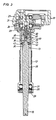
- the power tool illustrated in the drawing figures is a so called straight grinder which includes a central housing 10 with a rotation motor (not shown) and provided with a handle 11 at its rear end and a tubular extension 12 for rotationally supporting an output shaft 13 at its forward end.
- the housing extension 12 carries a grinding wheel safe guard 14.
- the outer end of the output shaft 13 is provided with a threaded portion 15 for carrying a grinding wheel mounting means 16. See Fig. 1.
- the described tool comprises a turbine type pneumatic motor to which motive pressure air is supplied via a conduit connection 17 and a throttle valve 18 in the handle 11.
- the throttle valve 18 is controlled by a lever 19.
- the output shaft 13 is provided with a gear wheel 21 which is a part of a reduction gearing disposed in the housing 10 and which connects the motor to the output shaft 13.
- the purpose of this gearing is to reduce the very high operation speed of the turbine motor to a speed suitable for grinding wheel operation. Since the motor and the reduction gearing are not parts of the invention they are not described in further detail.
- the output shaft 13 comprises a first section 23 which carries the gear wheel 21 and which is journalled in the housing 10 in two bearings 24,25.
- the output shaft 13 further comprises a second section 26 which is journalled in a single ball bearing 27 mounted in a socket portion 28 at the outer end of the tubular housing extension 12.
- the tubular housing extension 12 is terminated by a ring element 29 which is threaded into the outer end of the socket portion 28 to form an axial support for the bearing 27.
- the second output shaft section 26 is joined with the first shaft section 23 by means of a connection device 30.
- the connection device 30 comprises a sleeve element 31 which at its rear end is formed with a conical socket portion 32 for interengagement with a conical surface 33 on the first shaft section 23 for securing the sleeve element 31 to the latter.
- the sleeve element 31 is formed with a central recess 34 of rectangular cross section for cooperation with a central projection 35 of a matching rectangular shape protruding from a cylindrical rear end portion 36 of the second shaft section 26, thereby forming a torque transferring coupling device between the two shaft sections 23,26. See Fig. 5.
- the sleeve element 31 has a coaxial bore 38 extending between the recess 34 and the conical socket portion 32, and a mounting screw 39 extends through the bore 38 and engages an insertion member 40 which is threaded into a coaxial bore 41 in the first shaft section 23.
- the mounting screw 39 applies an axial pretension force on the sleeve element 31 to rigidly secure the latter to the first shaft section 23.
- the sleeve element 31 At its forward end, the sleeve element 31 comprises a cylindrical socket portion 42 in which is mounted the outer race of a single-row ball bearing 43.
- the inner race of the bearing 43 is mounted on the cylindrical end portion 36 of the second shaft section 26, whereby the bearing 43 forms a radial support and guide means with a very small radial play between the two shaft sections 23,26.
- An important characteristic of the ball bearing guide is the ability to allow a certain flexibility to angle deviations between the two shaft sections 23,26 without any radial play. This is an important characteristic of the shaft connection, because the second shaft section 26 is journalled in one bearing only and has to be accurately supported radially not to cause vibrations due to an untrue rotation at its inner end. Since both of the ball bearings 43 and 27 are of the single-row type, there is allowed a certain angle deviation between the shaft sections 23,26, and there will be no built-in bending stresses in the bearings 43,27 , the shaft sections 23,26 and the connection device 30.
- the described power tool is of the type having a high speed motor and a reduction gearing, but the invention is as well applicable on a tool having a low speed motor and lacking a reduction gearing.
- the motor shaft forms the first output shaft section, i.e. the connection sleeve element 31 is mounted directly on the motor shaft.
Landscapes
- Engineering & Computer Science (AREA)
- Mechanical Engineering (AREA)
- Connection Of Motors, Electrical Generators, Mechanical Devices, And The Like (AREA)
- Flexible Shafts (AREA)
- Constituent Portions Of Griding Lathes, Driving, Sensing And Control (AREA)
Claims (4)
- Drehmotorwerkzeug mit einem Gehäuse (10) mit einem röhrenförmigen Fortsatz (12), einem Rotationsmotor und einer Abtriebswelle (13), die mit dem Motor verbunden ist und einen ersten Abschnitt (23), der in dem Gehäuse (10) mit Hilfe von zwei axial beabstandeten Lagern (24, 25) gelagert ist, einen zweiten Abschnitt (26), der mit Hilfe eines einzigen Lagers (27) in dem röhrenförmigen Fortsatz (12) gelagert ist, und eine Verbindungseinrichtung (30) aufweist, die den ersten Wellenabschnitt (23) mit dem zweiten Wellenabschnitt (26) treibend verbindet, dadurch gekennzeichnet, daß die Verbindungseinrichtung (30) ein Hülsenelement (31), das auf einer Seite starr an entweder dem ersten Wellenabschnitt (23) oder dem zweiten Wellenabschnitt (26) befestigt ist und an dessen anderer Seite ein Endbereich (36) des jeweils anderen zweiten Wellenabschnittes (26) bzw. ersten Wellenabschnittes (23) aufnehmbar ist, Kupplungsmittel (34, 35) zur Übertragung von Drehmoment zwischen dem Hülsenelement (31) und dem Endbereich (36) sowie ein Kugellager (43) aufweist, das zwischen dem Hülsenelement (31) und dem Endbereich (36) angeordnet ist und Stützmittel für die genaue radiale Führung des Endbereichs (36) relativ zu dem Hülsenelement (31) bildet.
- Motorwerkzeug nach Anspruch 1, dadurch gekennzeichnet, daß die Kupplungsmittel (34, 35) einen mittigen Vorsprung (35) mit im wesentlichen rechteckigem Querschnitt, der sich axial vom Endbereich (36) erstreckt, und eine mittige Ausnehmung (34) von im wesentlichen rechteckigem Querschnitt in dem Hülsenelement (31) aufweisen, die zu dem Vorsprung (35) paßt.
- Motorwerkzeug nach Anspruch 1 oder 2, dadurch gekennzeichnet, daß das Hülsenelement (31) starr an dem ersten Wellenabschnitt (23) durch gegenseitiges Angreifen einer konischen Buchse (32) in dem Hülsenelement (31) an einer konischen Fläche (33) an dem ersten Wellenabschnitt (23) befestigt ist und der Endbereich (36) an dem zweiten Wellenabschnitt (26) ausgebildet ist.
- Motorwerkzeug nach einem der Ansprüche 1 bis 3, dadurch gekennzeichnet, daß der erste Wellenabschnitt (23) mit dem Rotor des Drehmotors über ein Untersetzungsgetriebe verbunden ist.
Applications Claiming Priority (3)
| Application Number | Priority Date | Filing Date | Title |
|---|---|---|---|
| SE9700842 | 1997-03-10 | ||
| SE9700842A SE511335C2 (sv) | 1997-03-10 | 1997-03-10 | Roterande motorverktyg med förlängd utgående axel |
| PCT/SE1998/000439 WO1998040190A1 (en) | 1997-03-10 | 1998-03-10 | Rotary power tool with an extended output shaft |
Publications (2)
| Publication Number | Publication Date |
|---|---|
| EP1007277A1 EP1007277A1 (de) | 2000-06-14 |
| EP1007277B1 true EP1007277B1 (de) | 2002-10-09 |
Family
ID=20406083
Family Applications (1)
| Application Number | Title | Priority Date | Filing Date |
|---|---|---|---|
| EP98909930A Expired - Lifetime EP1007277B1 (de) | 1997-03-10 | 1998-03-10 | Kraftangetriebenes werkzeug mit verlängerter antriebswelle |
Country Status (6)
| Country | Link |
|---|---|
| US (1) | US6186879B1 (de) |
| EP (1) | EP1007277B1 (de) |
| JP (1) | JP2001514581A (de) |
| DE (1) | DE69808648T2 (de) |
| SE (1) | SE511335C2 (de) |
| WO (1) | WO1998040190A1 (de) |
Families Citing this family (10)
| Publication number | Priority date | Publication date | Assignee | Title |
|---|---|---|---|---|
| ES2235423T3 (es) * | 1998-12-31 | 2005-07-01 | C. & E. FEIN GMBH | Herramienta electrica, especialmente amoladora angular. |
| USD456231S1 (en) | 2001-06-27 | 2002-04-30 | Ting-Yuan Chen | Pneumatic tool |
| DE102004027032B4 (de) * | 2004-06-02 | 2007-04-12 | MV Marketing und Vertriebs-GmbH & Co. KG Wieländer + Schill | Materialabtragendes Werkzeug sowie Verfahren zum Auftrennen von Schweißnähten |
| US7997169B1 (en) * | 2006-04-13 | 2011-08-16 | Hack Timothy L | Housed extension bar |
| USD559057S1 (en) * | 2006-08-22 | 2008-01-08 | Jim-Lieh Pan | Body for an air cut-off tool |
| JP5297392B2 (ja) * | 2009-07-06 | 2013-09-25 | 株式会社マキタ | サンダー |
| EP3548224B1 (de) * | 2016-12-05 | 2021-05-26 | Atlas Copco Industrial Technique AB | Drehmomentimpulsschrauber |
| CN107214583A (zh) * | 2017-06-29 | 2017-09-29 | 任青礼 | 一种皮鞋用吸尘打磨装置 |
| DE102018216910A1 (de) * | 2018-10-02 | 2020-04-02 | Zf Friedrichshafen Ag | Übersetzungsgetriebe für ein Fahrzeug mit einer Elektromaschine |
| USD925315S1 (en) * | 2019-08-15 | 2021-07-20 | Vis, Llc | Cut off tool |
Family Cites Families (13)
| Publication number | Priority date | Publication date | Assignee | Title |
|---|---|---|---|---|
| GB591661A (en) | 1945-05-16 | 1947-08-25 | Central Tool & Equipment Compa | Improvements in and relating to portable high speed electric grinding, polishing anddrilling machines |
| US1697046A (en) * | 1923-12-03 | 1929-01-01 | Gen Motors Corp | Tool-spindle mounting |
| FR37018E (fr) | 1929-06-07 | 1930-09-22 | Machine à rectifier à main | |
| US2099280A (en) * | 1933-10-21 | 1937-11-16 | William H Keller Inc | Portable pressure fluid actuated tool |
| US2112695A (en) * | 1934-07-23 | 1938-03-29 | Independent Pneumatic Tool Co | Portable electric tool |
| US2097944A (en) * | 1937-02-01 | 1937-11-02 | Cincinnati Electrical Tool Com | Grinding machine |
| US2342610A (en) * | 1940-11-01 | 1944-02-22 | Elliott Mfg Co | Handpiece |
| CH236816A (de) * | 1943-10-29 | 1945-03-15 | Burkhalter Emil | Schleifmaschine. |
| US2451658A (en) * | 1943-12-03 | 1948-10-19 | Bugtember Ettore | Mounting of grinding wheels, especially on grinding machines |
| US2582873A (en) * | 1947-04-28 | 1952-01-15 | Independent Pneumatic Tool Co | Flexible spindle for rotary power tools |
| GB658278A (en) | 1948-05-31 | 1951-10-03 | George William Sanders | Improvements in or relating to devices for connecting tool heads to flexible shafts |
| US3410030A (en) | 1966-01-11 | 1968-11-12 | Chicago Pneumatic Tool Co | Safety overspeed control mechanism for rotary tools |
| SE321422B (de) | 1968-02-20 | 1970-03-02 | Bahco Ab |
-
1997
- 1997-03-10 SE SE9700842A patent/SE511335C2/sv not_active IP Right Cessation
-
1998
- 1998-03-10 JP JP53951898A patent/JP2001514581A/ja active Pending
- 1998-03-10 WO PCT/SE1998/000439 patent/WO1998040190A1/en not_active Ceased
- 1998-03-10 EP EP98909930A patent/EP1007277B1/de not_active Expired - Lifetime
- 1998-03-10 DE DE69808648T patent/DE69808648T2/de not_active Expired - Fee Related
- 1998-03-10 US US09/380,880 patent/US6186879B1/en not_active Expired - Lifetime
Also Published As
| Publication number | Publication date |
|---|---|
| SE9700842L (sv) | 1998-09-11 |
| SE511335C2 (sv) | 1999-09-13 |
| DE69808648D1 (de) | 2002-11-14 |
| US6186879B1 (en) | 2001-02-13 |
| DE69808648T2 (de) | 2003-08-07 |
| JP2001514581A (ja) | 2001-09-11 |
| EP1007277A1 (de) | 2000-06-14 |
| WO1998040190A1 (en) | 1998-09-17 |
| SE9700842D0 (sv) | 1997-03-10 |
Similar Documents
| Publication | Publication Date | Title |
|---|---|---|
| EP1007277B1 (de) | Kraftangetriebenes werkzeug mit verlängerter antriebswelle | |
| JP4982181B2 (ja) | アングルドライブ装置及びピニオン調整を備えた動力工具 | |
| CA1261641A (en) | Quick disconnect mechanism for selectively securing a shaft to a power take-off end yoke | |
| US8187107B2 (en) | Push button quick disconnect yoke | |
| US20110168419A1 (en) | Modified power tool | |
| CN103648724A (zh) | 干墙起子机 | |
| GB2242487A (en) | A two-speed torque responsive planetary power transmission for a power tool | |
| EP1813508B1 (de) | Lenkvorrichtung | |
| CN111343850A (zh) | 车辆端动力输出轴连接装置、辅助设备端动力输出轴连接装置以及包括车辆端和辅助设备端动力输出轴连接装置的动力输出轴连接单元 | |
| EP1605178A2 (de) | Flanscheinheit für die Fassung der Wälzlager und die Abstüztung eines Endanschluss einer Antriebswelle | |
| US20090126960A1 (en) | Portable Power Tool with Drive Shaft Lock Means | |
| US20030056625A1 (en) | Output shaft and concentrically mounted attachments therefor | |
| JP7735440B2 (ja) | 工具取付ユニット | |
| KR920001659B1 (ko) | 죠인트 장치 | |
| JP2007507361A (ja) | 遊星型減速歯車装置を備えた動力工具 | |
| JPH01279120A (ja) | 軸継手 | |
| US5251365A (en) | Method for making ball screw nut | |
| US5868626A (en) | Universal joint yoke having axially-extending grooves | |
| JP2002254259A (ja) | 2軸同時締付工具 | |
| JPH11156603A (ja) | スピンドルユニット | |
| JP3991578B2 (ja) | 特殊デフ装置の組立方法および同方法に用いられる治具 | |
| US20060169082A1 (en) | Shaft assembly | |
| KR200382866Y1 (ko) | 로타리버용 다이 그라인더 | |
| JP3457194B2 (ja) | 電動式動力舵取装置 | |
| JP2883763B2 (ja) | ディファレンシャルリングギヤ一体研削装置 |
Legal Events
| Date | Code | Title | Description |
|---|---|---|---|
| PUAI | Public reference made under article 153(3) epc to a published international application that has entered the european phase |
Free format text: ORIGINAL CODE: 0009012 |
|
| 17P | Request for examination filed |
Effective date: 19991005 |
|
| AK | Designated contracting states |
Kind code of ref document: A1 Designated state(s): DE FR GB IT |
|
| GRAG | Despatch of communication of intention to grant |
Free format text: ORIGINAL CODE: EPIDOS AGRA |
|
| 17Q | First examination report despatched |
Effective date: 20010917 |
|
| GRAG | Despatch of communication of intention to grant |
Free format text: ORIGINAL CODE: EPIDOS AGRA |
|
| GRAH | Despatch of communication of intention to grant a patent |
Free format text: ORIGINAL CODE: EPIDOS IGRA |
|
| GRAH | Despatch of communication of intention to grant a patent |
Free format text: ORIGINAL CODE: EPIDOS IGRA |
|
| GRAA | (expected) grant |
Free format text: ORIGINAL CODE: 0009210 |
|
| AK | Designated contracting states |
Kind code of ref document: B1 Designated state(s): DE FR GB IT |
|
| REG | Reference to a national code |
Ref country code: GB Ref legal event code: FG4D |
|
| REF | Corresponds to: |
Ref document number: 69808648 Country of ref document: DE Date of ref document: 20021114 |
|
| ET | Fr: translation filed | ||
| PLBE | No opposition filed within time limit |
Free format text: ORIGINAL CODE: 0009261 |
|
| STAA | Information on the status of an ep patent application or granted ep patent |
Free format text: STATUS: NO OPPOSITION FILED WITHIN TIME LIMIT |
|
| 26N | No opposition filed |
Effective date: 20030710 |
|
| PGFP | Annual fee paid to national office [announced via postgrant information from national office to epo] |
Ref country code: GB Payment date: 20070307 Year of fee payment: 10 |
|
| PGFP | Annual fee paid to national office [announced via postgrant information from national office to epo] |
Ref country code: DE Payment date: 20070308 Year of fee payment: 10 |
|
| PGFP | Annual fee paid to national office [announced via postgrant information from national office to epo] |
Ref country code: IT Payment date: 20070523 Year of fee payment: 10 |
|
| PGFP | Annual fee paid to national office [announced via postgrant information from national office to epo] |
Ref country code: FR Payment date: 20070308 Year of fee payment: 10 |
|
| GBPC | Gb: european patent ceased through non-payment of renewal fee |
Effective date: 20080310 |
|
| REG | Reference to a national code |
Ref country code: FR Ref legal event code: ST Effective date: 20081125 |
|
| PG25 | Lapsed in a contracting state [announced via postgrant information from national office to epo] |
Ref country code: DE Free format text: LAPSE BECAUSE OF NON-PAYMENT OF DUE FEES Effective date: 20081001 |
|
| PG25 | Lapsed in a contracting state [announced via postgrant information from national office to epo] |
Ref country code: FR Free format text: LAPSE BECAUSE OF NON-PAYMENT OF DUE FEES Effective date: 20080331 |
|
| PG25 | Lapsed in a contracting state [announced via postgrant information from national office to epo] |
Ref country code: GB Free format text: LAPSE BECAUSE OF NON-PAYMENT OF DUE FEES Effective date: 20080310 |
|
| PG25 | Lapsed in a contracting state [announced via postgrant information from national office to epo] |
Ref country code: IT Free format text: LAPSE BECAUSE OF NON-PAYMENT OF DUE FEES Effective date: 20080310 |