EP1006756B2 - Sensor controlled hot plate with sensor arranged below the plate - Google Patents
Sensor controlled hot plate with sensor arranged below the plate Download PDFInfo
- Publication number
- EP1006756B2 EP1006756B2 EP99123600A EP99123600A EP1006756B2 EP 1006756 B2 EP1006756 B2 EP 1006756B2 EP 99123600 A EP99123600 A EP 99123600A EP 99123600 A EP99123600 A EP 99123600A EP 1006756 B2 EP1006756 B2 EP 1006756B2
- Authority
- EP
- European Patent Office
- Prior art keywords
- cooking field
- sensor
- heat radiation
- field plate
- plate
- Prior art date
- Legal status (The legal status is an assumption and is not a legal conclusion. Google has not performed a legal analysis and makes no representation as to the accuracy of the status listed.)
- Expired - Lifetime
Links
Images

Classifications
-
- H—ELECTRICITY
- H05—ELECTRIC TECHNIQUES NOT OTHERWISE PROVIDED FOR
- H05B—ELECTRIC HEATING; ELECTRIC LIGHT SOURCES NOT OTHERWISE PROVIDED FOR; CIRCUIT ARRANGEMENTS FOR ELECTRIC LIGHT SOURCES, IN GENERAL
- H05B3/00—Ohmic-resistance heating
- H05B3/68—Heating arrangements specially adapted for cooking plates or analogous hot-plates
- H05B3/74—Non-metallic plates, e.g. vitroceramic, ceramic or glassceramic hobs, also including power or control circuits
- H05B3/746—Protection, e.g. overheat cutoff, hot plate indicator
-
- F—MECHANICAL ENGINEERING; LIGHTING; HEATING; WEAPONS; BLASTING
- F24—HEATING; RANGES; VENTILATING
- F24C—DOMESTIC STOVES OR RANGES ; DETAILS OF DOMESTIC STOVES OR RANGES, OF GENERAL APPLICATION
- F24C15/00—Details
- F24C15/10—Tops, e.g. hot plates; Rings
- F24C15/102—Tops, e.g. hot plates; Rings electrically heated
- F24C15/105—Constructive details concerning the regulation of the temperature
-
- F—MECHANICAL ENGINEERING; LIGHTING; HEATING; WEAPONS; BLASTING
- F24—HEATING; RANGES; VENTILATING
- F24C—DOMESTIC STOVES OR RANGES ; DETAILS OF DOMESTIC STOVES OR RANGES, OF GENERAL APPLICATION
- F24C7/00—Stoves or ranges heated by electric energy
- F24C7/08—Arrangement or mounting of control or safety devices
- F24C7/082—Arrangement or mounting of control or safety devices on ranges, e.g. control panels, illumination
- F24C7/083—Arrangement or mounting of control or safety devices on ranges, e.g. control panels, illumination on tops, hot plates
-
- H—ELECTRICITY
- H05—ELECTRIC TECHNIQUES NOT OTHERWISE PROVIDED FOR
- H05B—ELECTRIC HEATING; ELECTRIC LIGHT SOURCES NOT OTHERWISE PROVIDED FOR; CIRCUIT ARRANGEMENTS FOR ELECTRIC LIGHT SOURCES, IN GENERAL
- H05B2213/00—Aspects relating both to resistive heating and to induction heating, covered by H05B3/00 and H05B6/00
- H05B2213/07—Heating plates with temperature control means
Definitions
- the present invention relates to a sensor-controlled cooktop with a cooktop panel, in particular of glass ceramic or glass, with at least one cooking zone which is heated by means of a arranged below the cooktop heating element, as well as arranged below the cooktop plate and against the underside in the area of a limited area Meßfleckes directed heat radiation sensor unit, which is in communication with a control unit for controlling the heating power of the heating element.
- Such a hob is known from the document GB 2 072 334 A , wherein below the hob plate a parabolic reflector arrangement is provided.
- the reflector assembly collects the radiated from the bottom of the bottom of a parked on the cooktop panel and heated by the heating element pan heat radiation and directs these via a connected optical connection line to an infrared-sensitive photodiode. The heat radiation thus detected is used as a signal for controlling the heating power of the heating element.
- Object of the present invention is to ensure sufficiently accurate pot-independent in a sensor-controlled hob according to the preamble of claim 1, the heat output control.
- the value of the transmittance of the cooktop panel at least in the region of the measuring spot at least in the spectral measuring range of the heat radiation sensor unit is less than 30%, preferably less than 10% and in particular approximately 0%. Due to the low selected value of the transmittance of the material of the cooktop panel ensures that the disturbing, because unknown influence of radiated from the bottom of the pot in the direction of the cooktop plate and thus on the heat radiation sensor heat radiation is low. This is particularly important because the value of the emissivity of the bottom of the pot bottom can typically range between 20 and 90%, depending on the cooking pot type. According to the invention, it is thus ensured that the thermal radiation sensor receives substantially exclusively the heat radiation radiated from the underside of the hob plate.
- the emissivity of the lower side of the cooktop panel is at least 60%, in particular more than 90%, at least in the region of the measuring spot at least in the spectral measuring range of the heat radiation sensor unit.
- the measuring accuracy according to the invention is at least sufficient to be able to carry out frying or frying operations with satisfactory cooking results.
- pots or pans with flat as possible and thus over a large area resting on the top of the hob plate soil.
- a measuring spot with suitable transmission and emission properties can be realized if the hob plate is provided on its underside in the region of the measuring spot with a dark, in particular black, emission layer.
- the transmission or emission values are then essentially independent of manufacturing variations and on the other over the life of the hob plate despite their aging substantially constant. Furthermore, the values are then independent of the properties of the material of the cooktop panel or manufacturer or tint independent.
- a suitable size of the measuring spot moves at about 1 to 4 cm 2 . This ensures that the measuring spot on the one hand is not too large, which would affect a uniform cooking result in the pan or the pot. On the other hand, the measuring spot must not be too small, so that the influence of the heat radiation of the pot bottom on the glass ceramic remains large enough. In the case of too small surface area of the measuring spot whose sensed temperature is despite the low thermal conductivity of, for example, glass or glass ceramic essentially exclusively dependent on the temperature of the glass ceramic in the vicinity of the measuring spot.
- the aim of the hob according to the invention is to close or to regulate the temperature of the parked on the hob and heated cooking vessel.
- the thermal radiation sensor unit has a special filter whose spectral transmission range is substantially between about 4 and 8 microns. In this range, both the value of the transmittance and the average degree of reflection of the material of the hob plate in typical glass ceramic cooktop panels is sufficiently low. This results in this wavelength range, a high emissivity of the underside of the hob plate and associated high sensitivity and accuracy.
- the spectral transmission range may typically be between about 10 to 20 microns. Also in this range, the value of the transmittance in typical glass ceramic material is about 0% and that of the reflectance is significantly lower than in the two adjacent adjacent wavelength ranges. The choice of a suitable spectral filter depends, in particular, on its price and on the sensitivity or measuring and control accuracy of the sensor-controlled cooking field achievable in the respective wavelength range.
- a measuring shaft is arranged on the underside of the hob plate in the region of the measuring spot in which the heat radiation sensor unit is directed onto the measuring spot of the hob plate is. This measure ensures that the temperature influence of the measuring spot by the heat radiation radiating heating element is greatly reduced or excluded. It is particularly advantageous if the measuring shaft is as close as possible to the underside of the hob plate, and if the radiation channel in the measuring well as well as possible isolated from the space outside of the measuring shaft.
- the heating element moves the measuring well and thus the measuring spot substantially on all sides.
- an arithmetic unit of the cooktop calculates from the signal of the heat radiation sensor unit and stored in a memory unit characteristics of the hob, the temperature of the bottom of a parked on the cooktop plate heated cooking vessel and passes them to the control unit for controlling the heating power on. From findings obtained in laboratory experiments, typical characteristics for the relationship of the measuring signal of the sensor unit to the prevailing pot bottom temperature can be obtained. These are then stored in the storage unit and are appropriately linked during the cooking process with the measurement signal of the heat radiation sensor unit. In turn, control signals for the heating power of the corresponding heating element are determined from the soil temperature derived therefrom. The accuracy of the system can be increased in particular in large-scale cooking vessels such as casserole pans, if at least two heat radiation sensor units are used. Furthermore, it is expedient to realize a known pan detection unit or to use the measuring signals of the heat radiation sensor unit for pot detection.
- a cooktop 1 has a cooktop panel 3 made of glass ceramic material, on the upper side of which heatable zones are marked by means of decorative printing ( Fig. 1 ). These zones are assigned below the hob plate 3 respectively corresponding known per se metallic radiator pots 5. These are pressed by means of known per se, not shown aids to the underside of the hob plate 3.
- the radiator pot 5 has a radiator insulation 7 on the floor and on the circumference. In this or on this a known radiation heating 9 is supported, which emits heat radiation when feeding with electric current, in particular in the direction of the underside of the hob plate 3. Above the radiator pot 5 and the Strahlungssammlungleiters 9 a frying pan 11 is placed on top of the hob plate 3.
- the emissivity ⁇ of the underside of the pot bottom 11 is typically about 10 to 20% for stainless steel pots and typically about 80 to 90% for a black enameled pot bottom.
- a tubular measuring shaft 15 is provided, the upper end side rests close to the underside of the hob plate 3.
- the diameter of the measuring shaft is about 1 to 2 cm.
- the measuring shaft 15 is provided with suitable insulation means for thermal foreclosure of the measuring arrangement described below, in particular with respect to the heating element 9. Furthermore, the measuring shaft 15 on its inner peripheral side to increase the sensitivity of the measuring device described below, a reflection layer 17.
- the limited of the measuring shaft 15 circular area on the underside of the hob plate 3 serves as a measuring spot 18 of the measuring arrangement.
- a heat radiation sensitive infrared sensor 19 is arranged at the measuring spot 18 opposite end of the measuring shaft 15. This is preceded by an infrared optics 21 with a spectral filter whose spectral passband is between about 5 and 8 microns.
- an aperture 23 in the bottom of the measuring shaft 15 of the infrared sensor 19 is directed to the measuring spot 18 of the hob plate 3.
- a suitable sensor window 25 is set in the aperture 23.
- the infrared sensor 19 For cooling the infrared sensor 19, this sits in a cooling duct socket of the bottom of the radiator pot 5, the cooling air when necessary (cooling air arrows) is supplied. Furthermore, a cooling channel 27 is provided between the radiator pot 5 and the radiator insulation 7. This ensures that the permissible continuous operating temperature of the infrared sensor 19 of about 100 to 120 ° C is not exceeded ( Fig. 1 ).
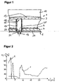
- the transmittance of the glass-ceramic cooktop panel in the spectral filter defined by the spectral range of the infrared sensor 19 of about 5 to 8 microns according to Fig. 2 a transmittance ⁇ of about 0%.
- the Meßund control accuracy of the system is higher, the better the thermal coupling of the pot bottom 11 to the glass ceramic plate 3 on the one hand and their coupling to the infrared transmitter 19 on the other hand is realized.
- the underside of the hob plate 3 with a black color layer 31 In order to be fundamentally independent of the material properties of the hob plate, according to the second embodiment according to Fig. 5 covered in the region of the measuring spot 18, the underside of the hob plate 3 with a black color layer 31.
- the value of the transmittance ⁇ is ideally about 0% and that of the emissivity ⁇ is about 100% ( Fig. 5 ).
- the heating conductor 9 moves according to Fig. 3 the measuring shaft 15 substantially on all sides. Whether the measuring shaft 15 is arranged at the edge of the radiator pot 5 or rather in the central region, is dependent on the particular circumstances. For example, it may be advantageous in the use of two measuring wells 15 in a radiator pot 5 for reasons of accuracy, in spite of, for example, uneven temperature distribution in the bottom of the pan, when the two measuring wells 15 are each arranged in the edge region of the radiator pot 5 ( Fig. 3 ).
- the underside of the heated by the Strahlungssammlungleiter 9 pot bottom 11 continuously radiates heat radiation to the arranged underneath cooktop 3.
- the Strahlungssammlungleiter 9 and the cooktop panel 3 heat radiation to the pot bottom 11. Plus finds in the areas where the pot bottom touches the hotplate heat conduction between the two takes place. The same also applies in the direction parallel to the hob plate 3 within this.
- the infrared sensor 19 is shielded by the measuring shaft 15 from the heat radiation of the Strahlungssammlungleiters 9. In addition, it is largely shielded by the properties of the material of the hob plate of the heat radiation of the cooking vessel 11.
- a relationship between the radiated from the bottom of the glass ceramic hob plate 3 in the region of the measuring spot 18 to the infrared sensor 19 heat radiation and the temperature of the bottom of the frying pan 11 can now be determined.
- a computing unit 41 of the hob determines a corresponding output signal from the measured value S of the infrared sensor 19 and stored in a memory unit 43 of the hob 1 characteristics of the arrangement from which a control unit 45 of the hob 1, a heating power signal P for the Strahlungssammlungleiter. 9 derives ( Fig. 4 ). This makes it possible; that, for example, a frying temperature of 180 ° C predetermined by an operator via input elements known per se is automatically adjusted by the control unit 45.
Description
Die vorliegende Erfindung betrifft ein sensorgesteuertes Kochfeld mit einer Kochfeldplatte, insbesondere aus Glaskeramik oder Glas, mit zumindest einer Kochzone, die mittels eines unterhalb der Kochfeldplatte angeordneten Heizelementes beheizbar ist, sowie mit einer unterhalb der Kochfeldplatte angeordneten und gegen deren Unterseite im Bereich eines flächenmäßig begrenzten Meßfleckes gerichteten Wärmestrahlungs-Sensoreinheit, die in Verbindung steht mit einer Steuereinheit zur Regelung der Heizleistung des Heizelementes.The present invention relates to a sensor-controlled cooktop with a cooktop panel, in particular of glass ceramic or glass, with at least one cooking zone which is heated by means of a arranged below the cooktop heating element, as well as arranged below the cooktop plate and against the underside in the area of a limited area Meßfleckes directed heat radiation sensor unit, which is in communication with a control unit for controlling the heating power of the heating element.
Ein derartiges Kochfeld ist bekannt aus der Druckschrift
Aufgabe der vorliegenden Erfindung ist es, bei einem sensorgesteuerten Kochfeld nach dem Oberbegriff des Patentanspruches 1 die Heizleistungsregelung topfunabhängig ausreichend genau zu gewährleisten.Object of the present invention is to ensure sufficiently accurate pot-independent in a sensor-controlled hob according to the preamble of
Erfindungsgemäß ist dies dadurch erreicht, daß der Wert des Transmissionsgrades der Kochfeldplatte zumindest im Bereich des Meßfleckes zumindest im spektralen Meßbereich der Wärmestrahlungs-Sensoreinheit weniger als 30 %, vorzugsweise weniger als 10 % und insbesondere annähernd etwa 0 % beträgt. Durch den gering gewählten Wert des Transmissionsgrades des Materials der Kochfeldplatte ist sichergestellt, daß der störende, weil unbekannte Einfluß der vom Topfboden in Richtung auf die Kochfeldplatte und damit auf den Wärmestrahlungs-Sensor abgestrahlten Wärmestrahlung gering ist. Dies ist insbesondere deshalb wichtig, weil sich der Wert des Emissionsgrades der Topfbodenunterseite abhängig vom Kochtopftyp typischerweise zwischen 20 und 90 % bewegen kann. Erfindungsgemäß ist also sichergestellt, daß der Wärmestrahlungs-Sensor im wesentlichen bis ausschließlich die von der Unterseite der Kochfeldplatte abgestrahlte Wärmestrahlung empfängt.According to the invention this is achieved in that the value of the transmittance of the cooktop panel at least in the region of the measuring spot at least in the spectral measuring range of the heat radiation sensor unit is less than 30%, preferably less than 10% and in particular approximately 0%. Due to the low selected value of the transmittance of the material of the cooktop panel ensures that the disturbing, because unknown influence of radiated from the bottom of the pot in the direction of the cooktop plate and thus on the heat radiation sensor heat radiation is low. This is particularly important because the value of the emissivity of the bottom of the pot bottom can typically range between 20 and 90%, depending on the cooking pot type. According to the invention, it is thus ensured that the thermal radiation sensor receives substantially exclusively the heat radiation radiated from the underside of the hob plate.
Um eine ausreichende Meßempfindlichkeit des sensorgesteuerten Kochfeldes erreichen zu können, beträgt erfindungsgemäß der Emissionsgrad der Unterseite der Kochfeldplatte zumindest im Bereich des Meßfleckes zumindest im spektralen Meßbereich der Wärmestrahlungs-Sensoreinheit zumindest 60 %, insbesondere mehr als 90 %. Die erfindungsgemäße Meßgenauigkeit ist zumindest ausreichend, um Brat- oder Fritiervorgänge bei zufriedenstellenden Garergebnissen durchführen zu können. Zur Steigerung der Genauigkeit des sensorgesteuerten Systems ist es zweckmäßig, Töpfe beziehungsweise Pfannen mit möglichst ebenem und damit großflächig auf der Oberseite der Kochfeldplatte aufliegendem Boden zu verwenden.In order to be able to achieve a sufficient measuring sensitivity of the sensor-controlled cooktop, the emissivity of the lower side of the cooktop panel is at least 60%, in particular more than 90%, at least in the region of the measuring spot at least in the spectral measuring range of the heat radiation sensor unit. The measuring accuracy according to the invention is at least sufficient to be able to carry out frying or frying operations with satisfactory cooking results. To increase the accuracy of the sensor-controlled system, it is expedient to use pots or pans with flat as possible and thus over a large area resting on the top of the hob plate soil.
Mit geringem Aufwand ist ein Meßfleck mit geeigneten Transmissions- und Emissionseigenschaften realisierbar, wenn die Kochfeldplatte an ihrer Unterseite im Bereich des Meßfleckes mit einer dunklen insbesondere schwarzen Emissionsschicht versehen ist. Die Transmissions- bzw. Emissionswerte sind dann zum einen unabhängig von Fertigungsstreuungen und zum anderen über die Lebensdauer der Kochfeldplatte trotz deren Alterung im wesentlichen konstant. Weiterhin sind die Werte dann auch unabhängig von den Eigenschaften des Materials der Kochfeldplatte bzw. hersteller- oder farbtönungsunabhägig.With little effort, a measuring spot with suitable transmission and emission properties can be realized if the hob plate is provided on its underside in the region of the measuring spot with a dark, in particular black, emission layer. The transmission or emission values are then essentially independent of manufacturing variations and on the other over the life of the hob plate despite their aging substantially constant. Furthermore, the values are then independent of the properties of the material of the cooktop panel or manufacturer or tint independent.
Eine geeignete Größe des Meßfleckes bewegt sich bei etwa 1 bis 4 cm2. Dadurch ist sichergestellt, daß der Meßfleck einerseits nicht zu groß ist, was ein gleichmäßiges Garergebnis in der Pfanne beziehungsweise dem Topf beeinträchtigen würde. Andererseits darf der Meßfleck auch nicht zu klein sein, damit der Einfluß der Wärmestrahlung des Topfbodens auf die Glaskeramik groß genug bleibt. Im Falle einer zu kleinen Flächenausdehnung des Meßflecks ist dessen abgefühlte Temperatur trotz der geringen Wärmeleitfähigkeit von beispielsweise Glas oder Glaskeramik im wesentlichen ausschließlich abhängig von der Temperatur der Glaskeramik in der Umgebung des Meßfleckes. Ziel des erfindungsgemäßen Kochfeldes ist es jedoch, auf die Temperatur des auf der Kochfeldplatte abgestellten und beheizten Gargefäßes zu schließen beziehungsweise diese zu regeln.A suitable size of the measuring spot moves at about 1 to 4 cm 2 . This ensures that the measuring spot on the one hand is not too large, which would affect a uniform cooking result in the pan or the pot. On the other hand, the measuring spot must not be too small, so that the influence of the heat radiation of the pot bottom on the glass ceramic remains large enough. In the case of too small surface area of the measuring spot whose sensed temperature is despite the low thermal conductivity of, for example, glass or glass ceramic essentially exclusively dependent on the temperature of the glass ceramic in the vicinity of the measuring spot. The aim of the hob according to the invention, however, is to close or to regulate the temperature of the parked on the hob and heated cooking vessel.
Gemäß einer bevorzugten Ausführungsform weist die Wärmestrahlungs-Sensoreinheit einen Spezialfilter auf, dessen spektraler Durchlaßbereich im wesentlichen zwischen etwa 4 und 8 µm liegt. In diesem Bereich ist sowohl der Wert des Transmissionsgrades als auch der des durchschnittlichen Reflexionsgrades des Materials der Kochfeldplatte bei typischen Glaskeramik-Kochfeldplatten ausreichend gering. Daraus ergibt sich in diesem Wellenlängenbereich ein hoher Emissionsgrad der Unterseite der Kochfeldplatte und damit verbunden eine hohe Meßempfindlichkeit und -genauigkeit. Alternativ kann der spektrale Durchlaßbereich typischerweise auch zwischen etwa 10 bis 20 µm liegen. Auch in diesem Bereich beträgt der Wert des Transmissionsgrades bei typischem Glaskeramikmaterial etwa 0 % und der des Reflexionsgrades ist deutlich geringer als in den beidseitig benachbarten Wellenlängenbereichen. Die Wahl eines geeigneten Spektralfilters ist insbesondere von dessen Preis abhängig sowie von der in dem jeweiligen Wellenlängenbereich erzielbaren Empfindlichkeit beziehungsweise Meß- und Regelgenauigkeit des sensorgesteuerten Kochfeldes.According to a preferred embodiment, the thermal radiation sensor unit has a special filter whose spectral transmission range is substantially between about 4 and 8 microns. In this range, both the value of the transmittance and the average degree of reflection of the material of the hob plate in typical glass ceramic cooktop panels is sufficiently low. This results in this wavelength range, a high emissivity of the underside of the hob plate and associated high sensitivity and accuracy. Alternatively, the spectral transmission range may typically be between about 10 to 20 microns. Also in this range, the value of the transmittance in typical glass ceramic material is about 0% and that of the reflectance is significantly lower than in the two adjacent adjacent wavelength ranges. The choice of a suitable spectral filter depends, in particular, on its price and on the sensitivity or measuring and control accuracy of the sensor-controlled cooking field achievable in the respective wavelength range.
Erfindungsgemäß ist an der Unterseite der Kochfeldplatte im Bereich des Meßfleckes ein Meßschacht angeordnet, in dem die Wärmestrahlungs-Sensoreinheit auf den Meßfleck der Kochfeldplatte gerichtet ist. Diese Maßnahme stellt sicher, daß die temperaturmäßige Beeinflussung des Meßfleckes durch das Wärmestrahlung abstrahlende Heizelement stark verringert beziehungsweise ausgeschlossen ist. Dabei ist es besonders günstig, wenn der Meßschacht möglichst dicht an der Unterseite der Kochfeldplatte anliegt, sowie wenn der Strahlungskanal im Meßschacht möglichst gut von dem Raum außerhalb des Meßschachtes isoliert ist.According to the invention, a measuring shaft is arranged on the underside of the hob plate in the region of the measuring spot in which the heat radiation sensor unit is directed onto the measuring spot of the hob plate is. This measure ensures that the temperature influence of the measuring spot by the heat radiation radiating heating element is greatly reduced or excluded. It is particularly advantageous if the measuring shaft is as close as possible to the underside of the hob plate, and if the radiation channel in the measuring well as well as possible isolated from the space outside of the measuring shaft.
Um eine möglichst gleichmäßige Wärmeverteilung im Topfboden und in der Kochfeldplatte und damit verbunden eine hohe Meßgenauigkeit zu erreichen, umzieht vorteilhafterweise das Heizelement den Meßschacht und damit den Meßfleck im wesentlichen allseitig.In order to achieve the most uniform possible heat distribution in the bottom of the pot and in the cooktop plate and, associated therewith, a high measuring accuracy, advantageously the heating element moves the measuring well and thus the measuring spot substantially on all sides.
Gemäß einer bevorzugten Ausführungsform berechnet eine Recheneinheit des Kochfeldes aus dem Signal der Wärmestrahlungs-Sensoreinheit und in einer Speichereinheit abgelegten Kenndaten des Kochfeldes die Temperatur des Bodens eines auf der Kochfeldplatte abgestellten beheizten Gargefäßes und gibt diese an die Steuereinheit zur Regelung der Heizleistung weiter. Aus in Laborversuchen gewonnenen Erkenntnissen können typische Kennzahlen für die Beziehung des Meßsignals der Sensoreinheit zur vorherrschenden Topfbodentemperatur gewonnen werden. Diese sind dann in der Speichereinheit abgelegt und werden beim Garvorgang mit dem Meßsignal der Wärmestrahlungs-Sensoreinheit geeignet verknüpft. Aus der daraus abgeleiteten Bodentemperatur werden dann wiederum Stellsignale für die Heizleistung des entsprechenden Heizelementes ermittelt. Die Genauigkeit des Systems kann insbesondere bei großflächigen Gargefäßen wie beispielsweise Bräterpfannen erhöht werden, wenn zumindest zwei Wärmestrahlungs-Sensoreinheiten verwendet werden. Weiterhin ist es zweckmäßig, eine an sich bekannte Topferkennungseinheit zu realisieren oder die Meßsignale der Wärmestrahlungs-Sensoreinheit zur Topferkennung zu verwenden.According to a preferred embodiment, an arithmetic unit of the cooktop calculates from the signal of the heat radiation sensor unit and stored in a memory unit characteristics of the hob, the temperature of the bottom of a parked on the cooktop plate heated cooking vessel and passes them to the control unit for controlling the heating power on. From findings obtained in laboratory experiments, typical characteristics for the relationship of the measuring signal of the sensor unit to the prevailing pot bottom temperature can be obtained. These are then stored in the storage unit and are appropriately linked during the cooking process with the measurement signal of the heat radiation sensor unit. In turn, control signals for the heating power of the corresponding heating element are determined from the soil temperature derived therefrom. The accuracy of the system can be increased in particular in large-scale cooking vessels such as casserole pans, if at least two heat radiation sensor units are used. Furthermore, it is expedient to realize a known pan detection unit or to use the measuring signals of the heat radiation sensor unit for pot detection.
Nachfolgend sind anhand schematischer Darstellungen zwei Ausführungsbeispiele des erfindungsgemäßen sensorgesteuerten Kochfeldes beschrieben.Two exemplary embodiments of the sensor-controlled cooktop according to the invention are described below with reference to schematic representations.
Es zeigen:
- Fig. 1
- in einer Schnittdarstellung abschnittsweise das Kochfeld mit darauf abgestelltem Topf gemäß dem ersten Ausführungsbeispiel,
- Fig. 2
- die Verläufe des Transmissions- und des Reflexionsgrades einer Glaskeramik-Kochfeldplatte im interessierenden Wellenlängenbereich,
- Fig. 3
- abschnittsweise in einer Ansicht von oben den Anordnung des Heizelementes im Bereich des Meßschachtes der Wärmestrahlungs-Sensoreinheit,
- Fig. 4
- ein Blockschaltbild wesentlicher Regelungseinheiten des sensorgesteuerten Kochfeldes und
- Fig. 5
- abschnittsweise den Bereich unterhalb der Kochfeldplatte im Bereich des Meßfleckes gemäß dem zweiten Ausführungsbeispiel in einer Schnittdarstellung gemäß
Figur 1
- Fig. 1
- in a sectional view, in sections, the hob with pot placed on it according to the first embodiment,
- Fig. 2
- the courses of the transmission and the reflectance of a glass ceramic hob plate in the wavelength range of interest,
- Fig. 3
- in sections in a view from above the arrangement of the heating element in the region of the measuring shaft of the heat radiation sensor unit,
- Fig. 4
- a block diagram of essential control units of the sensor-controlled hob and
- Fig. 5
- Sectionally the area below the hob plate in the region of the measuring spot according to the second embodiment in a sectional view according to
FIG. 1 ,
Ein Kochfeld 1 weist eine Kochfeldplatte 3 aus Glaskeramikmaterial auf, auf deren Oberseite mit Hilfe einer Dekorbedruckung beheizbare Zonen markiert sind (
Der Transmissionsgrad der Glaskeramik-Kochfeldplatte weist in dem durch den Spektralfilter definierten spektralen Meßbereich des Infrarotsensors 19 von etwa 5 bis 8 µm gemäß
Um grundsätzlich unabhängig von den Materialeigenschaften der Kochfeldplatte zu sein, ist gemäß dem zweiten Ausführungsbeispiel nach
Um eine möglichst gleichmäßige Wärmeverteilung im Topfboden 11 sowie in der Glaskeramikplatte 3 zu erreichen, umzieht der Heizleiter 9 gemäß
Beim Betrieb des sensorgesteuerten Kochfeldes 1 strahlt die Unterseite des von dem Strahlungsheizleiter 9 beheizten Topfbodens 11 fortwährend Wärmestrahlung auf die darunter angeordnete Kochfeldplatte 3. Andererseits strahlen sowohl der Strahlungsheizleiter 9 als auch die Kochfeldplatte 3 Wärmestrahlung zum Topfboden 11. Zuzüglich findet in den Bereichen, in denen der Topfboden die Kochfeldplatte berührt Wärmeleitung zwischen beiden statt. Dasselbe gilt auch in Richtung parallel zur Kochfeldplatte 3 innerhalb dieser. Der Infrarotsensor 19 ist durch den Meßschacht 15 von der Wärmestrahlung des Strahlungsheizleiters 9 abgeschirmt. Außerdem ist er auch durch die Eigenschaften des Materials der Kochfeldplatte von der Wärmestrahlung des Gargefäßes 11 weitestgehend abgeschirmt. In Meßreihen kann nun ein Zusammenhang zwischen der von der Unterseite der Glaskeramik-Kochfeldplatte 3 im Bereich des Meßfleckes 18 zum Infrarotsensor 19 abgestrahlten Wärmestrahlung und der Temperatur des Bodens der Bratpfanne 11 ermittelt werden. Beim Betrieb des Kochfeldes 1 ermittelt eine Recheneinheit 41 des Kochfeldes aus dem Meßwert S des Infrarotsensores 19 und aus in einer Speichereinheit 43 des Kochfeldes 1 abgelegten Kenndaten der Anordnung ein entsprechendes Ausgangssignal, aus dem eine Steuereinheit 45 des Kochfeldes 1 ein Heizleistungssignal P für den Strahlungsheizleiter 9 ableitet (
Claims (9)
- Sensor-controlled cooking field with a cooking field plate of glass-ceramic, with at least one cooking zone heatable by means of a heating element arranged below the cooking field plate, as well as with a heat radiation sensor unit which is arranged below the cooking field plate and directed towards the underside thereof in the region of a measurement spot limited in terms of area and which is connected with a control unit for regulating the heat output of the heating element, characterised in that the value of the transmissivity of the cooking field plate (3) at least in the region of the measurement spot (18) is smaller than 30% at least in the spectral measurement range of the heat radiation sensor unit (19), preferably smaller than 10% and, in particular, approximately about 0%.
- Sensor-controlled cooking field according to claim 1, characterised in that the emissivity of the cooking field plate (3) at least in the region of the measurement spot (18) amounts to at least 60% at least in the spectral measurement range of the heat radiation sensor unit (19), in particular more than 90%.
- Sensor-controlled cooking field according to claim 1 or 2, characterised in that the cooking field plate (3) is provided at the underside thereof in the region of the measurement spot (18) with a dark emission layer (31).
- Sensor-controlled cooking field according to one of the preceding claims, characterised in that the measurement spot (18) has an area extent of approximately 1 to 4 cm2.
- Sensor-controlled cooking field according to one of the preceding claims with a glass-ceramic cooking field plate, characterised in that the heat radiation sensor unit (19) comprises a spectral filter (21), the spectral pass range of which lies between about 4 and 8 µm.
- Sensor-controlled cooking field according to one of claims 1 to 4 with a glass-ceramic cooking field plate, characterised in that the heat radiation sensor unit (19) comprises a spectral filter, the spectral pass range of which lies between approximately 10 to 20 µm.
- Sensor-controlled cooking field according to one of the preceding claims, characterised in that a measurement shaft (15) in which the heat radiation sensor unit (19) is directed to the measurement spot (18) of the cooking field plate (3), is arranged at the underside of the cooking field plate (3) in the region of the measurement spot (18).
- Sensor-controlled cooking field according to claim 7, characterised in that the heating element (9) encloses the measurement shaft (15) and thus the measurement spot (18) substantially all round.
- Sensor-controlled cooking field according to one of the preceding claims, characterised in that a computer unit (41) calculates the temperature of the base of a heated pot (11) placed on the cooking field plate (3) from the signal of the heat radiation sensor unit (19) and characterising data, which is filed in a storage unit (43), of the cooking field (1) and passes it on to the control unit (45).
Applications Claiming Priority (2)
| Application Number | Priority Date | Filing Date | Title |
|---|---|---|---|
| DE19856140 | 1998-12-04 | ||
| DE19856140A DE19856140A1 (en) | 1998-12-04 | 1998-12-04 | Sensor-controlled cooktop with a sensor unit located below the cooktop |
Publications (3)
| Publication Number | Publication Date |
|---|---|
| EP1006756A1 EP1006756A1 (en) | 2000-06-07 |
| EP1006756B1 EP1006756B1 (en) | 2002-06-05 |
| EP1006756B2 true EP1006756B2 (en) | 2010-02-17 |
Family
ID=7890074
Family Applications (1)
| Application Number | Title | Priority Date | Filing Date |
|---|---|---|---|
| EP99123600A Expired - Lifetime EP1006756B2 (en) | 1998-12-04 | 1999-11-26 | Sensor controlled hot plate with sensor arranged below the plate |
Country Status (4)
| Country | Link |
|---|---|
| US (1) | US6225607B1 (en) |
| EP (1) | EP1006756B2 (en) |
| DE (2) | DE19856140A1 (en) |
| ES (1) | ES2178337T5 (en) |
Families Citing this family (21)
| Publication number | Priority date | Publication date | Assignee | Title |
|---|---|---|---|---|
| US6462316B1 (en) * | 2000-10-10 | 2002-10-08 | General Electric Company | Cooktop control and monitoring system including detecting properties of a utensil and its contents |
| US6864465B2 (en) * | 2002-11-27 | 2005-03-08 | General Electric Company | Error correction for optical detector in glass-ceramic cooktop appliances |
| DE10260512B4 (en) * | 2002-12-21 | 2005-03-03 | Diehl Ako Stiftung & Co. Kg | Aperture of an optical sensor |
| DE102004002058B3 (en) * | 2004-01-15 | 2005-09-08 | Miele & Cie. Kg | Method for controlling a cooking process in a hob and hob for performing the method |
| DE102004033454A1 (en) * | 2004-07-07 | 2006-01-26 | E.G.O. Elektro-Gerätebau GmbH | Cooking device with temperature detection and method for detecting temperature on a cooking appliance |
| DE102004061101B3 (en) | 2004-12-18 | 2006-01-19 | Miele & Cie. Kg | Determining thermal emissivity of heated surface, e.g. hob or base of cooking vessel, first determines incident heat flux and heating temperature |
| US20080160462A1 (en) * | 2007-01-03 | 2008-07-03 | Sokudo Co., Ltd. | Method and system for bake plate heat transfer control in track lithography tools |
| US8581159B2 (en) | 2007-06-05 | 2013-11-12 | Miele & Cie. Kg | Control method for a cooktop and cooktop for carrying out said method |
| EP2173137B1 (en) * | 2007-06-22 | 2013-08-14 | Panasonic Corporation | Induction cooker |
| US8430087B2 (en) * | 2008-01-02 | 2013-04-30 | Char-Broil, Llc | Temperature measurement means for cooking appliances |
| DE102008022387A1 (en) * | 2008-05-06 | 2009-11-12 | Miele & Cie. Kg | Hob with a cooktop panel and process to control a cooking process |
| IT1393070B1 (en) * | 2008-10-24 | 2012-04-11 | Worgas Bruciatori Srl | SPECIAL THERMOCOUPLE FOR BURNERS |
| JP5077268B2 (en) | 2009-03-04 | 2012-11-21 | パナソニック株式会社 | Induction heating device |
| US20140117008A1 (en) * | 2012-10-31 | 2014-05-01 | Mikrowellen-Labor-Systeme Gmbh | Pressure Vessel |
| DE102013102112A1 (en) * | 2013-03-04 | 2014-09-18 | Miele & Cie. Kg | cooking facility |
| DE102013102115A1 (en) * | 2013-03-04 | 2014-09-18 | Miele & Cie. Kg | Cooking equipment and method of assembly |
| DE102013102117A1 (en) * | 2013-03-04 | 2014-09-18 | Miele & Cie. Kg | cooking facility |
| DE102013102109A1 (en) * | 2013-03-04 | 2014-09-18 | Miele & Cie. Kg | cooking facility |
| KR102363540B1 (en) * | 2015-07-13 | 2022-02-17 | 삼성전자주식회사 | Cooking apparatus |
| ES2597752B1 (en) * | 2015-07-20 | 2017-10-25 | Bsh Electrodomésticos España, S.A. | COOKING FIELD DEVICE |
| DE102016101048B3 (en) | 2016-01-21 | 2017-03-09 | Schott Ag | Glass ceramic hob with an infrared sensor |
Citations (5)
| Publication number | Priority date | Publication date | Assignee | Title |
|---|---|---|---|---|
| DE2627254A1 (en) † | 1976-06-18 | 1977-12-22 | Bodenseewerk Perkin Elmer Co | METHOD AND DEVICE FOR PYROMETRIC TEMPERATURE MEASUREMENT |
| GB2072334A (en) † | 1980-03-24 | 1981-09-30 | Thorn Domestic Appliances Ltd | Temperature responsive apparatus |
| ATE42164T1 (en) † | 1982-12-24 | 1989-04-15 | Thorn Emi Patents Ltd | COOKING PLATE. |
| EP0561206A2 (en) † | 1992-03-14 | 1993-09-22 | E.G.O. Elektro-Geräte Blanc und Fischer GmbH & Co. KG | Induction cooking plate |
| EP0853444A2 (en) † | 1997-01-10 | 1998-07-15 | E.G.O. ELEKTRO-GERÄTEBAU GmbH | Cooking system with an electric cooking-plate, transferring heat by conduction |
Family Cites Families (13)
| Publication number | Priority date | Publication date | Assignee | Title |
|---|---|---|---|---|
| US3710062A (en) * | 1971-04-06 | 1973-01-09 | Environment One Corp | Metal base cookware induction heating apparatus having improved power supply and gating control circuit using infra-red temperature sensor and improved induction heating coil arrangement |
| DE2437026C3 (en) * | 1974-08-01 | 1978-06-08 | Jenaer Glaswerk Schott & Gen., 6500 Mainz | Glass ceramic cooking surface |
| US5285517A (en) * | 1983-06-24 | 1994-02-08 | Canyon Materials, Inc. | High energy beam sensitive glasses |
| ATE51214T1 (en) * | 1985-10-26 | 1990-04-15 | Schott Glaswerke | TRANSPARENT COLORED CERAMIC GLASS WITH GOOD TEMPERATURE RESISTANCE AND VARIABLY ADJUSTABLE TRANSMISSION IN THE IR RANGE. |
| US5249142A (en) * | 1989-03-31 | 1993-09-28 | Tokyo Electron Kyushu Limited | Indirect temperature-measurement of films formed on semiconductor wafers |
| DE4007971A1 (en) * | 1990-03-13 | 1991-09-19 | Gaggenau Werke | DEVICE FOR SWITCHING ELECTRICAL DEVICES |
| USD384239S (en) | 1993-02-15 | 1997-09-30 | Bosch-Siemens Hausgeraete Gmbh | Cooktop |
| US5658478A (en) * | 1994-05-03 | 1997-08-19 | Roeschel; Hans E. | Automatic heating assembly with selective heating |
| DE19541632A1 (en) * | 1995-11-08 | 1997-05-15 | Bosch Siemens Hausgeraete | Sensor-controlled cooking unit |
| US5709473A (en) * | 1996-05-13 | 1998-01-20 | General Motors Corporation | Temperature sensor |
| DE19654773C1 (en) * | 1996-12-31 | 1998-04-23 | Schott Glaswerke | Operating temperature measurement method in at least one cooking area of a cooking hob with glass ceramic plate |
| US6133552A (en) * | 1999-08-11 | 2000-10-17 | General Electric Company | Sensor assembly for glass-ceramic cooktop appliance and method of calibrating |
| US6140617A (en) * | 1999-10-22 | 2000-10-31 | General Electric Company | Cooktop control and monitoring system including detecting properties of a utensil through a solid-surface cooktop |
-
1998
- 1998-12-04 DE DE19856140A patent/DE19856140A1/en not_active Withdrawn
-
1999
- 1999-11-26 ES ES99123600T patent/ES2178337T5/en not_active Expired - Lifetime
- 1999-11-26 EP EP99123600A patent/EP1006756B2/en not_active Expired - Lifetime
- 1999-11-26 DE DE59901608T patent/DE59901608D1/en not_active Expired - Lifetime
- 1999-12-06 US US09/455,601 patent/US6225607B1/en not_active Expired - Lifetime
Patent Citations (5)
| Publication number | Priority date | Publication date | Assignee | Title |
|---|---|---|---|---|
| DE2627254A1 (en) † | 1976-06-18 | 1977-12-22 | Bodenseewerk Perkin Elmer Co | METHOD AND DEVICE FOR PYROMETRIC TEMPERATURE MEASUREMENT |
| GB2072334A (en) † | 1980-03-24 | 1981-09-30 | Thorn Domestic Appliances Ltd | Temperature responsive apparatus |
| ATE42164T1 (en) † | 1982-12-24 | 1989-04-15 | Thorn Emi Patents Ltd | COOKING PLATE. |
| EP0561206A2 (en) † | 1992-03-14 | 1993-09-22 | E.G.O. Elektro-Geräte Blanc und Fischer GmbH & Co. KG | Induction cooking plate |
| EP0853444A2 (en) † | 1997-01-10 | 1998-07-15 | E.G.O. ELEKTRO-GERÄTEBAU GmbH | Cooking system with an electric cooking-plate, transferring heat by conduction |
Non-Patent Citations (1)
| Title |
|---|
| PRÜFBERICHT VOM 22.02.02 DER FA. IMPERIAL OHG, BÜNDE (DE), no. 15/03 † |
Also Published As
| Publication number | Publication date |
|---|---|
| ES2178337T3 (en) | 2002-12-16 |
| DE19856140A1 (en) | 2000-06-08 |
| EP1006756B1 (en) | 2002-06-05 |
| EP1006756A1 (en) | 2000-06-07 |
| DE59901608D1 (en) | 2002-07-11 |
| US6225607B1 (en) | 2001-05-01 |
| ES2178337T5 (en) | 2010-05-31 |
Similar Documents
| Publication | Publication Date | Title |
|---|---|---|
| EP1006756B2 (en) | Sensor controlled hot plate with sensor arranged below the plate | |
| EP2153698B1 (en) | Control method for a hob and hob for carrying out said method | |
| EP1865754B1 (en) | Induction cooking hob and method for determining the temperature of the base of a cooking container | |
| EP0690659B1 (en) | Infrared beam controlled cooking unit | |
| DE102008015483B4 (en) | Oven for the thermal treatment of a dental firing object | |
| DE102016101036B4 (en) | Cooker with a ceramic hob | |
| EP1583396A2 (en) | Sensor system | |
| EP1615469A2 (en) | Cooking apparatus with temperature detection and method for detecting temperature in a cooking apparatus | |
| DE102005025896A1 (en) | A method for optically indicating and controlling glass ceramic hob plate temperatures has infrared detectors and coatings sensitive to temperature | |
| EP1224424A2 (en) | Gas cooker | |
| EP1217873B1 (en) | Temperature of cooking vessels sensing method and device | |
| AT389612B (en) | ELECTRIC RADIATION HEATING UNIT | |
| DE102004002058B3 (en) | Method for controlling a cooking process in a hob and hob for performing the method | |
| DE19648397A1 (en) | Method and device for recognizing the cooking point of food | |
| DE3739943C2 (en) | Cooking unit for installation in the opening of a glass or ceramic plate | |
| DE4413979C2 (en) | Sensor-controlled cooking unit and cooking device | |
| EP0967839A2 (en) | Cooking plate with operating unit determining its power level | |
| DE60131255T2 (en) | TEMPERATURE SENSOR | |
| EP0806887B1 (en) | Method and device for recognizing the stage of cooking of cooked food | |
| WO2015018891A1 (en) | Cooking device and method for operating the cooking device | |
| DE4422354A1 (en) | Infrared controlled cooking unit with sensor just above hotplate | |
| EP2775792B1 (en) | Cooking device | |
| EP2775787B1 (en) | Cooking device | |
| EP2775786B1 (en) | Cooking device | |
| WO2015018890A1 (en) | Cooking device and method for operating a cooking device |
Legal Events
| Date | Code | Title | Description |
|---|---|---|---|
| PUAI | Public reference made under article 153(3) epc to a published international application that has entered the european phase |
Free format text: ORIGINAL CODE: 0009012 |
|
| AK | Designated contracting states |
Kind code of ref document: A1 Designated state(s): DE ES FR GB IT SE |
|
| AX | Request for extension of the european patent |
Free format text: AL;LT;LV;MK;RO;SI |
|
| 17P | Request for examination filed |
Effective date: 20001120 |
|
| AKX | Designation fees paid |
Free format text: DE ES FR GB IT SE |
|
| 17Q | First examination report despatched |
Effective date: 20010327 |
|
| GRAG | Despatch of communication of intention to grant |
Free format text: ORIGINAL CODE: EPIDOS AGRA |
|
| GRAG | Despatch of communication of intention to grant |
Free format text: ORIGINAL CODE: EPIDOS AGRA |
|
| GRAH | Despatch of communication of intention to grant a patent |
Free format text: ORIGINAL CODE: EPIDOS IGRA |
|
| GRAH | Despatch of communication of intention to grant a patent |
Free format text: ORIGINAL CODE: EPIDOS IGRA |
|
| GRAA | (expected) grant |
Free format text: ORIGINAL CODE: 0009210 |
|
| AK | Designated contracting states |
Kind code of ref document: B1 Designated state(s): DE ES FR GB IT SE |
|
| REG | Reference to a national code |
Ref country code: GB Ref legal event code: FG4D Free format text: NOT ENGLISH |
|
| REF | Corresponds to: |
Ref document number: 59901608 Country of ref document: DE Date of ref document: 20020711 |
|
| GBT | Gb: translation of ep patent filed (gb section 77(6)(a)/1977) |
Effective date: 20020721 |
|
| ET | Fr: translation filed | ||
| REG | Reference to a national code |
Ref country code: ES Ref legal event code: FG2A Ref document number: 2178337 Country of ref document: ES Kind code of ref document: T3 |
|
| PLBI | Opposition filed |
Free format text: ORIGINAL CODE: 0009260 |
|
| 26 | Opposition filed |
Opponent name: MIELE & CIE. GMBH & CO.SCHUTZRECHTE/VERTRAE Effective date: 20030305 |
|
| PLBF | Reply of patent proprietor to notice(s) of opposition |
Free format text: ORIGINAL CODE: EPIDOS OBSO |
|
| PLAX | Notice of opposition and request to file observation + time limit sent |
Free format text: ORIGINAL CODE: EPIDOSNOBS2 |
|
| PLBB | Reply of patent proprietor to notice(s) of opposition received |
Free format text: ORIGINAL CODE: EPIDOSNOBS3 |
|
| RAP2 | Party data changed (patent owner data changed or rights of a patent transferred) |
Owner name: BSH BOSCH UND SIEMENS HAUSGERAETE GMBH |
|
| APBP | Date of receipt of notice of appeal recorded |
Free format text: ORIGINAL CODE: EPIDOSNNOA2O |
|
| APAH | Appeal reference modified |
Free format text: ORIGINAL CODE: EPIDOSCREFNO |
|
| APBQ | Date of receipt of statement of grounds of appeal recorded |
Free format text: ORIGINAL CODE: EPIDOSNNOA3O |
|
| APBU | Appeal procedure closed |
Free format text: ORIGINAL CODE: EPIDOSNNOA9O |
|
| PUAH | Patent maintained in amended form |
Free format text: ORIGINAL CODE: 0009272 |
|
| STAA | Information on the status of an ep patent application or granted ep patent |
Free format text: STATUS: PATENT MAINTAINED AS AMENDED |
|
| PGFP | Annual fee paid to national office [announced via postgrant information from national office to epo] |
Ref country code: SE Payment date: 20091120 Year of fee payment: 11 |
|
| 27A | Patent maintained in amended form |
Effective date: 20100217 |
|
| AK | Designated contracting states |
Kind code of ref document: B2 Designated state(s): DE ES FR GB IT SE |
|
| PGFP | Annual fee paid to national office [announced via postgrant information from national office to epo] |
Ref country code: IT Payment date: 20091128 Year of fee payment: 11 |
|
| REG | Reference to a national code |
Ref country code: ES Ref legal event code: DC2A Date of ref document: 20100419 Kind code of ref document: T5 |
|
| PG25 | Lapsed in a contracting state [announced via postgrant information from national office to epo] |
Ref country code: IT Free format text: LAPSE BECAUSE OF NON-PAYMENT OF DUE FEES Effective date: 20101126 |
|
| PG25 | Lapsed in a contracting state [announced via postgrant information from national office to epo] |
Ref country code: SE Free format text: LAPSE BECAUSE OF NON-PAYMENT OF DUE FEES Effective date: 20100603 |
|
| REG | Reference to a national code |
Ref country code: DE Ref legal event code: R081 Ref document number: 59901608 Country of ref document: DE Owner name: BSH HAUSGERAETE GMBH, DE Free format text: FORMER OWNER: BSH BOSCH UND SIEMENS HAUSGERAETE GMBH, 81739 MUENCHEN, DE Effective date: 20150402 |
|
| REG | Reference to a national code |
Ref country code: ES Ref legal event code: PC2A Owner name: BSH HAUSGERATE GMBH Effective date: 20150527 |
|
| REG | Reference to a national code |
Ref country code: FR Ref legal event code: PLFP Year of fee payment: 17 |
|
| REG | Reference to a national code |
Ref country code: FR Ref legal event code: CD Owner name: BSH HAUSGERATE GMBH Effective date: 20151022 |
|
| REG | Reference to a national code |
Ref country code: FR Ref legal event code: PLFP Year of fee payment: 18 |
|
| REG | Reference to a national code |
Ref country code: FR Ref legal event code: PLFP Year of fee payment: 19 |
|
| PGFP | Annual fee paid to national office [announced via postgrant information from national office to epo] |
Ref country code: DE Payment date: 20181130 Year of fee payment: 20 |
|
| PGFP | Annual fee paid to national office [announced via postgrant information from national office to epo] |
Ref country code: GB Payment date: 20181126 Year of fee payment: 20 Ref country code: FR Payment date: 20181127 Year of fee payment: 20 Ref country code: ES Payment date: 20181218 Year of fee payment: 20 |
|
| REG | Reference to a national code |
Ref country code: DE Ref legal event code: R071 Ref document number: 59901608 Country of ref document: DE |
|
| REG | Reference to a national code |
Ref country code: GB Ref legal event code: PE20 Expiry date: 20191125 |
|
| PG25 | Lapsed in a contracting state [announced via postgrant information from national office to epo] |
Ref country code: GB Free format text: LAPSE BECAUSE OF EXPIRATION OF PROTECTION Effective date: 20191125 |
|
| REG | Reference to a national code |
Ref country code: ES Ref legal event code: FD2A Effective date: 20200721 |
|
| PG25 | Lapsed in a contracting state [announced via postgrant information from national office to epo] |
Ref country code: ES Free format text: LAPSE BECAUSE OF EXPIRATION OF PROTECTION Effective date: 20191127 |