EP1006066A2 - Enrouleur de surface avec dispositif de coupe par pincement - Google Patents
Enrouleur de surface avec dispositif de coupe par pincement Download PDFInfo
- Publication number
- EP1006066A2 EP1006066A2 EP99122791A EP99122791A EP1006066A2 EP 1006066 A2 EP1006066 A2 EP 1006066A2 EP 99122791 A EP99122791 A EP 99122791A EP 99122791 A EP99122791 A EP 99122791A EP 1006066 A2 EP1006066 A2 EP 1006066A2
- Authority
- EP
- European Patent Office
- Prior art keywords
- web
- roll
- core
- pinch
- stationary
- Prior art date
- Legal status (The legal status is an assumption and is not a legal conclusion. Google has not performed a legal analysis and makes no representation as to the accuracy of the status listed.)
- Granted
Links
- 238000004804 winding Methods 0.000 claims abstract description 102
- 238000011144 upstream manufacturing Methods 0.000 claims abstract description 26
- 238000000034 method Methods 0.000 claims description 12
- 239000002783 friction material Substances 0.000 claims description 8
- 238000005096 rolling process Methods 0.000 abstract description 3
- 238000012546 transfer Methods 0.000 description 17
- 239000003292 glue Substances 0.000 description 11
- 239000000853 adhesive Substances 0.000 description 8
- 230000001070 adhesive effect Effects 0.000 description 8
- 238000003780 insertion Methods 0.000 description 7
- 230000037431 insertion Effects 0.000 description 7
- 239000000123 paper Substances 0.000 description 5
- 229920002635 polyurethane Polymers 0.000 description 5
- 239000004814 polyurethane Substances 0.000 description 5
- 229920001971 elastomer Polymers 0.000 description 4
- 229910000831 Steel Inorganic materials 0.000 description 3
- 239000000463 material Substances 0.000 description 3
- 239000007787 solid Substances 0.000 description 3
- 239000010959 steel Substances 0.000 description 3
- 239000000969 carrier Substances 0.000 description 2
- 230000007423 decrease Effects 0.000 description 2
- 230000000694 effects Effects 0.000 description 2
- 230000000977 initiatory effect Effects 0.000 description 2
- 239000012858 resilient material Substances 0.000 description 2
- 230000000717 retained effect Effects 0.000 description 2
- 238000000926 separation method Methods 0.000 description 2
- UONOETXJSWQNOL-UHFFFAOYSA-N tungsten carbide Chemical compound [W+]#[C-] UONOETXJSWQNOL-UHFFFAOYSA-N 0.000 description 2
- 238000013459 approach Methods 0.000 description 1
- 229910052751 metal Inorganic materials 0.000 description 1
- 239000002184 metal Substances 0.000 description 1
- 239000004033 plastic Substances 0.000 description 1
- 229920003023 plastic Polymers 0.000 description 1
- 238000004064 recycling Methods 0.000 description 1
- 238000013519 translation Methods 0.000 description 1
- 230000037303 wrinkles Effects 0.000 description 1
Images


Classifications
-
- B—PERFORMING OPERATIONS; TRANSPORTING
- B65—CONVEYING; PACKING; STORING; HANDLING THIN OR FILAMENTARY MATERIAL
- B65H—HANDLING THIN OR FILAMENTARY MATERIAL, e.g. SHEETS, WEBS, CABLES
- B65H19/00—Changing the web roll
- B65H19/22—Changing the web roll in winding mechanisms or in connection with winding operations
- B65H19/2238—The web roll being driven by a winding mechanism of the nip or tangential drive type
- B65H19/2269—Cradle
-
- B—PERFORMING OPERATIONS; TRANSPORTING
- B65—CONVEYING; PACKING; STORING; HANDLING THIN OR FILAMENTARY MATERIAL
- B65H—HANDLING THIN OR FILAMENTARY MATERIAL, e.g. SHEETS, WEBS, CABLES
- B65H19/00—Changing the web roll
- B65H19/22—Changing the web roll in winding mechanisms or in connection with winding operations
- B65H19/26—Cutting-off the web running to the wound web roll
- B65H19/267—Cutting-off the web running to the wound web roll by tearing or bursting
-
- B—PERFORMING OPERATIONS; TRANSPORTING
- B65—CONVEYING; PACKING; STORING; HANDLING THIN OR FILAMENTARY MATERIAL
- B65H—HANDLING THIN OR FILAMENTARY MATERIAL, e.g. SHEETS, WEBS, CABLES
- B65H2301/00—Handling processes for sheets or webs
- B65H2301/40—Type of handling process
- B65H2301/41—Winding, unwinding
- B65H2301/414—Winding
- B65H2301/41419—Starting winding process
- B65H2301/41424—Starting winding process involving use of glue
-
- B—PERFORMING OPERATIONS; TRANSPORTING
- B65—CONVEYING; PACKING; STORING; HANDLING THIN OR FILAMENTARY MATERIAL
- B65H—HANDLING THIN OR FILAMENTARY MATERIAL, e.g. SHEETS, WEBS, CABLES
- B65H2301/00—Handling processes for sheets or webs
- B65H2301/40—Type of handling process
- B65H2301/41—Winding, unwinding
- B65H2301/417—Handling or changing web rolls
- B65H2301/418—Changing web roll
- B65H2301/4181—Core or mandrel supply
- B65H2301/41812—Core or mandrel supply by conveyor belt or chain running in closed loop
-
- B—PERFORMING OPERATIONS; TRANSPORTING
- B65—CONVEYING; PACKING; STORING; HANDLING THIN OR FILAMENTARY MATERIAL
- B65H—HANDLING THIN OR FILAMENTARY MATERIAL, e.g. SHEETS, WEBS, CABLES
- B65H2301/00—Handling processes for sheets or webs
- B65H2301/40—Type of handling process
- B65H2301/41—Winding, unwinding
- B65H2301/417—Handling or changing web rolls
- B65H2301/418—Changing web roll
- B65H2301/4181—Core or mandrel supply
- B65H2301/41814—Core or mandrel supply by container storing cores and feeding through wedge-shaped slot or elongated channel
-
- B—PERFORMING OPERATIONS; TRANSPORTING
- B65—CONVEYING; PACKING; STORING; HANDLING THIN OR FILAMENTARY MATERIAL
- B65H—HANDLING THIN OR FILAMENTARY MATERIAL, e.g. SHEETS, WEBS, CABLES
- B65H2301/00—Handling processes for sheets or webs
- B65H2301/40—Type of handling process
- B65H2301/41—Winding, unwinding
- B65H2301/417—Handling or changing web rolls
- B65H2301/418—Changing web roll
- B65H2301/4182—Core or mandrel insertion, e.g. means for loading core or mandrel in winding position
- B65H2301/41824—Core or mandrel insertion, e.g. means for loading core or mandrel in winding position from below, e.g. between rollers of winding bed
-
- B—PERFORMING OPERATIONS; TRANSPORTING
- B65—CONVEYING; PACKING; STORING; HANDLING THIN OR FILAMENTARY MATERIAL
- B65H—HANDLING THIN OR FILAMENTARY MATERIAL, e.g. SHEETS, WEBS, CABLES
- B65H2301/00—Handling processes for sheets or webs
- B65H2301/40—Type of handling process
- B65H2301/41—Winding, unwinding
- B65H2301/417—Handling or changing web rolls
- B65H2301/418—Changing web roll
- B65H2301/4182—Core or mandrel insertion, e.g. means for loading core or mandrel in winding position
- B65H2301/41826—Core or mandrel insertion, e.g. means for loading core or mandrel in winding position by gripping or pushing means, mechanical or suction gripper
-
- B—PERFORMING OPERATIONS; TRANSPORTING
- B65—CONVEYING; PACKING; STORING; HANDLING THIN OR FILAMENTARY MATERIAL
- B65H—HANDLING THIN OR FILAMENTARY MATERIAL, e.g. SHEETS, WEBS, CABLES
- B65H2301/00—Handling processes for sheets or webs
- B65H2301/40—Type of handling process
- B65H2301/41—Winding, unwinding
- B65H2301/417—Handling or changing web rolls
- B65H2301/4187—Relative movement of core or web roll in respect of mandrel
- B65H2301/4189—Cutting
- B65H2301/41894—Cutting knife moving on circular or acuate path, e.g. pivoting around winding roller
-
- B—PERFORMING OPERATIONS; TRANSPORTING
- B65—CONVEYING; PACKING; STORING; HANDLING THIN OR FILAMENTARY MATERIAL
- B65H—HANDLING THIN OR FILAMENTARY MATERIAL, e.g. SHEETS, WEBS, CABLES
- B65H2408/00—Specific machines
- B65H2408/20—Specific machines for handling web(s)
- B65H2408/23—Winding machines
- B65H2408/235—Cradles
Definitions
- This invention relates to a surface winder for winding a web into rolls or logs. More particularly, the invention relates to a surface winder which includes a rotating pinch pad which pinches the web against a stationary surface for severing the web.
- Rewinders are used to convert large parent rolls of paper into retail sized rolls and bathroom tissue and paper towels. Two types of rewinders are commonly used -- center rewinders and surface rewinders. Center rewinders are described, for example, in U.S. Reissue Patent No. 28,353 and wind the web on a core which is rotated by a mandrel. Surface rewinders are described, for example, in U.S. Patent No. 4,723,724 and 5,104,055 and wind the web on a core which is rotated by a three roll cradle.
- the critical operation in both center rewinders and surface rewinders is the sequence of steps referred to as cutoff and transfer.
- the web must be severed to end the winding of one roll, the leading edge of the severed web must be transferred to a new core, and the new core must be rotated to begin winding a new roll. These steps must be accomplished repeatedly and reliably while the web is moving at high speed. It is also desirable that each roll have exact sheet count and that the web is wound uniformly and substantially without wrinkles.
- a stationary plate or dead plate (217 in Figs 11-15; 317 in Fig. 18; 417 in Fig. 18A) upstream of the second winding roll is used to initiate core rotation and to transfer the web to a glue-equipped core.
- the core pinches the web against the stationary plate to tension and sever the web, and the web is wound on the core as the core rolls along the stationary plate.
- a rotating pinch arm 221 presses the web against an upper belt 209 to isolate a line of perforations P on which the web is severed.
- U.S. Patent No. 5,137,225 also describes a surface rewinder which uses a stationary surface to effect a temporary braking of the web between the stationary surface and the core, thus causing a tearing of the web between the just-finished roll and the incoming core.
- This process which uses the core to pinch and slow down the web, stretches the web from the pinch point of the core to the finished wound roll to snap a perforation between the two points.
- This long distance between the core and the finished roll must be elongated by at least the percentage of stretch in the material, commonly 6 to 25%. This elongation is created by the core being pinched to the stationary surface with the core insertion speed being less than the web speed.
- the problems with this method are the significant amount of slack web generated upstream, and the difficulty in running short perforations which result in more than one perforation between the inserted core and the finished wound roll.
- the excess generated slack causes uncontrollable wrinkling and web tension problems which limit the speed of the machine.
- the long distance from the core to the finished wound roll also limits the length of perforation which can be run, and the maximum stretch which can be run.
- This method also requires a stiff core to pinch the web to the stationary surface to minimize slippage of the web as it is stretched, thus increasing the cost of the cores.
- European Patent 0 694 020B1 uses a pad/presser member to cooperate with surface portions of the first winding roll which have a low coefficient of friction. This low coefficient of friction on the first winding roll is highly undesirable as it permits winding products to become unstable during winding due to slippage between the product and the winding drums. This is explained in U.S. Patent Nos. 5,370,335 and 5,505,405.
- the invention solves the foregoing problems.
- the invention utilizes a pinch pad, similar to that described in co-owned U.S. Patent No. 4,723,724, in combination with a first winding roll surface which has a high coefficient of friction (i.e., an aggressive surface).
- This combination results in a very short web distance betwen the pinch pad and the aggressive surface of the first winding roll. Only this short length of web needs to be stretched to create the web separation and transfer. Elongation of the web all the way to the wound roll is not required.
- the second advantage of the short distance is that there is considerably less elongation required to sever the web, which results in considerably less slack web generated upstream of the inserted core.
- the combination also permits the use of cores with considerably less firmness.
- the pinch pad is located upstream of the first winding roll where it can press against a dead plate having a low coefficient of friction, which allows the first winding roll to have a surface with a high coefficient of friction.
- the result is a shorter web length for severing the web and a high friction surface on the first winding roll for both severing the web and eliminating slippage while winding.
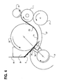
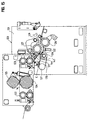
- a surface rewinder includes a conventional three roll winding cradle which includes a first or upper winding roll 20, a second or lower winding roll 21, and a rider roll 22.
- the rolls rotate in the direction of the arrows to wind a web W on a hollow cardboard core C to form a log L of convolutely wound paper such as bathroom tissue or paper toweling.
- the web is advanced in a downstream direction as indicated by the arrow A and is preferably transversely perforated along longitudinally spaced lines of perforation to form individual sheets.
- the first winding roll 20 preferably has a uniform outer surface with a high coefficient of friction so that the web does not slip on the rotating roll.
- the surface can be formed from 600 RA tungsten carbide which extends over the entire surface of the roll which engages the web. The first winding roll rotates at web speed.
- the second winding roll 21 can be movably mounted on the rewinder so that the roll can move toward and away from the first winding roll as described in U.S. Patent Nos. 4,828,195 and 4,909,452.
- the second winding roll can also have a variable speed profile as described in U.S. Patent No. 5,370,335.
- the rider roll 22 is pivotably mounted so that it moves away from the second roll as the winding log builds.
- the pinch bar Before the web reaches the first winding roll 20, it travels over a stationary pinch bar 24 which is mounted adjacent the first winding roll.
- the pinch bar has a web-pinching surface 25 which has a relatively low coefficient of friction so that there is little or no drag on the web during normal winding.
- the pinch bar surface 25 was formed from smooth steel.
- a stationary plate 27 (also referred to as a transfer plate or dead plate) is mounted below the first winding roll 20 upstream of the second winding roll 21.
- the upstream end 28 of the stationary plate is spaced from the first winding roll a distance slightly greater than the diameter of the cores C.
- the spacing between the remainder of the stationary plate and the first winding roll is slightly less than the diameter of the cores so that the cores will be compressed slightly and will be rolled along the stationary plate by the rotating winding roll.
- the stationary plate preferably has a high friction surface, for example, tungsten carbide, in order to begin core rotation as soon as possible.
- a pinch arm 30 is mounted on a rotatable shaft 31. Either a single pinch arm or a plurality of axially spaced pinch arms can be mounted on the shaft 31.
- the pinch arm includes a core-engaging surface 32 and a pinch pad 33.
- the pinch pad is preferably formed from compliant, compressible, resilient, high friction material such as 40 Shore A rubber or polyurethane. The pad may also have a high durometer surface on a low durometer base to decrease wear.
- Figure 1 illustrates the pinch arm in the process of advancing a core C along an arcuate core guide 35 toward the first winding roll 20 and the stationary plate 27. Circumferential rings of adhesive have already been applied to the core in the conventional manner.
- the pinch arm 30 and shaft 31 may be provided with a vacuum port 36 for holding the core against the pinch arm.
- Figure 2 illustrates the pinch arm moving the core into the space between the upstream end 28 of the stationary plate and the first winding roll 20.
- the pinch pad has accelerated to about one-half of web speed.
- the core travels close to the web but does not pinch the web.
- the pinch pad 33 has not yet engaged the web, and the web continues to be wound on the log L.
- FIG 3 illustrates the start of web pinch.
- the perforation P 1 which forms the last sheet to be wound on the log L in order to give a desired exact sheet count is represented by a hash mark and is located on the first winding roll just downstream of the core C.
- the previous perforation P 2 is also on the surface of the first winding roll.
- the pinch pad 33 begins to pinch the web W against the stationary pinch surface of the pinch bar 24.
- Figure 5 illustrates the end of web pinch, and the pinch pad 33 is moving out of contact with the pinch bar 24.
- the web is preferably pinched for about 1/2 inch of web travel on the first winding roll. At a web speed of 3000 feet per minute, the duration of web pinch is about 0.0016 seconds. About 1/2 inch of elongation or stretch is imparted to the web between the pinch pad and the perforation P 1 which has been severed.
- the core C has been moved by the pinch arm along the stationary plate 27 to a position in which it is compressed by the first winding roll and begins to roll on the stationary plate. A high friction surface on the stationary plate will minimize slipping of the core and will ensure that the core begins rolling as soon as possible.
- the profile of the stationary plate is preferably such that the core will be pressed against the web and the first winding roll immediately after the web is severed.
- the core has rolled farther along the stationary plate 27, and the leading portion 38 of the web folds back on the outside of the transferred web.
- the length of the foldback is determined by the position of the perforation P 1 at the time of transfer of the web to the glued core.
- the core continues to roll on the stationary plate and wind the web therearound to begin a new log.
- the log is wound between the first and second winding rolls and is eventually contacted by the rider roll 22.
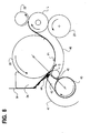
- a modified pinch arm 42 is illustrated in Figure 8.
- a plurality of axially spaced pinch arms extend from a rotatable shaft 43, and a compliant, high friction pinch pad 44 is mounted on each pinch arm.
- a core-engaging surface 45 on each pinch arm advances a core C onto a stationary plate 46 as the pinch pad approaches the pinch bar 24.
- the pinch arms extend through slots in the core guide 47, and the pinch pads pinch the web against the stationary pinch bar to tension and sever the web at perforation P 1 .
- the severed web is transferred to the core as the core begins to roll on the stationary plate, and the web is picked up by the glue on the core.
- a new core C is held in a cradle-shaped spring retainer 50 at the upstream end of stationary plate 51.
- a plurality of axially spaced pinch arms 52 are mounted on shaft 53 and pass through slots in the retainer to push the core onto the stationary plate. The core flexes the end of the spring retainer downwardly as it exits the spring retainer.
- a pinch pad 54 on each pinch arm pinches the web against stationary pinch bar 24 to sever the web at perforation P 1 .
- the severed web is picked up by an axial glue line 55 on the core.
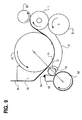
- Figure 10 illustrates a pinch arm 58 which is similar to the pinch arm of Figure 9. However, the spring retainer is omitted, and the core is advanced by the pinch arm along a core guide 59 to a stationary plate 60. A pinch pad 61 pinches the web against pinch bar 24 before the core contacts the web on the first winding roll 20.
- the pinch arm to insert the core between the stationary plate and the first winding roll facilitates the proper timing between the severance of the web and the contact of the core with the web and simplifies the structure of the core insertion device.
- the core can be inserted by a conveyor, a pusher, or other equivalent devices.
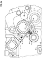
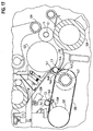
- Figure 11 illustrates a complete rewinder apparatus 65 which is designed to wind the web on recycled, mandrels rather than cores.
- the mandrels can be either solid or hollow. In one embodiment, tubular steel mandrels were used. Solid plastic mandrels could also be used.
- U.S. Patent No. 5,421,536 describes an apparatus for winding and recycling mandrels.
- the rewinder 65 includes a frame 66 on which two pairs of draw rolls 67 and 68 are mounted.
- the draw rolls advance web W through a perforator 69 to a three roll winding cradle formed by a first winding roll 70, a second winding roll 71, and a rider roll 72.
- the perforator 69 includes a rotating perforator roll 75 and a knife bar or anvil 76 for forming longitudinally spaced transverse lines of perforation in the web.
- the first winding roll includes a compliant, compressible, resilient outer layer 73 which has a relatively high coefficient of friction.
- the outer layer can be formed from tape which is wrapped around the roll or from rubber or polyurethane.
- the second winding roll 71 has a smooth outer surface, and the rider roll 72 has a rough surface with a high coefficient of friction.
- the first winding roll is rotatably mounted in the frame on a fixed axis.
- the second winding roll 71 is mounted on a pivot arm 77, and the rider roll 72 is mounted on a pivot arm 78.
- a log L is being wound on a mandrel M 1 .
- the web travels from the draw rolls 68 over a pinch bar 80 which is mounted on the frame upstream of the first winding roll 70.
- the pinch bar has a smooth, low friction surface. If desired, the pinch bar can be positioned so that the web does not contact the pinch bar during normal winding.
- a curved stationary plate 82 is mounted below the first winding roll 70 on a bar 83 on the frame.
- the stationary plate includes an upstream portion 84 on which is mounted a pad 85 (Figs. 13 and 14) and axially spaced fingers 86 which extend into grooves 87 in the second winding roll.
- the pad 85 is formed from compliant, compressible, resilient material such as smooth rubber or smooth polyurethane. It may be advantageous if the surface of the pad 85 has a relatively high coefficient of friction for initiating core rotation.
- the fingers 86 have a smooth surface.
- a pinch arm 90 is mounted on a shaft 91 which is rotatably mounted on the frame.
- a pinch pad 92 is mounted on the pinch arm and extends beyond the end of the pinch arm.
- the pinch pad is formed from compliant, compressible, resilient high friction material such as rubber or polyurethane.
- upper and lower sprockets 94 and 95 are rotatably mounted on the frame, and a chain 96 is driven by the sprockets.
- a plurality of mandrel carriers 98 are mounted on the chain 96 for picking up mandrels M from a mandrel conveyor 99 and for transporting the mandrels past a transfer glue applicator 101 to a mandrel insertion position at the upstream end of the stationary plate 82 (Fig. 13).
- Each mandrel carrier includes a pair of pivoting jaws 102 and 103 (Fig. 13) for holding a mandrel.
- the glue applicator 101 includes a pivoting arm 105 (Fig. 12) which is dipped into a bath of transfer adhesive 106 and applies an axial line of transfer adhesive to the mandrel.
- the adhesive is a relatively low tack adhesive so that the mandrel can be stripped from the wound log, but the adhesive has sufficient tack to transfer the web to the mandrel.
- the mandrel carrier deposits a glued mandrel M 2 on the upstream end of the stationary plate 82 where it is held by a mandrel retainer spring 108 which is mounted on the stationary plate.
- the mandrel does not contact the web when it is held by the retainer spring.
- the glue line on the mandrel is positioned at about 12:00 o'clock in Figure 13.
- the rotation of the shaft 91 causes the pinch pad 92 to pinch the web against the stationary pinch bar 80.
- the pinch pad is moving in the same direction as the web, the pinch pad is moving at a slower speed than the web, preferably at about 1/2 of web speed. The web is therefore slowed down by the pinch pad.
- the pinch pad continues to pinch the web as the pinch arm 90 rotates, and the web is tensioned and stretched so that it severs at the desired perforation to form a leading edge 110 as shown in Figure 13.
- Rotation of the pinch arm 90 also moves the mandrel M 2 past the retainer spring 108 (Fig. 14) so that the mandrel contacts the web and begins to roll on the stationary plate 82 under the influence of the first winding roll 70. Even though the mandrel is solid, the mandrel can be inserted between the first winding roll and the stationary plate because of the compliant layers 73 and 85. As the mandrel rolls, the line of glue on the mandrel picks up the web slightly upstream of the leading edge, and the web is transferred to the mandrel as shown in Figure 14.
- the speed of either or both of the second winding roll 71 and the rider roll 72 is changed at an appropriate time so that the winding log L moves past the lower winding roll 71 and the rider roll 72 and down the exit ramp 112.
- the mandrel is thereafter stripped from the wound log by a mandrel stripper assembly 113 ( Figure 11), and the stripped mandrel is returned by means of a chute 114 to a mandrel hopper 115 where the recycled mandrels are picked up by the mandrel carriers 98.
- the mandrel M 2 which forms the new log continues to roll over the compliant pad 85 and contacts the fingers 86.
- the web which is wrapped around the mandrel provides sufficient compliance so that the fingers need not be covered with compliant material.
- the second winding roll 71 has already begun to move away from the first winding roll 70 to permit the mandrel and the building log to roll through the nip between the two winding rolls.
- Figure 15 illustrates a complete rewinder apparatus 120 which is designed to wind the web on hollow cores C.
- the rewinder includes a frame 121 on which two pairs of draw rolls 122 and 123 are mounted.
- the draw rolls advance a web W past a rotating perforator roll 124 and a stationary knife bar 125 which form longitudinally spaced transverse lines of perforation in the web.
- a log L is being wound on a hollow core C 1 in a three roll winding cradle formed by a first winding roll 127, a second winding roll 128, and a rider roll 129.
- the first winding roll 127 rotates on a fixed axis, and the second winding roll 128 and the rider roll 129 are pivotally mounted as previously described.
- the first winding roll and the rider roll each have a rough surface with a high coefficient of friction to the web.
- the web travels from the draw rolls 123 over a pinch bar 131 which is mounted on the frame upstream of the first winding roll 127.
- the pinch bar has a smooth, low friction surface.
- a curved stationary plate 132 is mounted below the first winding roll 127 and upstream of the second winding roll 128.
- the stationary plate is formed from sheet metal and has a smooth surface.
- the stationary plate can be formed from steel with 125 micro inch finish.
- Cores are delivered to the transfer plate by a core conveyor 135 which is entrained on pulleys 136 and 137.
- a core C 2 is retained above the core conveyor by a pivoting arm 138.
- the arm 138 pivots to release the core, the core is carried to the conveyor 135 by a core support guide 139 which rotates with the pulley 137.
- a retaining bar 140 on the conveyor prevents the core from rolling as it is conveyed on the core conveyor toward the stationary plate.
- a line of adhesive 141 was previously applied to the core by an adhesive applicator.
- the conveyor 135 deposits the core on an upstream holding portion 143 of the stationary plate 132 where it is retained by a core retaining spring 144 ( Figure 17).
- Figure 17 illustrates a core C 3 in the holding position. The core C 3 does not contact the web in the holding position.
- a plurality of axially spaced pinch arms 146 are mounted on a shaft 147 which is rotatably mounted on the frame.
- a pinch pad 148 is mounted on the pinch arm and extends beyond the end of the pinch arm.
- the pinch pad is formed from compliant, compressible, resilient, high friction material of the same type which was previously described.
- the line of glue on the core picks up the web slightly upstream of the leading edge 149 of the web, the web is transferred to the core, and the leading end portion of the web folds back over the outside of the glued portion of the web portion.
- the core C 3 which begins a new log can move through the nip between the first winding roll 127 and the second winding roll 128 by moving the second winding roll away from the first winding roll and/or changing the speed of the second winding roll relative to the speed of the first winding roll.
- Figure 19 illustrates a rewinder 220 which is similar to the rewinder 120 of Figure 15 but which includes a modified core delivery mechanism.
- the reference numerals for the parts of rewinder 220 which are similar to the parts of rewinder 120 will be increased by 100.
- a core conveyor 235 is entrained on pulleys 236 and 237.
- the conveyor is inclined upwardly and extends past top and bottom core infeed wheels 251 and 252 (see also Figures 20 and 21).
- the core infeed wheels rotate to move a core C axially into a position where it is adjacent the conveyor 235 and is supported by a stationary core support 253 which is mounted on frame 221.
- the conveyor 235 can be provided by a plurality of axially spaced belts, and the core support 253 can be provided by a plurality of fingers which extend through the spaces between adjacent belts and which are supported by a mounting plate 254 on the frame of the rewinder.
- the core infeed wheels 251 and 252 are driven by pulleys 255 and 256 which are driven by a belt 257 which extends around a drive pulley 258.
- a glue applicator 259 applies an axial strip of glue 259 (Fig. 20) on the core.
- the pivotable arms 260 are mounted on a pivot pin 261 and are pivoted by a reciprocable ram 262.
- the arms 260 are mounted between the conveyor belts.
- a plurality of core pushers or guides 264 are mounted on each of the conveyor belts 235 for movement with the conveyor belts, and one or more pins 265 are mounted on each core pusher.
- the conveyor belts advance the core pushers 264 upwardly toward the core C which is held between the core supports 253 and the pivot arms 260, the pins 265 on the core pushers engage and pierce the core.
- the pivot arms 260 are then pivoted to release the core, and the core pushers 264 carry the core upwardly toward the core insertion position illustrated in Figure 20 between the stationary plate 232 and the first winding roll 227.
- the conveyor belts 235 dwell so that the core C is held at the insertion point by the pins 265.
- the pins hold the core in the correct position and orientation so that the glue line 259 is maintained in the proper position to engage the web immediately after the core contacts the web.
- the shaft 247 is rotated to move the pinch arm 246 and the pinch pad 248 into position to pinch the web against the pinch plate 231.
- Continued rotation of the pinch arm 246 causes the pinch arm to engage the core C and move the core away from the pins 265 and into the nip between the first winding roll 227 and the stationary plate 232.
- the invention can be used to wind a web on either a hollow paper core, a recycled mandrel, or other type of "center member".
- the timing of the devices for introducing the cores or mandrels to the stationary plate and the timing and speed of the rotating pinch arms can be accurately controlled in a manner well known in the art by microprocessors and servo motors.
- the timing of the web pinch can be precisely controlled so that the web is severed at the desired perforation to give each log an exact sheet count.
- the duration of the pinch can also be accurately controlled to provide minimal slack. Minimizing slack improves transfer, foldback of the web, and decreases wrinkling.
- the relative speed difference between the pinch pad and the first winding roll stretches the web and causes web separation.
- the high friction pinch pad pinches the web against a low friction pinch bar.
- the speed difference must be great enough over the duration of pinch to overcome the stretch limit of the web. This will limit the uppermost speed at which the pinch pad and core insertion operate relative to web speed.
- the surface speed of the pinch pad can be within the range of 10% to 80% of web speed.
- the high friction surface could be a resilient material (such as polyurethane) in a narrow strip, e.g., 1/4 inch wide in the machine direction.
- the pinch duration could be made very short by the speed of the pinch pad and the width of the friction strip on the pinch bar.
- the core or mandrel could be made to contact the web and winding roll immediately after the pinch to minimize the slack in the leading edge of the web.
- the surface speed of the pinch pad could be between 50% and 120% of web speed.
- the advantage would be to have the insert speed of the core be equal to the web speed at the point where they first contact at the surface of the first winding roll.
- the core would then drop in translation speed and pick up rotational speed as it came under the influence of the transfer plate and the first winding roll.
- the work required to change the motion of the core would come from the friction between the transfer plate and the core, on the opposite side of the core from where web transfer is taking place. This would optimize the transfer condition and further help to reduce any slack in the incoming web due to slip between winding roll and core.
- any change in core speed that will need to be caused by the first winding roll will be limited by the stress that the web nipped between them can tolerate. Any energy added to the core by the winding roll will be accompanied by some slip between them until they match speed. This could result in rips in the first sheet at transfer.
- the terms "low friction” and “high friction” as applied to the pinch pad, pinch bar, and upper winding roll are relative terms but are well understood by those skilled in the art. A quantitative value for the friction is not necessary for those skilled in the art, and indeed, quantitative values are difficult to measure because of differences in webs. What is important is that there by a difference in friction between the pinch pad and the pinch bar so that the higher friction surface controls the web.
- the high friction surface should have a friction which is greater than twice the friction of the low friction surface.
- the low friction surface can have a coefficient of friction within the range of about 0.01 to 0.5, and the high friction surface can have a coefficient of friction within the range of about 0.5 to 0.8.
Applications Claiming Priority (2)
| Application Number | Priority Date | Filing Date | Title |
|---|---|---|---|
| US09/204,906 US6056229A (en) | 1998-12-03 | 1998-12-03 | Surface winder with pinch cutoff |
| US204906 | 1998-12-03 |
Publications (3)
| Publication Number | Publication Date |
|---|---|
| EP1006066A2 true EP1006066A2 (fr) | 2000-06-07 |
| EP1006066A3 EP1006066A3 (fr) | 2001-05-02 |
| EP1006066B1 EP1006066B1 (fr) | 2004-08-18 |
Family
ID=22759977
Family Applications (1)
| Application Number | Title | Priority Date | Filing Date |
|---|---|---|---|
| EP99122791A Expired - Lifetime EP1006066B1 (fr) | 1998-12-03 | 1999-11-16 | Enrouleur de surface avec dispositif de coupe par pincement |
Country Status (7)
| Country | Link |
|---|---|
| US (3) | US6056229A (fr) |
| EP (1) | EP1006066B1 (fr) |
| JP (1) | JP2000169007A (fr) |
| BR (1) | BR9915719A (fr) |
| CA (1) | CA2289161C (fr) |
| DE (2) | DE69919493T2 (fr) |
| ES (1) | ES2226266T3 (fr) |
Cited By (15)
| Publication number | Priority date | Publication date | Assignee | Title |
|---|---|---|---|---|
| EP1262434A2 (fr) * | 2001-06-01 | 2002-12-04 | Giovanni Gambini | Dispositif pour ré-enrouler et former un rouleau de papier dans une enrouleuse |
| WO2004005173A1 (fr) * | 2002-07-08 | 2004-01-15 | Fabio Perini | Reenrouleur et procede de production de rouleaux de papier de tailles diverses |
| WO2004035441A1 (fr) * | 2002-10-16 | 2004-04-29 | Fabio Perini S.P.A. | Procede de production de rouleaux de matiere bande continue et bobineuse mettant en oeuvre le procede |
| WO2004106201A1 (fr) * | 2003-05-30 | 2004-12-09 | Fabio Perini S.P.A. | Machine de rembobinage peripherique a cylindre enrouleur souple |
| GR1004958B (el) * | 2002-12-03 | 2005-08-03 | Fabio Perini S.P.A. | Βελτιωμενο μηχανημα επανατυλιξης για την παραγωγη ρολων μεμβρανωδους υλικου |
| US7404529B2 (en) | 2002-07-09 | 2008-07-29 | Fabio Perini S.P.A. | Rewinding machine for producing logs of wound web material and relative method |
| US7909282B2 (en) | 2002-02-28 | 2011-03-22 | Kimberly-Clark Worldwide, Inc. | Center/surface rewinder and winder |
| US8042761B2 (en) | 2002-02-28 | 2011-10-25 | Kimberly-Clark Worldwide, Inc. | Center/surface rewinder and winder |
| US8262011B2 (en) | 2002-02-28 | 2012-09-11 | Kimberly-Clark Worldwide, Inc. | Center/surface rewinder and winder |
| US8364290B2 (en) | 2010-03-30 | 2013-01-29 | Kimberly-Clark Worldwide, Inc. | Asynchronous control of machine motion |
| US8535780B2 (en) | 2009-10-06 | 2013-09-17 | Kimberly-Clark Worldwide, Inc. | Coreless tissue rolls and method of making the same |
| US8714472B2 (en) | 2010-03-30 | 2014-05-06 | Kimberly-Clark Worldwide, Inc. | Winder registration and inspection system |
| US8757533B2 (en) | 2002-02-28 | 2014-06-24 | Kimberly-Clark Worldwide, Inc. | Center/surface rewinder and winder |
| CN104291138A (zh) * | 2013-07-16 | 2015-01-21 | 佛山市宝索机械制造有限公司 | 缩短纸头余量的复卷机 |
| WO2018192677A1 (fr) | 2017-04-17 | 2018-10-25 | Entex Rust & Mitschke Gmbh | Refroidissement lors de l'extrusion de matières fondues |
Families Citing this family (57)
| Publication number | Priority date | Publication date | Assignee | Title |
|---|---|---|---|---|
| US6056229A (en) * | 1998-12-03 | 2000-05-02 | Paper Converting Machine Co. | Surface winder with pinch cutoff |
| US6308909B1 (en) | 1999-02-09 | 2001-10-30 | The Procter & Gamble Company | Web rewinder chop-off and transfer assembly |
| US6659387B2 (en) | 2000-11-07 | 2003-12-09 | Paper Converting Machine Co. | Peripheral rewinding machine and method for producing logs of web material |
| US6422501B1 (en) | 2000-11-27 | 2002-07-23 | Paper Converting Machine Company | Core infeed apparatus for winder |
| US6532851B2 (en) | 2000-12-21 | 2003-03-18 | Paper Converting Machine Company | Apparatus for supporting product during cutting |
| IT249984Y1 (it) * | 2000-12-27 | 2003-07-07 | Gambini Giovanni | Dispositivo di ribobinatura per formare un rotolo di carta in unamacchina ribobinatrice |
| US6595459B2 (en) * | 2001-01-30 | 2003-07-22 | Kimberly-Clark Worldwide, Inc. | Apparatus and process for winding webbed material upon cores |
| EP1232980B1 (fr) * | 2001-02-16 | 2006-05-10 | M T C - Macchine Trasformazione Carta S.r.l. | Méthode pour alimenter des noyaux dans une machine à produire des rouleaux de matériau en feuille |
| US7101587B2 (en) * | 2001-07-06 | 2006-09-05 | Kimberly-Clark Worldwide, Inc. | Method for wetting and winding a substrate |
| US6649262B2 (en) | 2001-07-06 | 2003-11-18 | Kimberly-Clark Worldwide, Inc. | Wet roll having uniform composition distribution |
| US6729572B2 (en) | 2001-10-31 | 2004-05-04 | Kimberly-Clark Worldwide, Inc. | Mandrelless center/surface rewinder and winder |
| US20030113458A1 (en) * | 2001-12-18 | 2003-06-19 | Kimberly Clark Worldwide, Inc. | Method for increasing absorption rate of aqueous solution into a basesheet |
| US6851642B2 (en) | 2001-12-19 | 2005-02-08 | Kimberly-Clark Worldwide, Inc. | Apparatus for web cut-off in a rewinder |
| US7000864B2 (en) | 2002-06-10 | 2006-02-21 | The Procter & Gamble Company | Consumer product winding control and adjustment |
| US6877689B2 (en) * | 2002-09-27 | 2005-04-12 | C.G. Bretting Mfg. Co., Inc. | Rewinder apparatus and method |
| ITFI20020227A1 (it) * | 2002-11-20 | 2004-05-21 | Perini Fabio Spa | Macchina ribobinatrice con un dispositivo incollatore per incollare il lembo finale del rotolo formato e relativo metodo di avvolgimento |
| ITMI20030485U1 (it) * | 2003-10-17 | 2005-04-18 | Paper Converting Machine Co | Dispositivo di uscita log per ribobinatrice |
| JP4696073B2 (ja) * | 2003-12-05 | 2011-06-08 | フアビオ・ペリニ・ソシエタ・ペル・アチオーニ | ウエブ材料のログの製造方法及びその機械 |
| ITFI20030311A1 (it) * | 2003-12-05 | 2005-06-06 | Perini Fabio Spa | Macchina ribobinatrice, metodo per la produzione di |
| ITMI20040205A1 (it) * | 2004-02-10 | 2004-05-10 | Paper Converting Machine Co | Dispositivo di incollaggio anime di una macchina ribobinatrice e relativo metodo |
| US7222813B2 (en) | 2005-03-16 | 2007-05-29 | Chan Li Machinery Co., Ltd. | Multiprocessing apparatus for forming logs of web material and log manufacture process |
| US7905287B2 (en) | 2005-04-19 | 2011-03-15 | Halliburton Energy Services Inc. | Methods of using a polymeric precipitate to reduce the loss of fluid to a subterranean formation |
| US7943555B2 (en) | 2005-04-19 | 2011-05-17 | Halliburton Energy Services Inc. | Wellbore treatment kits for forming a polymeric precipitate to reduce the loss of fluid to a subterranean formation |
| ITFI20050108A1 (it) * | 2005-05-23 | 2006-11-24 | Perini Fabio Spa | Macchina ribobinatrice e metodo per la produzione di rotoli di materiale nastriforme |
| US7833945B2 (en) | 2005-07-15 | 2010-11-16 | Halliburton Energy Services Inc. | Treatment fluids with improved shale inhibition and methods of use in subterranean operations |
| US8455404B2 (en) | 2005-07-15 | 2013-06-04 | Halliburton Energy Services, Inc. | Treatment fluids with improved shale inhibition and methods of use in subterranean operations |
| US7392961B2 (en) * | 2005-08-31 | 2008-07-01 | The Procter & Gamble Company | Hybrid winder |
| US7455260B2 (en) * | 2005-08-31 | 2008-11-25 | The Procter & Gamble Company | Process for winding a web material |
| US20070075176A1 (en) * | 2005-10-05 | 2007-04-05 | Koch Cellulose, Llc | Article, apparatus and method for attachment of a roll of web material to a treated core |
| US8800908B2 (en) * | 2005-11-04 | 2014-08-12 | The Procter & Gamble Company | Rewind system |
| US7546970B2 (en) * | 2005-11-04 | 2009-06-16 | The Procter & Gamble Company | Process for winding a web material |
| US8459586B2 (en) * | 2006-03-17 | 2013-06-11 | The Procter & Gamble Company | Process for rewinding a web material |
| US7559503B2 (en) * | 2006-03-17 | 2009-07-14 | The Procter & Gamble Company | Apparatus for rewinding web materials |
| TW200740679A (en) * | 2006-04-21 | 2007-11-01 | Chan Li Machinery Co Ltd | Paper rolling device of roll paper |
| CN101088895B (zh) * | 2006-06-16 | 2010-05-12 | 全利机械股份有限公司 | 滚筒式纸卷的纸张卷滚装置 |
| EP1982939B1 (fr) * | 2007-04-17 | 2013-07-24 | Chan Li Machinery Co., Ltd. | Machine de renvideur de matériau de toile |
| ITMI20070900A1 (it) * | 2007-05-04 | 2008-11-05 | Giovanni Gambini | Macchina ribobinatrice perfezionata per la ribobinatura e la formazione di un rotolo di carta |
| IT1390602B1 (it) * | 2008-07-10 | 2011-09-09 | Biagiotti | Apparato, e relativo metodo, per la trasformazione di materiale nastriforme. |
| IT1392403B1 (it) * | 2008-12-23 | 2012-03-02 | Gambini Int Sa | Gruppo e metodo perfezionato di avvolgimento di carta attorno ad un'anima per realizzare un rotolo di carta |
| TWI396657B (zh) * | 2009-05-22 | 2013-05-21 | Chan Li Machinery Co Ltd | Thin paper winding device with planetary wheel breaking mechanism and its method of dialing tissue paper |
| US8157200B2 (en) * | 2009-07-24 | 2012-04-17 | The Procter & Gamble Company | Process for winding a web material |
| US8162251B2 (en) * | 2009-07-24 | 2012-04-24 | The Procter & Gamble Company | Hybrid winder |
| IT1398260B1 (it) * | 2010-02-23 | 2013-02-22 | Perini Fabio Spa | Macchina ribobinatrice e relativo metodo di avvolgimento. |
| US9284147B2 (en) | 2012-09-21 | 2016-03-15 | Paper Converting Machine Company | Method and apparatus for producing coreless rolls of paper |
| US9376281B2 (en) | 2013-09-09 | 2016-06-28 | The Procter & Gamble Company | Cam-controlled core inserter for a surface winder |
| US9352921B2 (en) | 2014-03-26 | 2016-05-31 | Kimberly-Clark Worldwide, Inc. | Method and apparatus for applying adhesive to a moving web being wound into a roll |
| US20150307315A1 (en) | 2014-04-28 | 2015-10-29 | Paper Converting Machine Company Italia Spa | Flexible winding mandrel with core segments for producing rolls of wound paper |
| WO2016057048A1 (fr) * | 2014-10-10 | 2016-04-14 | Kimberly-Clark Worldwide, Inc. | Dispositif de coupure à courte déformation |
| US9809417B2 (en) | 2015-08-14 | 2017-11-07 | The Procter & Gamble Company | Surface winder |
| US9789645B2 (en) | 2016-01-26 | 2017-10-17 | Elum Inc. | Glue delivery system |
| US10427902B2 (en) | 2016-03-04 | 2019-10-01 | The Procter & Gamble Company | Enhanced introductory portion for a surface winder |
| US10427903B2 (en) | 2016-03-04 | 2019-10-01 | The Procter & Gamble Company | Leading edge device for a surface winder |
| US10442649B2 (en) | 2016-03-04 | 2019-10-15 | The Procter & Gamble Company | Surface winder for producing logs of convolutely wound web materials |
| ES2940654T3 (es) | 2017-11-29 | 2023-05-10 | Paper Converting Machine Co | Rebobinadora de superficie con asistencia central y correa y tambor de enrollamiento que forman un nido de enrollamiento |
| US11247863B2 (en) | 2018-11-27 | 2022-02-15 | Paper Converting Machine Company | Flexible drive and core engagement members for a rewinding machine |
| US11208282B2 (en) * | 2018-12-06 | 2021-12-28 | Paper Converting Machine Company | Method of initiating a web winding process in a web winding system |
| US11383946B2 (en) | 2019-05-13 | 2022-07-12 | Paper Converting Machine Company | Solid roll product formed from surface rewinder with belt and winding drum forming a winding nest |
Citations (5)
| Publication number | Priority date | Publication date | Assignee | Title |
|---|---|---|---|---|
| US5137225A (en) * | 1989-07-11 | 1992-08-11 | Fabio Perini S.P.A. | Rewinding machine for the formation of rolls or logs, and winding method |
| EP0498052A1 (fr) * | 1991-02-05 | 1992-08-12 | Paper Converting Machine Company | Appareil et procédé pour fabriquer des rouleaux |
| WO1994021545A1 (fr) * | 1993-03-24 | 1994-09-29 | Fabio Perini S.P.A. | Machine a rembobiner et procede de formation de rouleaux d'une bande de matiere au moyen d'un dispositif de sectionnement de celle-ci |
| US5603467A (en) * | 1993-06-09 | 1997-02-18 | Fabio Perini S.P.A. | Rewinder for producing logs of web material, selectively with or without a winding core |
| WO1998012134A1 (fr) * | 1996-09-18 | 1998-03-26 | C.G. Bretting Manufacturing Company, Inc. | Rebobineuse de surface, avec doigts de commande du bobinage |
Family Cites Families (26)
| Publication number | Priority date | Publication date | Assignee | Title |
|---|---|---|---|---|
| US28353A (en) * | 1860-05-22 | Arrangement of coxtitter-shafts | ||
| US3179348A (en) | 1962-09-17 | 1965-04-20 | Paper Converting Machine Co | Web-winding apparatus and method |
| US3704835A (en) * | 1971-07-13 | 1972-12-05 | Arthur E Harley | Roll changing system |
| US3795221A (en) * | 1972-03-07 | 1974-03-05 | Dow Chemical Co | Applicator for controllably applying a liquid deposit to various workpieces |
| IT1165998B (it) * | 1979-09-21 | 1987-04-29 | Fabio Perini | Dispositivo avvolgitore continuo per nastri di carta ed altro nella produzione di carta igienica e manufatti analoghi |
| IT1167967B (it) * | 1981-08-26 | 1987-05-20 | Fabio Perini | Ribobinatrice ad alta velocita' per nastri di carta in specie con perforazioni trasversali |
| US4723724A (en) * | 1985-04-17 | 1988-02-09 | Paper Converting Machine | Web winding machine and method |
| US4962897A (en) * | 1986-04-01 | 1990-10-16 | Paper Converting Machine Company | Web winding machine and method |
| US4856725A (en) * | 1986-04-01 | 1989-08-15 | Paper Converting Machine Company | Web winding machine and method |
| IT1213818B (it) | 1987-09-01 | 1990-01-05 | Perini Finanziaria Spa | Attrezzatura per la distribuzione di collante su anime tubolari destinate alla formazione di bastoni o rotoli di nastro dicarta avvolta per carta igienica od altro, e per la alimentazione delle stesse alla macchina ribobinatrice |
| US4909452A (en) * | 1988-02-29 | 1990-03-20 | Paper Converting Machine Company | Surface winder and method |
| US4828195A (en) * | 1988-02-29 | 1989-05-09 | Paper Converting Machine Company | Surface winder and method |
| IT1233273B (it) * | 1989-03-30 | 1992-03-26 | Perini Finanziaria Spa | Macchina ribobinatrice per la formazione di bastoni di carta avvolta,sezionabili per formare rotolini utilizzabili |
| IT1240907B (it) * | 1991-07-16 | 1993-12-21 | Perini Fabio Spa | Metodo per la produzione di rotoli o logs di materiale nastriforme,e macchina per l'esecuzione di detto metodo |
| IT1265843B1 (it) * | 1993-02-15 | 1996-12-12 | Perini Fabio Spa | Metodo e macchina per la produzione di rotoli di materiale nastriforme e per lo strappo del materiale al termine dell'avvolgimento di ciascun |
| US5505405A (en) * | 1993-02-18 | 1996-04-09 | Paper Converting Machine Company | Surface rewinder and method having minimal drum to web slippage |
| US5370335A (en) * | 1993-02-18 | 1994-12-06 | Paper Converting Machine Company | Surface rewinder and method |
| IT1262515B (it) * | 1993-05-14 | 1996-07-02 | Perini Fabio Spa | Dispositivo per applicare un collante su un'anima di avvolgimento di un materiale nastriforme, metodo di applicazione e ribobinatrice incorporante detto dispositivo. |
| US5421536A (en) * | 1993-07-19 | 1995-06-06 | Paper Coverting Machine Company | Surface winder with recycled mandrels and method |
| RU2128617C1 (ru) * | 1994-06-16 | 1999-04-10 | Фабио Перини С.П.А. | Перемоточный станок для образования рулона ленточного материала |
| US5800652A (en) | 1995-05-09 | 1998-09-01 | Paper Converting Machine Co. | Method and apparatus for tail sealing of convolutely wound webs |
| US5643398A (en) * | 1995-05-15 | 1997-07-01 | C. G. Bretting Manufacturing Company, Inc. | Log tail sealer |
| US5820064A (en) * | 1997-03-11 | 1998-10-13 | C.G. Bretting Manufacturing Company, Inc. | Winding control finger surface rewinder with core insert finger |
| US6056229A (en) | 1998-12-03 | 2000-05-02 | Paper Converting Machine Co. | Surface winder with pinch cutoff |
| US6098557A (en) * | 1999-06-23 | 2000-08-08 | Kimberly-Clark Worldwide, Inc. | High speed method for producing pant-like garments |
| US6422501B1 (en) * | 2000-11-27 | 2002-07-23 | Paper Converting Machine Company | Core infeed apparatus for winder |
-
1998
- 1998-12-03 US US09/204,906 patent/US6056229A/en not_active Expired - Lifetime
-
1999
- 1999-11-09 CA CA002289161A patent/CA2289161C/fr not_active Expired - Fee Related
- 1999-11-16 DE DE69919493T patent/DE69919493T2/de not_active Expired - Fee Related
- 1999-11-16 EP EP99122791A patent/EP1006066B1/fr not_active Expired - Lifetime
- 1999-11-16 ES ES99122791T patent/ES2226266T3/es not_active Expired - Lifetime
- 1999-11-16 DE DE1006066T patent/DE1006066T1/de active Pending
- 1999-12-02 BR BR9915719-5A patent/BR9915719A/pt active Search and Examination
- 1999-12-03 JP JP11345293A patent/JP2000169007A/ja not_active Withdrawn
-
2000
- 2000-04-26 US US09/559,865 patent/US6497383B1/en not_active Expired - Fee Related
-
2002
- 2002-10-15 US US10/271,040 patent/US6871814B2/en not_active Expired - Lifetime
Patent Citations (6)
| Publication number | Priority date | Publication date | Assignee | Title |
|---|---|---|---|---|
| US5137225A (en) * | 1989-07-11 | 1992-08-11 | Fabio Perini S.P.A. | Rewinding machine for the formation of rolls or logs, and winding method |
| EP0498052A1 (fr) * | 1991-02-05 | 1992-08-12 | Paper Converting Machine Company | Appareil et procédé pour fabriquer des rouleaux |
| WO1994021545A1 (fr) * | 1993-03-24 | 1994-09-29 | Fabio Perini S.P.A. | Machine a rembobiner et procede de formation de rouleaux d'une bande de matiere au moyen d'un dispositif de sectionnement de celle-ci |
| EP0694020A1 (fr) * | 1993-03-24 | 1996-01-31 | Perini Fabio Spa | Machine a rembobiner et procede de formation de rouleaux d'une bande de matiere au moyen d'un dispositif de sectionnement de celle-ci |
| US5603467A (en) * | 1993-06-09 | 1997-02-18 | Fabio Perini S.P.A. | Rewinder for producing logs of web material, selectively with or without a winding core |
| WO1998012134A1 (fr) * | 1996-09-18 | 1998-03-26 | C.G. Bretting Manufacturing Company, Inc. | Rebobineuse de surface, avec doigts de commande du bobinage |
Cited By (25)
| Publication number | Priority date | Publication date | Assignee | Title |
|---|---|---|---|---|
| US6945491B2 (en) | 2001-06-01 | 2005-09-20 | Giovanni Gambini | Device for re-reeling and forming a roll of paper in a re-reeling machine |
| EP1262434A2 (fr) * | 2001-06-01 | 2002-12-04 | Giovanni Gambini | Dispositif pour ré-enrouler et former un rouleau de papier dans une enrouleuse |
| EP1262434A3 (fr) * | 2001-06-01 | 2004-04-14 | Giovanni Gambini | Dispositif pour ré-enrouler et former un rouleau de papier dans une enrouleuse |
| US7909282B2 (en) | 2002-02-28 | 2011-03-22 | Kimberly-Clark Worldwide, Inc. | Center/surface rewinder and winder |
| US8757533B2 (en) | 2002-02-28 | 2014-06-24 | Kimberly-Clark Worldwide, Inc. | Center/surface rewinder and winder |
| US8459587B2 (en) | 2002-02-28 | 2013-06-11 | Kimberly-Clark Worldwide, Inc. | Center/surface rewinder and winder |
| US8262011B2 (en) | 2002-02-28 | 2012-09-11 | Kimberly-Clark Worldwide, Inc. | Center/surface rewinder and winder |
| US8042761B2 (en) | 2002-02-28 | 2011-10-25 | Kimberly-Clark Worldwide, Inc. | Center/surface rewinder and winder |
| CN100351155C (zh) * | 2002-07-08 | 2007-11-28 | 法比奥·佩里尼 | 复卷机及生产各种尺寸卷筒纸的方法 |
| US7360738B2 (en) | 2002-07-08 | 2008-04-22 | Fabio Perini | Method for producing variously sized paper logs |
| WO2004005173A1 (fr) * | 2002-07-08 | 2004-01-15 | Fabio Perini | Reenrouleur et procede de production de rouleaux de papier de tailles diverses |
| US7175126B2 (en) | 2002-07-08 | 2007-02-13 | Fabio Perini | Rewinding machine for producing variously sized paper logs |
| US7404529B2 (en) | 2002-07-09 | 2008-07-29 | Fabio Perini S.P.A. | Rewinding machine for producing logs of wound web material and relative method |
| US7350739B2 (en) | 2002-10-16 | 2008-04-01 | Fabio Perini S.P.A. | Method for producing logs of web material and rewinding machine implementing said method |
| WO2004035441A1 (fr) * | 2002-10-16 | 2004-04-29 | Fabio Perini S.P.A. | Procede de production de rouleaux de matiere bande continue et bobineuse mettant en oeuvre le procede |
| GR1004958B (el) * | 2002-12-03 | 2005-08-03 | Fabio Perini S.P.A. | Βελτιωμενο μηχανημα επανατυλιξης για την παραγωγη ρολων μεμβρανωδους υλικου |
| WO2004106201A1 (fr) * | 2003-05-30 | 2004-12-09 | Fabio Perini S.P.A. | Machine de rembobinage peripherique a cylindre enrouleur souple |
| US8535780B2 (en) | 2009-10-06 | 2013-09-17 | Kimberly-Clark Worldwide, Inc. | Coreless tissue rolls and method of making the same |
| US9365376B2 (en) | 2009-10-06 | 2016-06-14 | Kimberly-Clark Worldwide, Inc. | Coreless tissue rolls and method of making the same |
| US8364290B2 (en) | 2010-03-30 | 2013-01-29 | Kimberly-Clark Worldwide, Inc. | Asynchronous control of machine motion |
| US8714472B2 (en) | 2010-03-30 | 2014-05-06 | Kimberly-Clark Worldwide, Inc. | Winder registration and inspection system |
| US9540202B2 (en) | 2010-03-30 | 2017-01-10 | Kimberly-Clark Worldwide, Inc. | Winder registration and inspection system |
| CN104291138A (zh) * | 2013-07-16 | 2015-01-21 | 佛山市宝索机械制造有限公司 | 缩短纸头余量的复卷机 |
| WO2018192677A1 (fr) | 2017-04-17 | 2018-10-25 | Entex Rust & Mitschke Gmbh | Refroidissement lors de l'extrusion de matières fondues |
| US11446617B2 (en) | 2017-04-17 | 2022-09-20 | Entex Rust & Mitschke Gmbh | Extruder with planetary roller section for cooling melts |
Also Published As
| Publication number | Publication date |
|---|---|
| EP1006066B1 (fr) | 2004-08-18 |
| CA2289161C (fr) | 2008-01-22 |
| BR9915719A (pt) | 2001-08-07 |
| ES2226266T3 (es) | 2005-03-16 |
| US6871814B2 (en) | 2005-03-29 |
| CA2289161A1 (fr) | 2000-06-03 |
| DE1006066T1 (de) | 2003-03-20 |
| EP1006066A3 (fr) | 2001-05-02 |
| DE69919493D1 (de) | 2004-09-23 |
| JP2000169007A (ja) | 2000-06-20 |
| DE69919493T2 (de) | 2004-12-23 |
| US6056229A (en) | 2000-05-02 |
| US6497383B1 (en) | 2002-12-24 |
| US20030037725A1 (en) | 2003-02-27 |
Similar Documents
| Publication | Publication Date | Title |
|---|---|---|
| US6056229A (en) | Surface winder with pinch cutoff | |
| US5421536A (en) | Surface winder with recycled mandrels and method | |
| RU2567202C2 (ru) | Машина для перемотки и способ производства рулонов из рулонного материала | |
| CA2115496C (fr) | Methode et machine pour produire des bobines de materiau en bande et pour couper la bande une fois la bobine terminee | |
| EP0580561B1 (fr) | Machine et procédé pour la formation de bobines sans noyau de matériau en bande | |
| CA2115497C (fr) | Enrouleuse pour produire une bobine sans noyau de materiau en bande comportant un plateau pour soutenir la bobine pendant l'enroulement | |
| US6422501B1 (en) | Core infeed apparatus for winder | |
| GB2105688A (en) | Snap-separating of web material during transfer of winding onto new core | |
| EP2964555B1 (fr) | Machine de rembobinage et procédé permettant de produire des rouleaux d'un matériau en bande | |
| RU2337051C2 (ru) | Усовершенствованный перемоточно-разрезной станок для производства рулонов бумажного рулонного материала | |
| JPH0583465B2 (fr) | ||
| US6145777A (en) | Single station continuous log roll winder | |
| PL173069B1 (pl) | Urządzenie przewijające do wytwarzania bezrdzeniowych bel materiału arkuszowego, sposób wytwarzania bezrdzeniowych bel materiału arkuszowego oraz bezrdzeniowa bela materiału arkuszowego | |
| US20020066820A1 (en) | Peripheral rewinding machine and method for producing logs of web material | |
| EP2731894B1 (fr) | Procédé et appareil pour rompre un film à l'aide d'un ensemble de coupe | |
| EP1205414B1 (fr) | Enrouleuse à entraînement péripherique et méthode pour la production de rouleaux de matériau en bande | |
| MXPA99011172A (en) | Surface winder with pinch cutoff | |
| CA2100797C (fr) | Methode et machine pour l'obtention de materiaux bobines sans ame | |
| JPH07108743B2 (ja) | ウエブの巻取り方法とその装置 |
Legal Events
| Date | Code | Title | Description |
|---|---|---|---|
| PUAI | Public reference made under article 153(3) epc to a published international application that has entered the european phase |
Free format text: ORIGINAL CODE: 0009012 |
|
| AK | Designated contracting states |
Kind code of ref document: A2 Designated state(s): DE ES FR GB IT SE |
|
| AX | Request for extension of the european patent |
Free format text: AL;LT;LV;MK;RO;SI |
|
| PUAL | Search report despatched |
Free format text: ORIGINAL CODE: 0009013 |
|
| AK | Designated contracting states |
Kind code of ref document: A3 Designated state(s): AT BE CH CY DE DK ES FI FR GB GR IE IT LI LU MC NL PT SE |
|
| AX | Request for extension of the european patent |
Free format text: AL;LT;LV;MK;RO;SI |
|
| 17P | Request for examination filed |
Effective date: 20010606 |
|
| AKX | Designation fees paid |
Free format text: DE ES FR GB IT SE |
|
| 17Q | First examination report despatched |
Effective date: 20021029 |
|
| DET | De: translation of patent claims | ||
| GRAP | Despatch of communication of intention to grant a patent |
Free format text: ORIGINAL CODE: EPIDOSNIGR1 |
|
| GRAS | Grant fee paid |
Free format text: ORIGINAL CODE: EPIDOSNIGR3 |
|
| GRAA | (expected) grant |
Free format text: ORIGINAL CODE: 0009210 |
|
| AK | Designated contracting states |
Kind code of ref document: B1 Designated state(s): DE ES FR GB IT SE |
|
| REG | Reference to a national code |
Ref country code: GB Ref legal event code: FG4D |
|
| REG | Reference to a national code |
Ref country code: SE Ref legal event code: TRGR |
|
| REF | Corresponds to: |
Ref document number: 69919493 Country of ref document: DE Date of ref document: 20040923 Kind code of ref document: P |
|
| ET | Fr: translation filed | ||
| REG | Reference to a national code |
Ref country code: ES Ref legal event code: FG2A Ref document number: 2226266 Country of ref document: ES Kind code of ref document: T3 |
|
| PLBE | No opposition filed within time limit |
Free format text: ORIGINAL CODE: 0009261 |
|
| STAA | Information on the status of an ep patent application or granted ep patent |
Free format text: STATUS: NO OPPOSITION FILED WITHIN TIME LIMIT |
|
| 26N | No opposition filed |
Effective date: 20050519 |
|
| PGFP | Annual fee paid to national office [announced via postgrant information from national office to epo] |
Ref country code: FR Payment date: 20051021 Year of fee payment: 7 |
|
| PGFP | Annual fee paid to national office [announced via postgrant information from national office to epo] |
Ref country code: GB Payment date: 20051024 Year of fee payment: 7 Ref country code: DE Payment date: 20051024 Year of fee payment: 7 |
|
| PGFP | Annual fee paid to national office [announced via postgrant information from national office to epo] |
Ref country code: SE Payment date: 20051025 Year of fee payment: 7 |
|
| PGFP | Annual fee paid to national office [announced via postgrant information from national office to epo] |
Ref country code: ES Payment date: 20051117 Year of fee payment: 7 |
|
| PG25 | Lapsed in a contracting state [announced via postgrant information from national office to epo] |
Ref country code: SE Free format text: LAPSE BECAUSE OF NON-PAYMENT OF DUE FEES Effective date: 20061117 |
|
| PG25 | Lapsed in a contracting state [announced via postgrant information from national office to epo] |
Ref country code: DE Free format text: LAPSE BECAUSE OF NON-PAYMENT OF DUE FEES Effective date: 20070601 |
|
| EUG | Se: european patent has lapsed | ||
| GBPC | Gb: european patent ceased through non-payment of renewal fee |
Effective date: 20061116 |
|
| REG | Reference to a national code |
Ref country code: FR Ref legal event code: ST Effective date: 20070731 |
|
| PG25 | Lapsed in a contracting state [announced via postgrant information from national office to epo] |
Ref country code: GB Free format text: LAPSE BECAUSE OF NON-PAYMENT OF DUE FEES Effective date: 20061116 |
|
| REG | Reference to a national code |
Ref country code: ES Ref legal event code: FD2A Effective date: 20061117 |
|
| PG25 | Lapsed in a contracting state [announced via postgrant information from national office to epo] |
Ref country code: FR Free format text: LAPSE BECAUSE OF NON-PAYMENT OF DUE FEES Effective date: 20061130 Ref country code: ES Free format text: LAPSE BECAUSE OF NON-PAYMENT OF DUE FEES Effective date: 20061117 |
|
| PGFP | Annual fee paid to national office [announced via postgrant information from national office to epo] |
Ref country code: IT Payment date: 20101027 Year of fee payment: 12 |
|
| PG25 | Lapsed in a contracting state [announced via postgrant information from national office to epo] |
Ref country code: IT Free format text: LAPSE BECAUSE OF NON-PAYMENT OF DUE FEES Effective date: 20121116 |