EP1005958A1 - Appareil de fixation de tampon par gaz comprimé - Google Patents
Appareil de fixation de tampon par gaz comprimé Download PDFInfo
- Publication number
- EP1005958A1 EP1005958A1 EP99402990A EP99402990A EP1005958A1 EP 1005958 A1 EP1005958 A1 EP 1005958A1 EP 99402990 A EP99402990 A EP 99402990A EP 99402990 A EP99402990 A EP 99402990A EP 1005958 A1 EP1005958 A1 EP 1005958A1
- Authority
- EP
- European Patent Office
- Prior art keywords
- buffer
- receiving
- shoulder
- magazine
- housing
- Prior art date
- Legal status (The legal status is an assumption and is not a legal conclusion. Google has not performed a legal analysis and makes no representation as to the accuracy of the status listed.)
- Granted
Links
Images

Classifications
-
- B—PERFORMING OPERATIONS; TRANSPORTING
- B25—HAND TOOLS; PORTABLE POWER-DRIVEN TOOLS; MANIPULATORS
- B25C—HAND-HELD NAILING OR STAPLING TOOLS; MANUALLY OPERATED PORTABLE STAPLING TOOLS
- B25C1/00—Hand-held nailing tools; Nail feeding devices
- B25C1/08—Hand-held nailing tools; Nail feeding devices operated by combustion pressure
- B25C1/10—Hand-held nailing tools; Nail feeding devices operated by combustion pressure generated by detonation of a cartridge
- B25C1/18—Details and accessories, e.g. splinter guards, spall minimisers
- B25C1/182—Feeding devices
- B25C1/184—Feeding devices for nails
-
- B—PERFORMING OPERATIONS; TRANSPORTING
- B25—HAND TOOLS; PORTABLE POWER-DRIVEN TOOLS; MANIPULATORS
- B25C—HAND-HELD NAILING OR STAPLING TOOLS; MANUALLY OPERATED PORTABLE STAPLING TOOLS
- B25C1/00—Hand-held nailing tools; Nail feeding devices
- B25C1/08—Hand-held nailing tools; Nail feeding devices operated by combustion pressure
Definitions
- the invention relates to a combustion pad fixing apparatus.
- a flammable compressed gas in particular used in the field of building to fix cable fixing bases, chutes and other such accessories.
- This type of fixing device comprises a cylinder, in which is mounted sliding a buffer propulsion piston, a combustion chamber, a housing for receiving a compressed gas cartridge, a store removable pad feeder, pad guide, block shear and a handle.
- the removable buffer supply magazine contains a strip of buffer receiving rings.
- the shear block has a buffer reception passage which communicates with the pads and extends forward through a pad guide passage of the tampon guide, intended to guide the tampon until its penetration in the support.
- the head pad of the support strip is introduced into the shear block and, after pressing the device against a support, the piston is propelled forward and strikes the buffer received in the block of shear. Under the impact of the strike, the band of reception rings of pad is sheared, the strip head pad, detached, is projected towards the front, being guided by the buffer guide, and enters the support.
- the shear block of known devices is formed in two parts, upper and lower, each providing a section groove semi-circular cross-section.
- the upper part is integral with the buffer guide and a box containing the cylinder and the combustion chamber
- the lower part is integral with the buffer supply magazine.
- the present invention aims to overcome these drawbacks.
- the invention relates to a tampon fixing device.
- a tampon fixing device comprising a removable buffer supply magazine, intended for contain a strip of buffer receiving rings, a buffer guide and a block for shearing the strip of buffer receiving rings, characterized by the fact that the shear block is functionally monobloc.
- the shear block With the fixing device of the invention, after removal from the magazine pads of the device, the shear block remains in one piece.
- the device can therefore be used with or without the buffer magazine. Thanks to this, we remove the security system prohibiting fire after removal of the stamp store.
- the device without the buffer magazine, can be used to fix a buffer in a deep profile, which would be not possible with the buffer magazine mounted on the device due to the size of the store.
- the shear block and the feed store pads are arranged to cooperate by fitting a skirt, providing a buffer supply passage in a reception housing of the skirt.
- the skirt and its receiving housing are shaped to that the nesting of one in the other is done with play.
- the buffer magazine can be very easily mounted on the device.
- the skirt is integral with the shear block.
- the latching means include a shoulder, supported by a pin mounted on means of reminder, intended to cooperate with a groove for receiving the shoulder, extended by at least one pushing finger and blocking of the shoulder.
- the front and “the rear” respectively denote the direction to which a buffer is propelled during a shot and the direction opposite.
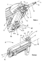
- the tampon fixing apparatus comprises a case 1, integral with a handle 5 and a housing 6 for receiving a gas cartridge tablet, a removable magazine 2 for supplying buffers, intended for contain a strip of buffer receiving rings, a buffer guide 3, a block 4 for shearing the strip of buffer receiving rings and an anti-fire security system.
- the housing 1 contains a cylinder, in which is slidably mounted a buffer propulsion piston, a combustion chamber and a battery receiving housing, not shown.
- the anti-fire safety system prohibits any firing without prior support of the device against a support.
- the buffer guide 3 and the shear block 4 extend in front of the housing 1, along a longitudinal axis 7.
- the handle 5 extends substantially perpendicular to the axis 7, here parallel to the receiving housing 6 of the compressed gas cartridge and on the back of it.
- the handle 5 and the housing 6 extend below the housing 1, in an axial plane (that is to say containing the center axis 7) of the apparatus, which will be called "plane P" thereafter.
- the shear block 4 has two parts, lower 9 and upper 10, each providing a groove of semi-circular cross section and secured to each other using screws 8, 8 '. It will be emphasized here that because that the two parts, lower 9 and upper 10, are integral with one of the other, the shear block 4 is functionally in one piece. We would have just as well could have considered a shear block made up of a single part.
- the two grooves in the lower 9 and upper 10 parts of the block shear 4 form a buffer receiving passage extending forward through a tampon guide passage through the tampon guide 3 and intended during a shot to guide the tampon to its penetration in a receiving material.
- the upper part 10 of the shear block 4 is integral, at its front end, of a buffer guide holder 13 in which is mounted sliding the buffer guide 3.
- the lower part 9 of the shear block 4 is integral with a skirt projecting external 11 providing a through passage 12 for supplying buffer in the shear block 4, which communicates with the passage of receive buffer from it.
- the rear end part of the shear block 4 is received and screwed in a receiving cradle 14, integral with the front part of the housing 1.
- the buffer store 2 contains a housing for receiving a strip of buffer receiving rings, with an upper opening 15, and a system for pushing the buffer strip towards the upper opening 15.
- the buffer strip receiving housing communicates by the upper opening 15 with a housing 16 for receiving the skirt 11 of the shear block 4.
- the magazine 2 extends along a longitudinal axis 19. Thereafter, the center plane of store 2 will be called "plane P '" containing axis 19.
- the shear block 4 and the buffer magazine 2 are intended for cooperate by fitting the skirt 11 into its receiving housing 16, the skirt 11 and its receiving housing 16 being shaped so that the nesting of one in the other is done with play.
- the buffer store 2 has a rear face 17, intended to come in look of a front face 18 of the housing 6.
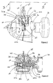
- the face 17 supports, at its lower end, a female latching part 40 intended for cooperate with a male latching part 20 secured to the end lower side 18, for fixing the buffer magazine 2 on the device.
- the male latching part 20 has a pin 21 supported by two flanges 24, 25 and itself supporting two shoulders 26a, 26b, in form of flanges.
- the two flanges 24, 25 extend generally parallel to the plane P of the device, on either side of it, and the axis 21 is perpendicular to it plane P.
- the two flanges 24, 25 are extended at the rear respectively by two fixing feet 22a, 22b, integral with the housing 6 and in support One against the other.
- the flange 25 includes a housing 27 for receiving a portion end 21a of the axis 21, projecting towards the inside of the male part 20.
- a spring 28 is in abutment, at one of its ends, against the bottom of the housing 27 is, at its other end, against the bottom of an axial cavity 29 formed in the end portion 21a.
- Axis 21 is thus mounted on a spring and movable in axial translation.
- the flange 24 includes a housing 30 for receiving the shoulder 26b, projecting towards the inside of the male part 20.
- the axis 21 is thus laterally protruding out of the flange 24 outwards.
- the part end 21b is threaded and received in a threaded hole 33 formed in a wheel 32 for driving the axis 21, and comprises two flats intended to cooperate with two conjugate dishes of the opening 31, in order to block in rotation the axis 21.
- a stop 34, intended to block in axial translation the wheel 32, is fixed on the external lateral surface of the flange 24 and has a through opening for passage of the axis 21.
- the translation of the axis 21 is limited, on the one hand, by abutment of the shoulder 26a against the edge of the housing 27 and, on the other hand, by abutment the shoulder 26b against the edge of the opening 31, located at the bottom of the housing 30.
- the housings 27 and 30 are separated from each other by a space 36 of reception of the female latching part 40, as will be explained further.
- the two fixing feet 22a, 22b form a free surface 31, extending in the vicinity and behind the axis 21 in a plane generally perpendicular to the axis 7.
- the two flanges 24, 25 provide between them a lower passage 35 for introducing the female snap-on part 40 extending upward through a passage 35 '(FIG. 6) for receiving a positioning plate 46 of the female latching part 40, formed between the surface 31 and the walls of the housings 27 and 30.
- the shoulder 26a In the rest position ( Figures 3 and 4), the shoulder 26a is arranged in the reception space 36, at the right of the introduction passage 35.
- the shoulder 26b extends to the bottom of its receiving housing 30 and the wheel 32, unscrewed, is moved away from the stop 34.
- the female latching part 40 has a groove 41 for receiving the shoulder 26a, extending in the plane P ', extended upwards by two fingers, rear 42 and front 43, symmetrical, pushing and locking the shoulder 26a, as will be explained later.
- the front finger 43 is adjacent to the surface 17 and the rear finger 42 is moved away from it, towards the rear.
- the fingers 42, 43 tighten towards each other from their ends respective connection with the groove 41 towards their free ends, separated from each other by a distance slightly greater than the diameter of the axis 21.
- the groove 41 has an internal wall for receiving the shoulder 26a, of semi-circular shape in longitudinal section in the plane P ', oriented towards the upper part of the store 2.
- the internal walls of the fingers 42, 43 extend the internal wall of the groove 41, the internal wall overall having a circular shape in longitudinal section (parallel to the plane P '), of diameter substantially greater than that of the shoulder 26a, with an opening for the passage of the axis 21.
- the fingers 42, 43 are thus intended to block the shoulder 26a in its groove reception 41.
- Each finger 42 (43) comprises a right external lateral face 44a, parallel to the plane P ', and another external lateral face 44b inclined by relative to the plane P ', the width of the finger 42 (43) narrowing from its end of connection with the groove 41 towards its free end.
- the faces inclined 44b thus shaped into corners, function as surfaces of thrust intended to push the shoulder 26a laterally when the introduction of the male latching part 20 into the female part latching 40, as will be explained later.
- the section of the lateral opening 47 of the female latching part 40 in the plane of the right lateral face 44a is narrowed, less than the section transverse of the shoulder 26a but slightly greater than the section transverse of axis 21.
- the rear finger 42 supports the positioning plate 46 extending perpendicular to the plane P 'and parallel to the longitudinal axis 19.
- a fixing arm 45 is integral with the female latching part 40, and extends in the longitudinal plane P ', downwards, opposite the fingers 42, 43.
- the fixing arm 45 is received in a slot made in a projection 48 secured to the lower end portion of the surface 17 and screwed to this projection 48.
- the width of the groove 41, perpendicular to the longitudinal plane P ', is substantially less than the distance separating the two housings 27 and 30, in other words to the width of space 36, and slightly greater than the width of the shoulder 26a.
- An operator first indexes the buffer store 2 with respect to the fixing device by positioning the skirt 11 in front of its housing reception 16 and the female latching part 40 in the lower passage introduction 35 of the male latching part 20.
- the positioning plate 46 When the female snap-in part 40 is introduced into the part latching male 20, the positioning plate 46 is received and blocked in its receiving passage 32. Furthermore, the thrust surfaces 44b pushing fingers 42, 43 laterally push the shoulder 26a, against the return action of the spring 28, until the receiving groove 41 comes substantially to the right of the shoulder 26a. It then enters in the receiving groove 21, under the pushing action of the spring 28, and abuts against the inner edge of the narrowed side opening 47. In this position, the fingers 42, 43 block, retain the shoulder 26a in the receiving groove 41.
- the tape head buffer is introduced into the buffer receiving passage of the shear block 4, via the feed passage 12, under the pushing action of the pushing system of magazine 2.
- the operator sets up press the device against this support.
- the operator causes the case 1 to move forward, integral with the block of shear 4 and of the buffer guide holder 13, relative to the buffer guide 3 the free end of which bears against the support.
- the support causes the combustion chamber to close, in which gas tablet is injected, and unlocking the anti-fire security system.
- the operator starts the firing, in order to explode the gas tablet contained in the combustion chamber.
- the piston is then propelled forward and strikes the buffer received in the passage of receiving the shear block 4. Under the action of striking, the strip of rings are sheared and the buffer, detached, is thrown forward and guided through the guide passage of the buffer guide until it enters the support.
- the fixing device can be used to fix a buffer pre-mounted on a part to be fixed, or to fix a buffer in a deep profile.
- a shutter could be provided to seal the buffer feed passage from the shear block skirt after removal from the stamp store.
Abstract
Description
- la figure 1 représente une vue en perspective partielle de l'appareil de fixation sans magasin de tampons;
- la figure 2 représente une vue en perspective du magasin de tampons de l'appareil de la figure 1;
- la figure 3 représente une vue en perspective d'un système d'encliquetage pour la fixation et le verrouillage du magasin de tampons de la figure 2 sur l'appareil de la figure 1, juste avant fixation;
- la figure 4 représente une vue en coupe du système d'encliquetage de la figure 3, le long de la ligne IV-IV;
- la figure 5 représente une vue en coupe du système d'encliquetage de la figure 3, après fixation et avant verrouillage, le long de la ligne IV-IV;
- la figure 6 représente une vue en coupe du système d'encliquetage de la figure 3, après fixation et avant verrouillage, le long de la ligne VI-VI;
- la figure 7 représente une vue en coupe du système d'encliquetage de la figure 3, après verrouillage, le long de la ligne IV-IV et
- la figure 8 représente une vue en coupe du système d'encliquetage de la figure 3, après déverrouillage, le long de la ligne IV-IV.
Claims (9)
- Appareil de fixation de tampon comprenant un magasin amovible (2) d'alimentation en tampons, destiné à contenir une bande de bagues de réception de tampon, un guide-tampon (3) et un bloc (4) de cisaillement de la bande de bagues de réception de tampon, caractérisé par le fait que le bloc de cisaillement (4) est fonctionnellement monobloc.
- Appareil selon la revendication 1, dans lequel le bloc de cisaillement (4) et le magasin (2) d'alimentation en tampons sont agencés pour coopérer par emboítement d'une jupe (11), ménageant un passage (12) d'amenée de tampon, dans un logement (16) de réception de la jupe (11).
- Appareil selon la revendication 2, dans lequel la jupe (11) et son logement de réception (16) sont conformés pour que l'emboítement de l'un dans l'autre s'effectue avec du jeu.
- Appareil selon l'une des revendications 1 à 3, dans lequel la jupe (11) est solidaire du bloc de cisaillement (4).
- Appareil selon l'une des revendications 1 à 4, dans lequel il est prévu des moyens d'encliquetage pour la fixation du magasin (2) d'alimentation en tampons sur l'appareil.
- Appareil selon la revendication 5, dans lequel les moyens d'encliquetage comprennent un épaulement (26a), supporté par un axe (21) monté sur des moyens de rappel (28), destiné à coopérer avec une gorge (41) de réception de l'épaulement (26a), prolongée par au moins un doigt (42, 43) de poussée et de blocage de l'épaulement (26a).
- Appareil selon la revendication 6, dans lequel il est prévu des moyens (32, 34) pour empêcher l'entraínement en déplacement de l'axe (21) afin de verrouiller l'épaulement (26a) dans la gorge de réception (41).
- Appareil selon l'une des revendications 1 à 7, dans lequel il est prévu un berceau (14) de réception d'une partie d'extrémité arrière du bloc de cisaillement (4).
- Appareil selon l'une des revendications 1 à 8, dans lequel le guide-tampon (3) est monté coulissant par rapport au bloc de cisaillement (4).
Priority Applications (1)
| Application Number | Priority Date | Filing Date | Title |
|---|---|---|---|
| DK99402990T DK1005958T3 (da) | 1998-12-04 | 1999-12-01 | Apparat til fastgörelse af rawplugs ved hjælp af trykluft |
Applications Claiming Priority (2)
| Application Number | Priority Date | Filing Date | Title |
|---|---|---|---|
| FR9815341 | 1998-12-04 | ||
| FR9815341A FR2786722B1 (fr) | 1998-12-04 | 1998-12-04 | Appareil de fixation de tampon par gaz comprime |
Publications (2)
| Publication Number | Publication Date |
|---|---|
| EP1005958A1 true EP1005958A1 (fr) | 2000-06-07 |
| EP1005958B1 EP1005958B1 (fr) | 2004-06-09 |
Family
ID=9533596
Family Applications (1)
| Application Number | Title | Priority Date | Filing Date |
|---|---|---|---|
| EP99402990A Expired - Lifetime EP1005958B1 (fr) | 1998-12-04 | 1999-12-01 | Appareil de fixation de tampon par gaz comprimé |
Country Status (11)
| Country | Link |
|---|---|
| US (1) | US6454152B1 (fr) |
| EP (1) | EP1005958B1 (fr) |
| AT (1) | ATE268672T1 (fr) |
| AU (1) | AU730883B2 (fr) |
| CA (1) | CA2291711C (fr) |
| DE (1) | DE69917868T2 (fr) |
| DK (1) | DK1005958T3 (fr) |
| ES (1) | ES2223161T3 (fr) |
| FR (1) | FR2786722B1 (fr) |
| NZ (1) | NZ501469A (fr) |
| PT (1) | PT1005958E (fr) |
Cited By (1)
| Publication number | Priority date | Publication date | Assignee | Title |
|---|---|---|---|---|
| EP1375075A2 (fr) * | 2002-06-24 | 2004-01-02 | Illinois Tool Works, Inc. | Dispositif d'alimentation d'éléments de fixation et mécanisme de positionnement pour un outil |
Families Citing this family (6)
| Publication number | Priority date | Publication date | Assignee | Title |
|---|---|---|---|---|
| AU742745B2 (en) * | 1998-12-04 | 2002-01-10 | Societe De Prospection Et D'inventions Techniques S.P.I.T. | Fastener fixing apparatus |
| DE10356548B4 (de) * | 2003-12-04 | 2006-03-16 | Hilti Ag | Magaziniervorrichtung |
| US7971768B2 (en) * | 2004-05-04 | 2011-07-05 | Illinois Tool Works Inc. | Guidance system for fasteners |
| EP2099587B1 (fr) * | 2006-11-09 | 2016-02-10 | Stanely Fastening Systems, L.P. | Dispositif d'entraînement d'éléments de fixation sans fil |
| FR2993810B1 (fr) * | 2012-07-25 | 2014-07-11 | Illinois Tool Works | Outil de fixation par tir indirect, a support de detente anti-tir |
| TWI781941B (zh) * | 2016-07-29 | 2022-11-01 | 日商工機控股股份有限公司 | 釘打機 |
Citations (4)
| Publication number | Priority date | Publication date | Assignee | Title |
|---|---|---|---|---|
| FR2106135A5 (fr) * | 1970-08-28 | 1972-04-28 | Hilti Ag | |
| DE2432642A1 (de) * | 1974-07-08 | 1976-01-29 | Hilti Ag | Verfahren und geraet zum setzen eines duebels |
| US4196833A (en) * | 1978-10-10 | 1980-04-08 | Haytayan Harry M | Pneumatic tacking tool |
| EP0835726A1 (fr) * | 1996-10-14 | 1998-04-15 | HILTI Aktiengesellschaft | Outil de scellement actionné par poudre avec magasin pour éléments de fixation |
Family Cites Families (10)
| Publication number | Priority date | Publication date | Assignee | Title |
|---|---|---|---|---|
| US3920169A (en) * | 1973-09-17 | 1975-11-18 | Textron Inc | Driving tool mechanism |
| US4053094A (en) * | 1976-05-06 | 1977-10-11 | Textron, Inc. | Cartridge containing continuous wire coil and portable device for cutting successive lengths from the wire and driving the same |
| US4197974A (en) * | 1978-06-12 | 1980-04-15 | Speedfast Corporation | Nailer |
| US4597517A (en) * | 1985-06-21 | 1986-07-01 | Signode Corporation | Magazine interlock for a fastener driving device |
| US4778094A (en) * | 1987-10-02 | 1988-10-18 | The Dimpling Nailing Gun Company | Nail and dimpler driving apparatus for nailing gun |
| US4821938A (en) * | 1987-11-25 | 1989-04-18 | Haytayan Harry M | Powder-actuated fastener driving tool |
| EP0589485B1 (fr) * | 1988-04-07 | 1998-01-21 | Pittini, Alessandra | Outil de scellement pneumatique |
| DE19707235A1 (de) * | 1997-02-24 | 1998-08-27 | Hilti Ag | Setzgerät mit Magazin für Befestigungselemente |
| US5816468A (en) * | 1997-06-24 | 1998-10-06 | Testo Industries Corp. | No-idle-striking structure for nailing machines |
| US6053389A (en) * | 1998-08-05 | 2000-04-25 | Sup Drogon Enterprise Co., Ltd. | Nailing gun magazine specially designed for big nail set |
-
1998
- 1998-12-04 FR FR9815341A patent/FR2786722B1/fr not_active Expired - Fee Related
-
1999
- 1999-12-01 DK DK99402990T patent/DK1005958T3/da active
- 1999-12-01 EP EP99402990A patent/EP1005958B1/fr not_active Expired - Lifetime
- 1999-12-01 NZ NZ501469A patent/NZ501469A/xx not_active IP Right Cessation
- 1999-12-01 ES ES99402990T patent/ES2223161T3/es not_active Expired - Lifetime
- 1999-12-01 AT AT99402990T patent/ATE268672T1/de not_active IP Right Cessation
- 1999-12-01 AU AU63025/99A patent/AU730883B2/en not_active Ceased
- 1999-12-01 DE DE69917868T patent/DE69917868T2/de not_active Expired - Lifetime
- 1999-12-01 PT PT99402990T patent/PT1005958E/pt unknown
- 1999-12-03 CA CA002291711A patent/CA2291711C/fr not_active Expired - Fee Related
- 1999-12-03 US US09/453,557 patent/US6454152B1/en not_active Expired - Lifetime
Patent Citations (4)
| Publication number | Priority date | Publication date | Assignee | Title |
|---|---|---|---|---|
| FR2106135A5 (fr) * | 1970-08-28 | 1972-04-28 | Hilti Ag | |
| DE2432642A1 (de) * | 1974-07-08 | 1976-01-29 | Hilti Ag | Verfahren und geraet zum setzen eines duebels |
| US4196833A (en) * | 1978-10-10 | 1980-04-08 | Haytayan Harry M | Pneumatic tacking tool |
| EP0835726A1 (fr) * | 1996-10-14 | 1998-04-15 | HILTI Aktiengesellschaft | Outil de scellement actionné par poudre avec magasin pour éléments de fixation |
Cited By (5)
| Publication number | Priority date | Publication date | Assignee | Title |
|---|---|---|---|---|
| EP1375075A2 (fr) * | 2002-06-24 | 2004-01-02 | Illinois Tool Works, Inc. | Dispositif d'alimentation d'éléments de fixation et mécanisme de positionnement pour un outil |
| EP1375075A3 (fr) * | 2002-06-24 | 2004-01-07 | Illinois Tool Works, Inc. | Dispositif d'alimentation d'éléments de fixation et mécanisme de positionnement pour un outil |
| US6739490B1 (en) | 2002-06-24 | 2004-05-25 | Illinois Tool Works Inc. | Fastener supply and positioning mechanism for a tool |
| AU2003204874B2 (en) * | 2002-06-24 | 2005-10-20 | Illinois Tool Works Inc. | An improved fastener supply and positioning mechanism for a tool |
| CN1320983C (zh) * | 2002-06-24 | 2007-06-13 | 伊利诺斯器械工程公司 | 工具的一种改进紧固件供应和定位机构 |
Also Published As
| Publication number | Publication date |
|---|---|
| US20020113112A1 (en) | 2002-08-22 |
| US6454152B1 (en) | 2002-09-24 |
| CA2291711C (fr) | 2004-09-14 |
| NZ501469A (en) | 2001-02-23 |
| PT1005958E (pt) | 2004-09-30 |
| DE69917868T2 (de) | 2004-10-28 |
| CA2291711A1 (fr) | 2000-06-04 |
| AU6302599A (en) | 2000-09-21 |
| EP1005958B1 (fr) | 2004-06-09 |
| DE69917868D1 (de) | 2004-07-15 |
| ES2223161T3 (es) | 2005-02-16 |
| FR2786722A1 (fr) | 2000-06-09 |
| AU730883B2 (en) | 2001-03-15 |
| FR2786722B1 (fr) | 2001-01-12 |
| ATE268672T1 (de) | 2004-06-15 |
| DK1005958T3 (da) | 2004-10-25 |
Similar Documents
| Publication | Publication Date | Title |
|---|---|---|
| EP1237453B1 (fr) | Dispositif de prehension pour ustensile de cuisson | |
| FR2755893A1 (fr) | Pistolet cloueur a agrafes | |
| EP0634252A1 (fr) | Couteau de poche à lame verrouillable comprenant un moyen de déverrouillage à bouton-poussoir | |
| FR2628021A1 (fr) | Appareil de scellement actionne par l'energie de la poudre | |
| EP1005958B1 (fr) | Appareil de fixation de tampon par gaz comprimé | |
| US5927493A (en) | Blade-holding case for a hack sawing machine | |
| FR2668689A1 (fr) | Assemblage a cartouches pour le percement des oreilles. | |
| EP2319349A1 (fr) | Dispositif de fixation d'un bracelet sur une boîte de montre | |
| FR2616347A1 (fr) | Chargeur pour bandes de munitions a amorces pour arme-jouet; arme-jouet propre a utiliser un tel chargeur | |
| EP1070213A1 (fr) | Piece d'installation d'elements longilignes contre une paroi, et outil de mise en place de ladite piece | |
| EP0133068A1 (fr) | Fermoir de sécurité | |
| EP1198191B1 (fr) | Batteur-mixeur electrique a main | |
| FR2567787A1 (fr) | Accessoire de rivetage pour une agrafeuse | |
| FR2521445A1 (fr) | Jeu de construction, attache pour un tel jeu et outil d'insertion et de retrait d'attaches pour ce jeu | |
| FR2949371A3 (fr) | Agrafeuse | |
| EP0052025B1 (fr) | Dispositif de fixation d'un élément amovible, en particulier d'un cabochon de voyant lumineux, dans un réceptacle | |
| FR2545402A1 (fr) | ||
| EP1418023B1 (fr) | Ensemble d'une coiffe et d'un appareil de scellement | |
| EP1561885A1 (fr) | Dispositif de protection d'une gorge d'une serrure de porte | |
| EP0314549B1 (fr) | Appareil de scellement à extracteur perfectionné | |
| EP0893205B1 (fr) | Bande de bagues de réception de tampon de scellement pour appareil de scellement de tampon | |
| CH687774A5 (fr) | Fixation d'un outil à l'extrémité d'un bras de machine de chantier. | |
| FR2605919A1 (fr) | Outil et procede pour decouper et retirer une virole emboutie d'une fixation du type a boulon blocable | |
| EP4026462B1 (fr) | Poignée amovible munie d'un organe d'appui renforce | |
| WO1989008413A1 (fr) | Fermoir de securite |
Legal Events
| Date | Code | Title | Description |
|---|---|---|---|
| PUAI | Public reference made under article 153(3) epc to a published international application that has entered the european phase |
Free format text: ORIGINAL CODE: 0009012 |
|
| AK | Designated contracting states |
Kind code of ref document: A1 Designated state(s): AT BE CH CY DE DK ES FI FR GB GR IE IT LI LU MC NL PT SE |
|
| AX | Request for extension of the european patent |
Free format text: AL;LT;LV;MK;RO;SI |
|
| 17P | Request for examination filed |
Effective date: 20001130 |
|
| AKX | Designation fees paid |
Free format text: AT BE CH CY DE DK ES FI FR GB GR IE IT LI LU MC NL PT SE |
|
| 17Q | First examination report despatched |
Effective date: 20021119 |
|
| GRAP | Despatch of communication of intention to grant a patent |
Free format text: ORIGINAL CODE: EPIDOSNIGR1 |
|
| GRAA | (expected) grant |
Free format text: ORIGINAL CODE: 0009210 |
|
| GRAS | Grant fee paid |
Free format text: ORIGINAL CODE: EPIDOSNIGR3 |
|
| AK | Designated contracting states |
Kind code of ref document: B1 Designated state(s): AT BE CH CY DE DK ES FI FR GB GR IE IT LI LU MC NL PT SE |
|
| PG25 | Lapsed in a contracting state [announced via postgrant information from national office to epo] |
Ref country code: FI Free format text: LAPSE BECAUSE OF FAILURE TO SUBMIT A TRANSLATION OF THE DESCRIPTION OR TO PAY THE FEE WITHIN THE PRESCRIBED TIME-LIMIT Effective date: 20040609 Ref country code: CY Free format text: LAPSE BECAUSE OF FAILURE TO SUBMIT A TRANSLATION OF THE DESCRIPTION OR TO PAY THE FEE WITHIN THE PRESCRIBED TIME-LIMIT Effective date: 20040609 |
|
| REG | Reference to a national code |
Ref country code: GB Ref legal event code: FG4D Free format text: NOT ENGLISH |
|
| REG | Reference to a national code |
Ref country code: CH Ref legal event code: EP |
|
| GBT | Gb: translation of ep patent filed (gb section 77(6)(a)/1977) |
Effective date: 20040609 |
|
| REF | Corresponds to: |
Ref document number: 69917868 Country of ref document: DE Date of ref document: 20040715 Kind code of ref document: P |
|
| REG | Reference to a national code |
Ref country code: IE Ref legal event code: FG4D Free format text: FRENCH |
|
| REG | Reference to a national code |
Ref country code: GR Ref legal event code: EP Ref document number: 20040402435 Country of ref document: GR |
|
| PG25 | Lapsed in a contracting state [announced via postgrant information from national office to epo] |
Ref country code: SE Free format text: LAPSE BECAUSE OF FAILURE TO SUBMIT A TRANSLATION OF THE DESCRIPTION OR TO PAY THE FEE WITHIN THE PRESCRIBED TIME-LIMIT Effective date: 20040909 |
|
| REG | Reference to a national code |
Ref country code: PT Ref legal event code: SC4A Free format text: AVAILABILITY OF NATIONAL TRANSLATION Effective date: 20040730 |
|
| REG | Reference to a national code |
Ref country code: DK Ref legal event code: T3 |
|
| PG25 | Lapsed in a contracting state [announced via postgrant information from national office to epo] |
Ref country code: LU Free format text: LAPSE BECAUSE OF NON-PAYMENT OF DUE FEES Effective date: 20041201 |
|
| PG25 | Lapsed in a contracting state [announced via postgrant information from national office to epo] |
Ref country code: MC Free format text: LAPSE BECAUSE OF NON-PAYMENT OF DUE FEES Effective date: 20041231 |
|
| REG | Reference to a national code |
Ref country code: ES Ref legal event code: FG2A Ref document number: 2223161 Country of ref document: ES Kind code of ref document: T3 |
|
| PLBE | No opposition filed within time limit |
Free format text: ORIGINAL CODE: 0009261 |
|
| STAA | Information on the status of an ep patent application or granted ep patent |
Free format text: STATUS: NO OPPOSITION FILED WITHIN TIME LIMIT |
|
| 26N | No opposition filed |
Effective date: 20050310 |
|
| PGFP | Annual fee paid to national office [announced via postgrant information from national office to epo] |
Ref country code: AT Payment date: 20051121 Year of fee payment: 7 |
|
| PGFP | Annual fee paid to national office [announced via postgrant information from national office to epo] |
Ref country code: PT Payment date: 20051122 Year of fee payment: 7 |
|
| PGFP | Annual fee paid to national office [announced via postgrant information from national office to epo] |
Ref country code: CH Payment date: 20051227 Year of fee payment: 7 |
|
| PGFP | Annual fee paid to national office [announced via postgrant information from national office to epo] |
Ref country code: GR Payment date: 20051229 Year of fee payment: 7 |
|
| PGFP | Annual fee paid to national office [announced via postgrant information from national office to epo] |
Ref country code: IE Payment date: 20060103 Year of fee payment: 7 |
|
| PG25 | Lapsed in a contracting state [announced via postgrant information from national office to epo] |
Ref country code: FR Free format text: LAPSE BECAUSE OF NON-PAYMENT OF DUE FEES Effective date: 20060831 |
|
| REG | Reference to a national code |
Ref country code: FR Ref legal event code: ST Effective date: 20060831 |
|
| PG25 | Lapsed in a contracting state [announced via postgrant information from national office to epo] |
Ref country code: IE Free format text: LAPSE BECAUSE OF NON-PAYMENT OF DUE FEES Effective date: 20061201 |
|
| PG25 | Lapsed in a contracting state [announced via postgrant information from national office to epo] |
Ref country code: LI Free format text: LAPSE BECAUSE OF NON-PAYMENT OF DUE FEES Effective date: 20061231 Ref country code: CH Free format text: LAPSE BECAUSE OF NON-PAYMENT OF DUE FEES Effective date: 20061231 |
|
| PG25 | Lapsed in a contracting state [announced via postgrant information from national office to epo] |
Ref country code: PT Free format text: LAPSE BECAUSE OF NON-PAYMENT OF DUE FEES Effective date: 20070601 |
|
| REG | Reference to a national code |
Ref country code: PT Ref legal event code: MM4A Free format text: LAPSE DUE TO NON-PAYMENT OF FEES Effective date: 20070601 |
|
| REG | Reference to a national code |
Ref country code: CH Ref legal event code: PL |
|
| REG | Reference to a national code |
Ref country code: IE Ref legal event code: MM4A |
|
| PG25 | Lapsed in a contracting state [announced via postgrant information from national office to epo] |
Ref country code: AT Free format text: LAPSE BECAUSE OF NON-PAYMENT OF DUE FEES Effective date: 20061201 |
|
| PG25 | Lapsed in a contracting state [announced via postgrant information from national office to epo] |
Ref country code: GR Free format text: LAPSE BECAUSE OF NON-PAYMENT OF DUE FEES Effective date: 20070704 |
|
| PGFP | Annual fee paid to national office [announced via postgrant information from national office to epo] |
Ref country code: DK Payment date: 20101228 Year of fee payment: 12 |
|
| REG | Reference to a national code |
Ref country code: FR Ref legal event code: D3 Effective date: 20121226 |
|
| PGFP | Annual fee paid to national office [announced via postgrant information from national office to epo] |
Ref country code: GB Payment date: 20121227 Year of fee payment: 14 |
|
| PGRI | Patent reinstated in contracting state [announced from national office to epo] |
Ref country code: FR Effective date: 20121226 |
|
| PGFP | Annual fee paid to national office [announced via postgrant information from national office to epo] |
Ref country code: DE Payment date: 20121231 Year of fee payment: 14 |
|
| PGFP | Annual fee paid to national office [announced via postgrant information from national office to epo] |
Ref country code: NL Payment date: 20121225 Year of fee payment: 14 |
|
| REG | Reference to a national code |
Ref country code: DK Ref legal event code: EBP |
|
| PG25 | Lapsed in a contracting state [announced via postgrant information from national office to epo] |
Ref country code: DK Free format text: LAPSE BECAUSE OF NON-PAYMENT OF DUE FEES Effective date: 20130102 |
|
| REG | Reference to a national code |
Ref country code: DE Ref legal event code: R119 Ref document number: 69917868 Country of ref document: DE |
|
| REG | Reference to a national code |
Ref country code: NL Ref legal event code: V1 Effective date: 20140701 |
|
| GBPC | Gb: european patent ceased through non-payment of renewal fee |
Effective date: 20131201 |
|
| REG | Reference to a national code |
Ref country code: DE Ref legal event code: R119 Ref document number: 69917868 Country of ref document: DE Effective date: 20140701 |
|
| PG25 | Lapsed in a contracting state [announced via postgrant information from national office to epo] |
Ref country code: NL Free format text: LAPSE BECAUSE OF NON-PAYMENT OF DUE FEES Effective date: 20140701 Ref country code: DE Free format text: LAPSE BECAUSE OF NON-PAYMENT OF DUE FEES Effective date: 20140701 |
|
| PG25 | Lapsed in a contracting state [announced via postgrant information from national office to epo] |
Ref country code: GB Free format text: LAPSE BECAUSE OF NON-PAYMENT OF DUE FEES Effective date: 20131201 |
|
| REG | Reference to a national code |
Ref country code: FR Ref legal event code: PLFP Year of fee payment: 17 |
|
| REG | Reference to a national code |
Ref country code: FR Ref legal event code: PLFP Year of fee payment: 18 |
|
| PG25 | Lapsed in a contracting state [announced via postgrant information from national office to epo] |
Ref country code: IT Free format text: LAPSE BECAUSE OF NON-PAYMENT OF DUE FEES Effective date: 20151201 |
|
| PGFP | Annual fee paid to national office [announced via postgrant information from national office to epo] |
Ref country code: ES Payment date: 20161227 Year of fee payment: 18 Ref country code: FR Payment date: 20161227 Year of fee payment: 18 |
|
| PGFP | Annual fee paid to national office [announced via postgrant information from national office to epo] |
Ref country code: BE Payment date: 20161227 Year of fee payment: 18 |
|
| PG25 | Lapsed in a contracting state [announced via postgrant information from national office to epo] |
Ref country code: IT Free format text: LAPSE BECAUSE OF NON-PAYMENT OF DUE FEES Effective date: 20151201 |
|
| PGFP | Annual fee paid to national office [announced via postgrant information from national office to epo] |
Ref country code: IT Payment date: 20161222 Year of fee payment: 18 |
|
| PGRI | Patent reinstated in contracting state [announced from national office to epo] |
Ref country code: IT Effective date: 20170710 |
|
| REG | Reference to a national code |
Ref country code: FR Ref legal event code: ST Effective date: 20180831 |
|
| REG | Reference to a national code |
Ref country code: BE Ref legal event code: MM Effective date: 20171231 |
|
| PG25 | Lapsed in a contracting state [announced via postgrant information from national office to epo] |
Ref country code: IT Free format text: LAPSE BECAUSE OF NON-PAYMENT OF DUE FEES Effective date: 20171201 Ref country code: FR Free format text: LAPSE BECAUSE OF NON-PAYMENT OF DUE FEES Effective date: 20180102 |
|
| PG25 | Lapsed in a contracting state [announced via postgrant information from national office to epo] |
Ref country code: BE Free format text: LAPSE BECAUSE OF NON-PAYMENT OF DUE FEES Effective date: 20171231 |
|
| PG25 | Lapsed in a contracting state [announced via postgrant information from national office to epo] |
Ref country code: ES Free format text: LAPSE BECAUSE OF NON-PAYMENT OF DUE FEES Effective date: 20171202 |