EP1005909B1 - Centrifuge tube with round separation element, liner and cap - Google Patents
Centrifuge tube with round separation element, liner and cap Download PDFInfo
- Publication number
- EP1005909B1 EP1005909B1 EP99124313A EP99124313A EP1005909B1 EP 1005909 B1 EP1005909 B1 EP 1005909B1 EP 99124313 A EP99124313 A EP 99124313A EP 99124313 A EP99124313 A EP 99124313A EP 1005909 B1 EP1005909 B1 EP 1005909B1
- Authority
- EP
- European Patent Office
- Prior art keywords
- liner
- seal body
- tube
- assembly
- specific gravity
- Prior art date
- Legal status (The legal status is an assumption and is not a legal conclusion. Google has not performed a legal analysis and makes no representation as to the accuracy of the status listed.)
- Expired - Lifetime
Links
Images


Classifications
-
- B—PERFORMING OPERATIONS; TRANSPORTING
- B01—PHYSICAL OR CHEMICAL PROCESSES OR APPARATUS IN GENERAL
- B01L—CHEMICAL OR PHYSICAL LABORATORY APPARATUS FOR GENERAL USE
- B01L3/00—Containers or dishes for laboratory use, e.g. laboratory glassware; Droppers
- B01L3/50—Containers for the purpose of retaining a material to be analysed, e.g. test tubes
- B01L3/502—Containers for the purpose of retaining a material to be analysed, e.g. test tubes with fluid transport, e.g. in multi-compartment structures
- B01L3/5021—Test tubes specially adapted for centrifugation purposes
- B01L3/50215—Test tubes specially adapted for centrifugation purposes using a float to separate phases
Definitions
- This invention relates to a device and method for separating heavier and lighter fractions of a fluid sample. More particularly, this invention relates to a device and method for collecting and transporting fluid samples whereby the device and fluid sample are subjected to centrifugation to cause separation of the heavier fraction from the lighter fraction of the fluid sample.
- Diagnostic tests may require separation of a patient's whole blood sample into components, such as serum or plasma, the lighter phase component, and red blood cells, the heavier phase component.
- Samples of whole blood are typically collected by venipuncture through a cannula or needle attached to a syringe or an evacuated collection tube. Separation of the blood into serum or plasma and red blood cells is then accomplished by rotation of the syringe or tube in a centrifuge.
- Such arrangements use a barrier for moving into an area adjacent the two phases of the sample being separated to maintain the components separated for subsequent examination of the individual components.
- a variety of devices have been used in collection devices to divide the area between the heavier and lighter phases of a fluid sample.
- the most widely used device includes thixotropic gel materials such as polyester gels in a tube.
- the present polyester gel serum separation tubes require special manufacturing equipment to prepare the gel and to fill the tubes.
- the shelf-life of the product is limited in that overtime globules may be released from the gel mass.
- These globules have a specific gravity that is less than the separated serum and may float in the serum and may clog the measuring instruments, such as the instrument probes used during the clinical examination of the sample collected in the tube. Such clogging can lead to considerable downtime for the instrument to remove the clog.
- a separator device that (i) is easily used to separate a blood sample; (ii) is independent of temperature during storage and shipping; (iii) is stable to radiation sterilization; (iv) employs the benefits of a thixotropic gel barrier yet avoids the many disadvantages of placing a gel in contact with the separated blood components; (v) minimizes cross contamination of the heavier and lighter phases of the sample during centrifugation; (vi) minimizes adhesion of the lower and higher density materials against the separator device; (vii) can be used with standard sampling equipment; (viii) is able to move into position to form a barrier in less time than conventional methods and devices; and (ix) is able to provide a clearer specimen with less cell contamination than conventional methods and devices.
- the assembly has a compressible liner attached to the intermediate portion of a rigid tube.
- the liner surrounds a rigid seal body that has a density between the respective densities of the phase of a liquid sample.
- the hydrostatic pressure of the liquid is increased, whereby the liner is compressed and pressed against the tube wall, thereby causing a space between the seal body and the compressed liner.
- the liner expands radially inward and tightly surrounds the seal body which now seals the upper and the lower compartment of the tube against each other.
- the assembly of the present invention is defined by claim 1.
- the present invention is a method and assembly for separating a fluid sample into a higher specific gravity phase and a lower specific gravity phase.
- the assembly comprises a plurality of constituents.
- the assembly of the present invention comprises a container, a liner and a composite element.
- the container is a tube that comprises an open end, a closed end and a sidewall extending between the open end and the closed end.
- the sidewall comprises an outer surface and an inner surface.
- the tube further comprises a closure disposed to fit in the open end of the tube with a resealable septum.
- both ends of the tube may be open, and both ends of the tube may be sealed by elastomeric closures.
- At least one of the closures of the tube may include a resealable septum.
- the liner comprises an open end, a closed end and a sidewall extending between the open end and the closed end.
- the sidewall comprises an outer surface and an inner surface.
- the liner is most preferably a thin wall elastomeric material.
- the liner is positioned in the tube such that the open end of the liner is attached to the inner surface of the tube at the open end and the closed end of the liner is near the closed end of the tube.
- the liner in an unbiased condition, is cross-sectionally dimensioned along most of its length to lie in spaced relationship to the tube.
- the stiffness coefficient is about .003 to about 190.
- the liner has a thickness of about 1.0mm to about 2.5mm, a modulus of elasticity of about 13.8 MPa to about 69MPa.
- the liner deforms due to hydrostatic pressure under applied acceleration and returns to its initial state upon removal of the acceleration, thereby forming a seal by constricting on a relatively rigid floating member which is positioned in a target density region between the higher density portion and the lower density portion of a fluid sample.
- the liner may be comprised of any natural or synthetic elastomer or mixture thereof, that are inert to the fluid sample of interest.
- the seal body may be a single constituent or a plurality of constituents and comprises a specific density at a target density range as defined by separable fluid components densities.
- the seal body is a substantially rigid moldable thermoplastic material such as polyvinyl chloride, polystyrene, polyethylene, polypropylene, polyester, marble and mixtures thereof that are inert to the fluid sample of interest.
- the seal body has an overall density between the densities of two phases of a blood sample.
- the seal body comprises an overall specific gravity at a target specific gravity of ⁇ t .
- the target specific gravity is that required to separate a fluid sample into two phases.
- the seal body comprises at least one region of a specific gravity
- the seal plug may comprise at least two regions of differing specific gravities whereby at least one of the regions is higher than the target specific gravity and at least one of the regions is lower than the target specific gravity.
- the seal body may migrate freely when under an applied acceleration to settle at a location in the fluid sample in the target density region and thereby become a barrier at a desired level between the components of the fluid sample after the acceleration is removed.
- the seal body has an aggregate specific gravity of about 1.028 to about 1.09. Most preferably, the seal body has an aggregate specific gravity so that it will rest after centrifugal force, between the heavier and lighter phases of a blood sample.
- the seal body is initially secured to the bottom area of the liner by an interference fit until the assembly is subjected to centrifugation.
- the seal body is released from the bottom of the liner.
- the seal body may start at any location in the liner.
- the assembly of the present invention will function under load created by an applied acceleration of about 300g to about 3000g.
- a fluid sample enters the assembly by a needle.
- the needle penetrates the closure through the elastomeric septum and the sample enters the assembly through the needle and into the body of the liner.
- the needle is withdrawn from the assembly and the septum of the closure reseals.
- the assembly is then subjected to centrifugation.
- forces exerted by the centrifuge cause the liner to expand outwardly against the tube, eliminating the interference fit with the seal body and the seal body migrates axially up the liner towards the open end. Therefore, a path is developed between the inner surface of the liner and the seal body that permits the flow of the high-density component past the seal body as it migrates up the liner.
- the centrifuge may be stopped after the seal body reaches the position between the lower density liquid component and higher density cellular/solid components, equal to its overall density.
- the liner Upon terminating centrifugation, the liner resiliently returns to its undeformed shape, whereby the seal body seals against the inner wall of the liner, thereby creating a barrier between the higher and lower density components of the fluid.
- the phases of the fluid sample are isolated from one another by the seal body and may be separated for subsequent analysis.
- the seal body's position at the bottom of the liner provides easy direct loading of the fluid sample into the liner.
- the fluid sample is easily delivered into the liner without any interference or disturbance.
- the higher specific gravity portion that contains the cellular components is between the seal body and the bottom of the liner after centrifugation.
- the lower specific gravity portion that contains the cell free serum fraction is between the seal body and the top of the liner.
- the seal body is able to substantially eliminate the presence of red blood cells on the seal body in the lower specific gravity portion and the lower specific gravity portion is substantially free of cellular contamination.
- the assembly of the present invention is advantageous over existing separation products that use gel.
- the assembly of the present invention will not interfere with analytes as compared to gels that may interfere with analytes.
- Another attribute of the present invention is that the assembly of the present invention will not interfere with therapeutic drug monitoring analytes.
- Another notable advantage of the present invention is that fluid specimens are not subjected to low density gel residuals that are at times available in products that use gel.
- a further attribute of the present invention is that there is no interference with instrument probes.
- Another attribute of the present invention is that samples for blood banking tests are more acceptable than when a gel separator is used.
- Another attribute of the present invention is that only the substantially cell-free serum or plasma fraction of a blood sample is exposed to the top surface of the seal body, thus providing practitioners with a clean sample.
- the assembly of the present invention does not require any additional steps or treatment by a medical practitioner, whereby a blood or fluid sample is drawn in the standard fashion, using standard sampling equipment.
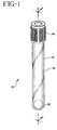
- assembly 20 comprises a tube 30 , a closure 50 , a flexible liner 70 and a seal body 90 .
- Tube 30 has an open end 32 , a closed end 34 and a sidewall 36 extending between the open end and the closed end.
- Sidewall 36 has an outer surface 38 and an inner surface 40.
- Tube 30 defines a receptacle with a central axis "A".
- Tube 30 is preferably made from a substantially transparent and rigid material. Suitable materials for the tube include glass, polystyrene, polyethyleneterephthalate, polycarbonate and the like.
- Closure 50 is disposed to fit over open end 32 of tube 30.
- Closure 50 comprises an annular upper portion 52 that includes a top surface area 56, and a sidewall 58 that converges from surface area 56 towards an upper well area 60 .
- Well area 60 is most preferably a thin diaphragm or a self sealing septum for directing and receiving the point of a needle to be inserted into and through the stopper.
- Well area 60 defines a thin diaphragm or self-sealing septum through which a needle may be inserted.
- the self sealing septum material allows penetration by a piercing element such as a needle and then reseals when the piercing element is withdrawn.
- the closure may be made of natural rubber elastomer, synthetic thermoplastic and thermoset elastomeric materials.
- the closure is made of a resilient elastomeric material whereby the septum is self-sealing.
- flexible liner 70 has an open end 72 that includes a top portion 73 that is secured to the inner surface of tube 30 .
- Liner 70 further includes a closed end 74 and a sidewall 76 extending between the open end and the closed end.
- Sidewall 76 has an outer surface 78 and an inner surface 80 . More particularly, outer surface 78 of top portion 73 is secured to inner surface 40 of tube 30 .
- An interference fit, an adhesive or the like may be used to secure them together.
- Liner 70 may be made from hydrophilic polyurethane, ethylene-octene copolymer, ethylene-butene copolymer and the like.
- Seal body 90 may be of any particular geometric configuration. For purposes of illustration, seal body 90 as shown in FIGS. 1 and 2 as a round body. It is within the purview of the invention that seal body 90 may be hollow, solid or some combination thereof provided that the density of seal body 90 is appropriate to separate higher and lower density fluid components.
- seal body 90 is initially nested in closed end 74 of liner 70 . Seal body 90 is held securely by the liner in its undeformed state. As shown in FIGS. 2 and 3, seal body 90 and the inner wall of the liner form an interference fit.
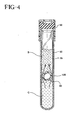
- a fluid sample A is delivered to the tube by a needle that penetrates closure 50 in upper well area 60 .
- the fluid sample is blood.
- a path 100 opens between the liner and the seal body, permitting the flow of the low density component of the fluid past the seal body as the seal body migrates up the liner.
- the high-density component will migrate downwardly past the seal body toward the closed end of the liner.
- seal body 90 serves as a divider between lower specific gravity portion B and higher specific gravity portion C of the fluid sample.
- Liner 70 is compatible with most of the numerous additives used in sample collection tubes such as citrates, silicates, EDTA and the like that are used to condition a fluid sample either to facilitate or retard clotting, or to preserve the fluid sample for a particular analysis. It is within the purview of this invention that one or more additives may be used in the present invention for particular applications.
Applications Claiming Priority (2)
| Application Number | Priority Date | Filing Date | Title |
|---|---|---|---|
| US11092698P | 1998-12-05 | 1998-12-05 | |
| US110926P | 1998-12-05 |
Publications (3)
| Publication Number | Publication Date |
|---|---|
| EP1005909A2 EP1005909A2 (en) | 2000-06-07 |
| EP1005909A3 EP1005909A3 (en) | 2002-06-12 |
| EP1005909B1 true EP1005909B1 (en) | 2004-05-12 |
Family
ID=22335689
Family Applications (1)
| Application Number | Title | Priority Date | Filing Date |
|---|---|---|---|
| EP99124313A Expired - Lifetime EP1005909B1 (en) | 1998-12-05 | 1999-12-06 | Centrifuge tube with round separation element, liner and cap |
Country Status (4)
| Country | Link |
|---|---|
| US (1) | US6497325B1 (ja) |
| EP (1) | EP1005909B1 (ja) |
| JP (1) | JP4188525B2 (ja) |
| DE (1) | DE69917190T2 (ja) |
Cited By (11)
| Publication number | Priority date | Publication date | Assignee | Title |
|---|---|---|---|---|
| US8394342B2 (en) | 2008-07-21 | 2013-03-12 | Becton, Dickinson And Company | Density phase separation device |
| US8563264B2 (en) | 2007-11-20 | 2013-10-22 | 3M Innovative Properties Company | Sample preparation for environmental sampling |
| US8569072B2 (en) | 2007-11-20 | 2013-10-29 | 3M Innovative Properties Company | Sample preparation container and method |
| US8685746B2 (en) | 2007-11-20 | 2014-04-01 | 3M Innovative Properties Company | Sample preparation container and method |
| US8747781B2 (en) | 2008-07-21 | 2014-06-10 | Becton, Dickinson And Company | Density phase separation device |
| US8794452B2 (en) | 2009-05-15 | 2014-08-05 | Becton, Dickinson And Company | Density phase separation device |
| US8991239B2 (en) | 2006-05-22 | 2015-03-31 | 3M Innovative Properties Company | System and method for preparing samples |
| WO2015070273A1 (de) | 2013-11-14 | 2015-05-21 | Greiner Bio-One Gmbh | Aufnahmevorrichtung, verfahren zum bereitstellen derselben sowie verfahren zum trennen eines gemisches |
| US9283704B2 (en) | 2001-06-18 | 2016-03-15 | Becton, Dickinson And Company | Multilayer containers |
| US9333445B2 (en) | 2008-07-21 | 2016-05-10 | Becton, Dickinson And Company | Density phase separation device |
| US9694359B2 (en) | 2014-11-13 | 2017-07-04 | Becton, Dickinson And Company | Mechanical separator for a biological fluid |
Families Citing this family (28)
| Publication number | Priority date | Publication date | Assignee | Title |
|---|---|---|---|---|
| US7947236B2 (en) | 1999-12-03 | 2011-05-24 | Becton, Dickinson And Company | Device for separating components of a fluid sample |
| US6458067B1 (en) * | 2000-06-30 | 2002-10-01 | Beckman Coulter, Inc. | Removable conformal liners for centrifuge containers |
| JP2005098704A (ja) * | 2001-03-13 | 2005-04-14 | Hajime Ogata | 比重の異なる微粒子の分別法 |
| CN1662307A (zh) | 2002-05-13 | 2005-08-31 | 贝克顿·迪金森公司 | 蛋白酶抑制剂样品采集系统 |
| JP2006502415A (ja) | 2002-10-10 | 2006-01-19 | ベクトン・ディキンソン・アンド・カンパニー | カスパーゼ阻害剤を有するサンプル収集システム |
| EP2186567A1 (en) * | 2003-08-05 | 2010-05-19 | Becton, Dickinson and Company | Device and methods for collection of biological fluidsample and treatment of selected components |
| US20050124965A1 (en) * | 2003-12-08 | 2005-06-09 | Becton, Dickinson And Company | Phosphatase inhibitor sample collection system |
| US20070003449A1 (en) * | 2005-06-10 | 2007-01-04 | Mehdi Hatamian | Valve for facilitating and maintaining fluid separation |
| AU2007294555A1 (en) * | 2006-09-08 | 2008-03-13 | Becton, Dickinson And Company | Sample container with physical fill-line indicator |
| WO2008078808A1 (ja) * | 2006-12-27 | 2008-07-03 | Medibic | 真空採血管 |
| EP2217378B1 (en) | 2007-11-20 | 2013-02-13 | 3M Innovative Properties Company | Sample preparation container and method |
| ES2803431T3 (es) | 2008-03-05 | 2021-01-26 | Becton Dickinson Co | Conjunto de contenedor de recogida de acción capilar |
| US20100093551A1 (en) * | 2008-10-09 | 2010-04-15 | Decision Biomarkers, Inc. | Liquid Transfer and Filter System |
| US8309343B2 (en) | 2008-12-01 | 2012-11-13 | Baxter International Inc. | Apparatus and method for processing biological material |
| US8177072B2 (en) * | 2008-12-04 | 2012-05-15 | Thermogenesis Corp. | Apparatus and method for separating and isolating components of a biological fluid |
| WO2011091013A1 (en) | 2010-01-19 | 2011-07-28 | Becton, Dickinson And Company | Container assembly and system for detection thereof |
| US20110178424A1 (en) * | 2010-01-19 | 2011-07-21 | Becton, Dickinson And Company | Specimen Collection Container Having a Transitional Fill-Volume Indicator Indicating Extraction Method |
| DE102010045798A1 (de) * | 2010-09-20 | 2012-04-19 | Universitätsklinikum Hamburg-Eppendorf | Blutentnahmevorrichtung |
| US20120223027A1 (en) * | 2011-03-02 | 2012-09-06 | Jonathan Lundt | Tube and float systems |
| MX347230B (es) | 2011-03-04 | 2017-04-20 | Becton Dickinson Co | Dispositivo para extracción de sangre que contiene inhibidor de lisofosfolipasa. |
| JP2012239441A (ja) * | 2011-05-23 | 2012-12-10 | Seiko Epson Corp | 反応容器 |
| US8950617B2 (en) * | 2012-07-12 | 2015-02-10 | Universiti Putra Malaysia | Non-penetrative blood container and apparatus for vacuuming the same |
| US9427707B2 (en) | 2012-08-10 | 2016-08-30 | Jean I. Montagu | Filtering blood |
| EP3015169B1 (en) | 2014-10-28 | 2024-04-10 | The Regents Of The University Of California | Sample collection tube with curable polymer separator |
| LT3015168T (lt) * | 2014-10-28 | 2017-10-25 | The Regents Of The University Of California | Mišrios sandarinimo medžiagos ir plazmos atskyrimo agentai, skirti kraujo surinkimo vamzdeliams |
| WO2017100798A1 (en) | 2015-12-11 | 2017-06-15 | Siemens Healthcare Diagnostics Inc. | Specimen container and method for separating serum or plasma from whole blood |
| US11478787B2 (en) | 2018-07-09 | 2022-10-25 | Hanuman Pelican, Inc. | Apparatus and methods for separating blood components |
| WO2023049033A1 (en) * | 2021-09-21 | 2023-03-30 | Becton, Dickinson And Company | Dual chamber specimen collection container assembly |
Family Cites Families (22)
| Publication number | Priority date | Publication date | Assignee | Title |
|---|---|---|---|---|
| US3814248A (en) * | 1971-09-07 | 1974-06-04 | Corning Glass Works | Method and apparatus for fluid collection and/or partitioning |
| US3849072A (en) | 1972-04-25 | 1974-11-19 | Becton Dickinson Co | Plasma separator |
| US3897343A (en) * | 1974-02-27 | 1975-07-29 | Becton Dickinson Co | Plasma separator-hydrostatic pressure type |
| US4083788A (en) | 1975-11-19 | 1978-04-11 | Ferrara Louis T | Blood serum-isolation device |
| US4088582A (en) | 1976-01-16 | 1978-05-09 | Sherwood Medical Industries Inc. | Blood phase separation means |
| AT381466B (de) | 1977-03-16 | 1986-10-27 | Ballies Uwe | Trennroehrchen fuer zentrifugaltrennung |
| US4131549A (en) | 1977-05-16 | 1978-12-26 | Ferrara Louis T | Serum separation device |
| US4257886A (en) | 1979-01-18 | 1981-03-24 | Becton, Dickinson And Company | Apparatus for the separation of blood components |
| DE3069996D1 (en) | 1979-03-23 | 1985-03-07 | Terumo Corp | A method for separating blood and a barrier device therefor |
| CA1178257A (en) * | 1980-05-08 | 1984-11-20 | Toshiji Ichikawa | Apparatus for separating blood |
| DE3101733C2 (de) | 1981-01-21 | 1982-10-14 | Uwe Dr.Med. 2300 Kiel Ballies | Trennelement in einem Trennröhrchen zur Zentrifugaltrennung |
| US4443345A (en) | 1982-06-28 | 1984-04-17 | Wells John R | Serum preparator |
| US4818386A (en) | 1987-10-08 | 1989-04-04 | Becton, Dickinson And Company | Device for separating the components of a liquid sample having higher and lower specific gravities |
| US4877520A (en) | 1987-10-08 | 1989-10-31 | Becton, Dickinson And Company | Device for separating the components of a liquid sample having higher and lower specific gravities |
| US5269927A (en) | 1991-05-29 | 1993-12-14 | Sherwood Medical Company | Separation device for use in blood collection tubes |
| JPH06222055A (ja) | 1993-01-22 | 1994-08-12 | Niigata Kako Kk | 液体サンプルの成分分離用分離部材 |
| US5389265A (en) | 1993-06-02 | 1995-02-14 | E. I. Du Pont De Nemours And Company | Phase-separation tube |
| JPH07103969A (ja) | 1993-08-13 | 1995-04-21 | Niigata Kako Kk | 血液分離部材及び血液分離用採血管 |
| US5455009A (en) | 1993-09-14 | 1995-10-03 | Becton, Dickinson And Company | Blood collection assembly including clot-accelerating plastic insert |
| US5575778A (en) | 1994-09-21 | 1996-11-19 | B. Braun Melsungen Ag | Blood-taking device |
| US5632905A (en) | 1995-08-07 | 1997-05-27 | Haynes; John L. | Method and apparatus for separating formed and unformed components |
| AT409725B (de) * | 1997-05-12 | 2002-10-25 | Greiner & Soehne C A | Trennvorrichtung |
-
1999
- 1999-12-03 US US09/454,267 patent/US6497325B1/en not_active Expired - Lifetime
- 1999-12-06 EP EP99124313A patent/EP1005909B1/en not_active Expired - Lifetime
- 1999-12-06 JP JP34695199A patent/JP4188525B2/ja not_active Expired - Lifetime
- 1999-12-06 DE DE69917190T patent/DE69917190T2/de not_active Expired - Fee Related
Cited By (27)
| Publication number | Priority date | Publication date | Assignee | Title |
|---|---|---|---|---|
| US9283704B2 (en) | 2001-06-18 | 2016-03-15 | Becton, Dickinson And Company | Multilayer containers |
| US8991239B2 (en) | 2006-05-22 | 2015-03-31 | 3M Innovative Properties Company | System and method for preparing samples |
| US8563264B2 (en) | 2007-11-20 | 2013-10-22 | 3M Innovative Properties Company | Sample preparation for environmental sampling |
| US8569072B2 (en) | 2007-11-20 | 2013-10-29 | 3M Innovative Properties Company | Sample preparation container and method |
| US8685746B2 (en) | 2007-11-20 | 2014-04-01 | 3M Innovative Properties Company | Sample preparation container and method |
| US9339741B2 (en) | 2008-07-21 | 2016-05-17 | Becton, Dickinson And Company | Density phase separation device |
| US9700886B2 (en) | 2008-07-21 | 2017-07-11 | Becton, Dickinson And Company | Density phase separation device |
| US9933344B2 (en) | 2008-07-21 | 2018-04-03 | Becton, Dickinson And Company | Density phase separation device |
| US9714890B2 (en) | 2008-07-21 | 2017-07-25 | Becton, Dickinson And Company | Density phase separation device |
| US9452427B2 (en) | 2008-07-21 | 2016-09-27 | Becton, Dickinson And Company | Density phase separation device |
| US8747781B2 (en) | 2008-07-21 | 2014-06-10 | Becton, Dickinson And Company | Density phase separation device |
| US9333445B2 (en) | 2008-07-21 | 2016-05-10 | Becton, Dickinson And Company | Density phase separation device |
| US8394342B2 (en) | 2008-07-21 | 2013-03-12 | Becton, Dickinson And Company | Density phase separation device |
| US9802189B2 (en) | 2009-05-15 | 2017-10-31 | Becton, Dickinson And Company | Density phase separation device |
| US9919309B2 (en) | 2009-05-15 | 2018-03-20 | Becton, Dickinson And Company | Density phase separation device |
| US11786895B2 (en) | 2009-05-15 | 2023-10-17 | Becton, Dickinson And Company | Density phase separation device |
| US8794452B2 (en) | 2009-05-15 | 2014-08-05 | Becton, Dickinson And Company | Density phase separation device |
| US11351535B2 (en) | 2009-05-15 | 2022-06-07 | Becton, Dickinson And Company | Density phase separation device |
| US9731290B2 (en) | 2009-05-15 | 2017-08-15 | Becton, Dickinson And Company | Density phase separation device |
| US9079123B2 (en) | 2009-05-15 | 2015-07-14 | Becton, Dickinson And Company | Density phase separation device |
| US9364828B2 (en) | 2009-05-15 | 2016-06-14 | Becton, Dickinson And Company | Density phase separation device |
| US8998000B2 (en) | 2009-05-15 | 2015-04-07 | Becton, Dickinson And Company | Density phase separation device |
| US9919308B2 (en) | 2009-05-15 | 2018-03-20 | Becton, Dickinson And Company | Density phase separation device |
| US9919307B2 (en) | 2009-05-15 | 2018-03-20 | Becton, Dickinson And Company | Density phase separation device |
| US10807088B2 (en) | 2009-05-15 | 2020-10-20 | Becton, Dickinson And Company | Density phase separation device |
| WO2015070273A1 (de) | 2013-11-14 | 2015-05-21 | Greiner Bio-One Gmbh | Aufnahmevorrichtung, verfahren zum bereitstellen derselben sowie verfahren zum trennen eines gemisches |
| US9694359B2 (en) | 2014-11-13 | 2017-07-04 | Becton, Dickinson And Company | Mechanical separator for a biological fluid |
Also Published As
| Publication number | Publication date |
|---|---|
| JP4188525B2 (ja) | 2008-11-26 |
| JP2000237279A (ja) | 2000-09-05 |
| EP1005909A2 (en) | 2000-06-07 |
| EP1005909A3 (en) | 2002-06-12 |
| US6497325B1 (en) | 2002-12-24 |
| DE69917190T2 (de) | 2005-05-04 |
| DE69917190D1 (de) | 2004-06-17 |
Similar Documents
| Publication | Publication Date | Title |
|---|---|---|
| EP1005909B1 (en) | Centrifuge tube with round separation element, liner and cap | |
| EP1014088B1 (en) | Device and method for separating components of a fluid sample | |
| US7153477B2 (en) | Device and method for separating components of a fluid sample | |
| US6516953B1 (en) | Device for separating components of a fluid sample | |
| US6479298B1 (en) | Device and method for separating components of a fluid sample | |
| US6280400B1 (en) | Device and method for separating component of a liquid sample | |
| JP5385383B2 (ja) | 密度相分離装置 | |
| US6471069B2 (en) | Device for separating components of a fluid sample | |
| US6793892B1 (en) | Device and method for separating components of a fluid sample | |
| US6409528B1 (en) | Device and method for collecting, preparation and stabilizing a sample | |
| US6537503B1 (en) | Device and method for separating components of a fluid sample | |
| US8747781B2 (en) | Density phase separation device | |
| US6465256B1 (en) | Device and method for separating components of a fluid sample | |
| US20020132367A1 (en) | Device and method for separating components of a fluid sample |
Legal Events
| Date | Code | Title | Description |
|---|---|---|---|
| PUAI | Public reference made under article 153(3) epc to a published international application that has entered the european phase |
Free format text: ORIGINAL CODE: 0009012 |
|
| AK | Designated contracting states |
Kind code of ref document: A2 Designated state(s): AT BE CH CY DE DK ES FI FR GB GR IE IT LI LU MC NL PT SE |
|
| AX | Request for extension of the european patent |
Free format text: AL;LT;LV;MK;RO;SI |
|
| RIN1 | Information on inventor provided before grant (corrected) |
Inventor name: LIN, FU-CHUNG Inventor name: KARG, JEFFREY Inventor name: DICESARE, PAUL C. |
|
| PUAL | Search report despatched |
Free format text: ORIGINAL CODE: 0009013 |
|
| RIC1 | Information provided on ipc code assigned before grant |
Free format text: 7B 01L 3/14 A, 7G 01N 33/49 B |
|
| AK | Designated contracting states |
Kind code of ref document: A3 Designated state(s): AT BE CH CY DE DK ES FI FR GB GR IE IT LI LU MC NL PT SE |
|
| AX | Request for extension of the european patent |
Free format text: AL;LT;LV;MK;RO;SI |
|
| 17P | Request for examination filed |
Effective date: 20020713 |
|
| 17Q | First examination report despatched |
Effective date: 20020917 |
|
| AKX | Designation fees paid |
Designated state(s): DE FR GB IT |
|
| GRAP | Despatch of communication of intention to grant a patent |
Free format text: ORIGINAL CODE: EPIDOSNIGR1 |
|
| GRAA | (expected) grant |
Free format text: ORIGINAL CODE: 0009210 |
|
| GRAS | Grant fee paid |
Free format text: ORIGINAL CODE: EPIDOSNIGR3 |
|
| AK | Designated contracting states |
Kind code of ref document: B1 Designated state(s): DE FR GB IT |
|
| REG | Reference to a national code |
Ref country code: GB Ref legal event code: FG4D |
|
| REG | Reference to a national code |
Ref country code: IE Ref legal event code: FG4D |
|
| REF | Corresponds to: |
Ref document number: 69917190 Country of ref document: DE Date of ref document: 20040617 Kind code of ref document: P |
|
| ET | Fr: translation filed | ||
| PGFP | Annual fee paid to national office [announced via postgrant information from national office to epo] |
Ref country code: DE Payment date: 20050131 Year of fee payment: 6 |
|
| PLBE | No opposition filed within time limit |
Free format text: ORIGINAL CODE: 0009261 |
|
| STAA | Information on the status of an ep patent application or granted ep patent |
Free format text: STATUS: NO OPPOSITION FILED WITHIN TIME LIMIT |
|
| 26N | No opposition filed |
Effective date: 20050215 |
|
| PG25 | Lapsed in a contracting state [announced via postgrant information from national office to epo] |
Ref country code: IT Free format text: LAPSE BECAUSE OF NON-PAYMENT OF DUE FEES;WARNING: LAPSES OF ITALIAN PATENTS WITH EFFECTIVE DATE BEFORE 2007 MAY HAVE OCCURRED AT ANY TIME BEFORE 2007. THE CORRECT EFFECTIVE DATE MAY BE DIFFERENT FROM THE ONE RECORDED. Effective date: 20051206 |
|
| PG25 | Lapsed in a contracting state [announced via postgrant information from national office to epo] |
Ref country code: DE Free format text: LAPSE BECAUSE OF NON-PAYMENT OF DUE FEES Effective date: 20060701 |
|
| REG | Reference to a national code |
Ref country code: FR Ref legal event code: PLFP Year of fee payment: 17 |
|
| REG | Reference to a national code |
Ref country code: FR Ref legal event code: PLFP Year of fee payment: 18 |
|
| REG | Reference to a national code |
Ref country code: FR Ref legal event code: PLFP Year of fee payment: 19 |
|
| PGFP | Annual fee paid to national office [announced via postgrant information from national office to epo] |
Ref country code: GB Payment date: 20181127 Year of fee payment: 20 Ref country code: FR Payment date: 20181127 Year of fee payment: 20 |
|
| REG | Reference to a national code |
Ref country code: GB Ref legal event code: PE20 Expiry date: 20191205 |
|
| PG25 | Lapsed in a contracting state [announced via postgrant information from national office to epo] |
Ref country code: GB Free format text: LAPSE BECAUSE OF EXPIRATION OF PROTECTION Effective date: 20191205 |