EP1005426B1 - Application of substances on a package - Google Patents
Application of substances on a package Download PDFInfo
- Publication number
- EP1005426B1 EP1005426B1 EP98942159A EP98942159A EP1005426B1 EP 1005426 B1 EP1005426 B1 EP 1005426B1 EP 98942159 A EP98942159 A EP 98942159A EP 98942159 A EP98942159 A EP 98942159A EP 1005426 B1 EP1005426 B1 EP 1005426B1
- Authority
- EP
- European Patent Office
- Prior art keywords
- surface area
- selected surface
- container
- application means
- ink jet
- Prior art date
- Legal status (The legal status is an assumption and is not a legal conclusion. Google has not performed a legal analysis and makes no representation as to the accuracy of the status listed.)
- Expired - Lifetime
Links
Images

Classifications
-
- B—PERFORMING OPERATIONS; TRANSPORTING
- B65—CONVEYING; PACKING; STORING; HANDLING THIN OR FILAMENTARY MATERIAL
- B65B—MACHINES, APPARATUS OR DEVICES FOR, OR METHODS OF, PACKAGING ARTICLES OR MATERIALS; UNPACKING
- B65B61/00—Auxiliary devices, not otherwise provided for, for operating on sheets, blanks, webs, binding material, containers or packages
- B65B61/26—Auxiliary devices, not otherwise provided for, for operating on sheets, blanks, webs, binding material, containers or packages for marking or coding completed packages
-
- B—PERFORMING OPERATIONS; TRANSPORTING
- B41—PRINTING; LINING MACHINES; TYPEWRITERS; STAMPS
- B41J—TYPEWRITERS; SELECTIVE PRINTING MECHANISMS, i.e. MECHANISMS PRINTING OTHERWISE THAN FROM A FORME; CORRECTION OF TYPOGRAPHICAL ERRORS
- B41J2/00—Typewriters or selective printing mechanisms characterised by the printing or marking process for which they are designed
- B41J2/005—Typewriters or selective printing mechanisms characterised by the printing or marking process for which they are designed characterised by bringing liquid or particles selectively into contact with a printing material
- B41J2/01—Ink jet
-
- B—PERFORMING OPERATIONS; TRANSPORTING
- B41—PRINTING; LINING MACHINES; TYPEWRITERS; STAMPS
- B41J—TYPEWRITERS; SELECTIVE PRINTING MECHANISMS, i.e. MECHANISMS PRINTING OTHERWISE THAN FROM A FORME; CORRECTION OF TYPOGRAPHICAL ERRORS
- B41J3/00—Typewriters or selective printing or marking mechanisms characterised by the purpose for which they are constructed
- B41J3/407—Typewriters or selective printing or marking mechanisms characterised by the purpose for which they are constructed for marking on special material
- B41J3/4073—Printing on three-dimensional objects not being in sheet or web form, e.g. spherical or cubic objects
- B41J3/40733—Printing on cylindrical or rotationally symmetrical objects, e. g. on bottles
Definitions
- the invention relates to a process for producing packaging systems comprising a hollow body in line.
- a first kind of printing technique used in the industry consists in printing a large number of labels which are being stored onto large reels, such reels being thereafter fed onto a production line to be glued onto bottles, for example.
- a second kind of printing techniques consists in applying ink directly onto the outer surface of a bottle, whereby the print itself can be customised so as to indicate for example the date of production or a particular reference number.
- the present invention concerns a process for producing a packaging system comprising a first step and a second step, the packaging system comprising a hollow body, the first step consisting in applying a first substance onto a selected surface area of the packaging system by use of first application means, the selected surface area and the hollow body being both in motion relative to the first application means and the selected surface area being solely in contact with the first substance during the first step.
- a process is known from the second printing technique mentioned above, whereby a custom print is applied directly onto a bottle, the letters or numbers of the print being typically formed from a number of black dots.
- custom printing information directly onto a bottle while in motion relative to the application means is that such information can be different for each bottle produced, and that such printing can occur at high speed on line.
- Such a process is particularly useful for example in the food or pharmaceutical industry, whereby it is preferable that a package carries an identification number or a production date, for example.
- custom printing differs from the other existing process of the first kind above, whereby labels are pre-printed independently in a separate process and stored onto reels, prior to being glued in line onto a bottle. Indeed, in such a process using reels of printed labels, all labels will be identical, and any label will correspond on the line to any bottle.
- such a process using reels of printed labels allows use of labels having relatively high definition graphics, instead of using a limited number of mono-colour dots to reconstitute letters or numbers.
- a further disadvantage with the use of labels is that if the decoration artwork changes, any remaining labels must be thrown away, and new labels printed. From the time the new artwork is approved, it typically takes 4 to 6 weeks to make new printing cylinders or plates, and print and deliver the labels, ready for application.
- Thermal transfer printing techniques have also been used to form images directly onto containers. However, such techniques also tend to be slow and, again, tend to result in poor image quality. In addition, pressure and/or heat applied to the container being printed by the transfer mechanism may result in damage to the container, which is clearly undesirable. Furthermore, the transfer process requires the use of a transfer film which adds unnecessary waste and cost.
- Ink jet printing has typically been used to print paper or other absorbent materials with water or oil-based inks. While the application of ink jet methodology for use on containers of both circular and non-circular cross-section is described in the prior art, as yet a process has not been developed having a speed suitable for present day commercial production.
- Canadian Patent No. 1277176 discloses a process and apparatus employing ink jet methodology for decorating a container of generally round cross-section, for example circular or oval.
- the process relies upon relative motion of the container to be printed and an ink jet printing head, and builds up the total image in a step-wise fashion. It achieves this either by rotating the container about its longitudinal axis and simultaneously moving it in the direction of that axis while maintaining the ink jet head stationary, or by simply rotating the container and moving the ink jet head step-wise along the longitudinal axis of the container. Formation of the final image is, therefore, slow.
- the process is generally unsuitable for the printing of large numbers of containers in a continuous manner meeting present day speed requirements.
- a similar technique is also disclosed in GB-2 107 414 A.
- the apparatus includes a relatively complex handling mechanism for the container comprising a carrier for the container which has an endless wall portion having a profile matching the side wall of the container and which is to be passed through the nip between two rollers adjacent an ink jet head, causing the side wall of the container to pass in front of that head with a constant distance therebetween.
- This process and apparatus is only suitable for printing tub-like containers, or containers having an opening at least the size of their base, and is not suitable for the printing of bottles. Also, printing of a number of containers can only be achieved in a start-stop manner, rather than continuously, as each container must make a full revolution in front of the printing head before moving onwards, and allowing another container to move into a printing position. Consequently, the printing process is slow, typically less than 100 containers per minute, and is inadequate for present day commercial printing of, for example, bottles, which is typically required to be 150 to 500 containers per minute.
- the invention seeks to provide a process for producing a packaging system of the above mentioned kind which can provide both flexibility and high resolution in the application of a substance to a packaging system, and which can operate in a wide range of speeds for industrial production.
- this object is accomplished in a process of the above kind in that the second step consists in applying a second substance onto the selected surface area by use of second application means after completion of the first step, the selected surface area and the hollow body being both in motion relative to the second application means and the selected surface area being solely in contact with the second substance during the second step, the process taking place at a continuous line speed.
- a process in accordance with the invention has a number of advantages. Since it comprises the application of a second substance as well as the first substance onto the selected surface area while both the hollow body and the selected surface area are in motion relative to the first or second application means, it allows to obtain both flexibility as the application can be made directly in line, and higher resolution in that more than a single substance is applied onto the selected surface area of the packaging system. Due to the improved flexibility, storage such as for example storage of high definition labels onto reels, is significantly reduced, such lowering production costs. Furthermore, flexibility allows for example to reduce wastage of printed labels which are not used, thus being beneficial to the environment.
- the process of the invention relates to packaging system.
- a packaging system could consist in a container.
- the packaging system could also relate to a container and a label for the container, taken together or separately.
- the packaging system could be processed in the following manner: the selected surface area may be onto the label, the selected surface area situated on the label being treated by the process according to the invention prior to being applied onto the container.
- the container is in motion also according to the invention, even if the label is not applied onto the container yet.
- both the container and the label are on line, the line being such that the label will be applied after printing, for example.
- the label could also be applied blank onto the container and the substances may be applied onto the selected surface area situated on the label as the label is already fixed to the container.
- a label may not be used, so that application of the substance may take place directly onto the container.
- the invention also relates to a body.
- a hollow body is a container, such as the containers used for consumer products.
- Preferred hereby would be containers made from a material comprising thermoplastic resins.
- the first step of the process according of the invention consists in applying a first substance onto a selected surface area.
- the substance is an ink, which is preferably applied using ink-jet technology.
- the selected surface area is onto the packaging system, and preferably covers at least 30 cm 2 . Therefore, it could be placed for example on a label, on a container, on a cap or on a box.
- Application is made using first application means.
- such means comprise an ink-jet head of an ink jet printer, preferably an ink-jet head having a plurality of nozzles.
- the selected surface area and the hollow body are both in motion relative to the first application means. This does not prevent the selected surface area and the hollow body to move separately, as a label may be printed prior to being applied, for example.
- these two components of the packaging system are in motion on the production line.
- the relative movement could comprise a component consisting in a movement of the first application means themselves. Indeed, in particular when printing on a non planar selected surface area, it may be preferable to move the application means as well as the selected surface area itself.
- the hollow body is in motion also, so that, in case of printing on a label prior to application on the hollow body, the hollow body is in motion on the line towards the point where application of the label will take place.
- the selected surface area is onto the surface of a label, the label being fixed onto the rest of the packaging system after application of the substances.
- the selected surface area is an integral part of the outer surface of the hollow body.
- the selected surface area is solely in contact with the first substance during the first step. This means that there is no friction between any elements and the selected surface area. It should be noted that if the selected surface area is placed onto a label, the label itself may be in contact with for example the bottle. Indeed, the selected surface area is meant to be a two dimensional surface. Such a friction on the selected surface area would for example in a screen printing application, the speed of which is not compatible with the process of the invention.
- the second step of the invention is similar to the first step and follows the first step.
- the process according to he invention is taking place at any current line speed depending on the sophistication of the inkjet technology used and the number of heads printing identical colours. This is rendered possible by the continuous movement of the elements of the packaging system and by the absence of friction onto the selected surface area. Further more, the plurality of application means allows also to progress with a greater line speed, while obtaining a satisfactory application.
- the process takes place at a speed of at least 10 meters per minute, more preferably at least 15 meters per minute, even more preferably at least 20 meters per minute and most preferably at least 28 meters per minute.
- the process further comprises one or more extra steps, the extra step consisting in applying an extra substance onto the selected surface area by use of extra application means after completion of the prior step, the selected surface area and the hollow body being both in motion relative to the extra application means and the selected surface area being solely in contact with the extra substance during the extra step.
- the extra step consisting in applying an extra substance onto the selected surface area by use of extra application means after completion of the prior step, the selected surface area and the hollow body being both in motion relative to the extra application means and the selected surface area being solely in contact with the extra substance during the extra step.
- a most preferred embodiment comprises four extra steps, each of the six substances being a different ink, so that high resolution images may be achieved, as well as high resolution grey scale images with a high contrast.
- a process for printing an image onto a selected surface area comprises moving a line of containers in a continuous manner past an ink jet head having an array of nozzles spaced apart in a direction transverse to the direction of movement of the line of containers and through which ink is ejected, and moving each container and/or the ink jet head relative to one another as the said container passes the ink jet head, so that during printing the distance between the ink jet head and the container surface to be printed remains substantially constant and so that each portion of the said surface passes the ink jet head only once.
- an apparatus for printing an image onto container surfaces comprises a receptacle for each container, conveyor means for moving the receptacles in a continuous manner past an ink jet head having an array of nozzles transverse to the direction of movement of the receptacles and through which ink is ejected, and means for moving each container and/or the ink jet head relative to one another as the said container passes the ink jet head, so as to maintain during printing a constant distance between the container surface to be printed and the ink jet head and so that each portion of the said surface passes the ink jet head only once.
- the process and apparatus of the preferred embodiments of the invention are capable of printing, or decorating, non-planar containers at speeds suitable for commercial production.
- the process is capable of printing at least 150 containers per minute, preferably more than 300 containers per minute, and more preferably up to 500 containers per minute, while achieving high image quality and avoiding damage to the containers.
- Another advantage of the present invention is that it is readily adaptable for use with different shapes and/or sizes of containers or labels, for example, and different artwork and/or text.
- Yet another advantage of the present invention is that it is capable of decorating containers at reduced cost compared to prior art processes, by for example eliminating the need for labels and backing papers, transfer films, or printing plates that are expensive to design and maintain. It should be noted that for example, a container having a non-planar surface and having an image printed on that surface is obtainable by a process or by use of apparatus as described above.
- a line of containers is moved continuously past an ink jet head.
- a line of containers it is intended to cover a row of containers, or any other arrangement whereby a number of containers passes an ink jet head in sequence.
- the containers may be positioned vertically or horizontally during printing, but preferably they are positioned vertically.
- the line of containers when the line of containers is described as moving continuously it is intended to mean that between printing one container and the next container in the line, the line of containers does not stop moving, unless, for example, a change in the process needs to be made, or maintenance of the printing apparatus is required.
- the position and size of the ink dots produced on the surface of the container will vary according to which portion of the surface is being printed, which may in some places lead to smudging of the image, and in others a very faint image, or result in damage to the ink jet head or container.
- the distance between the surface to be printed and the ink jet head will be set at a pre-determined value.
- the pre-determined distance will be maintained in the range 0.2 to 4 mm, preferably 0.5 to 2.5 mm, as with larger distances air currents may interfere with the ink jet, leading to poor image quality. This is what is meant by a substantially constant distance in the context of this Application. More preferably, the distance is maintained as constant at 1mm "0.5mm.
- the pre-determined distance is maintained by moving the container to be printed and/or the ink jet head.
- the ink jet head may be made to move to follow the profile of the container to be printed.
- the ink jet head it is preferred, for simplicity, that the ink jet head remain stationary, and that each container is caused to move relative thereto.
- each container prior to printing, each container is arranged so that the leading portion, or edge, of the container surface to be printed, in the direction of movement of the line of containers, is at the pre-determined distance from the ink jet head.
- the container is then, gradually, moved and rotated about its longitudinal axis to bring each portion of the container surface in turn to the pre-determined set distance from the ink jet head as the surface moves past that head, until the trailing portion, or edge, of the container surface is at the pre-determined distance from the ink jet head.
- the speed of the overall process that when rotating each container each portion of its surface that is to be printed passes the ink jet head only once.
- the direction and angle of rotation first applied will depend upon the shape of the container to be printed, and the shape of any curved path it is made to follow. For instance, if the container is made to move in a substantially straight line and has a surface which is convex to the ink jet head, the leading portion of that surface must first be moved towards the ink jet head, and then gradually away from the ink jet head until the ink jet head reaches the apex, or turning point, of the curved surface, and then the trailing edge of the surface must be moved gradually towards the ink jet head.
- the container may have to rotate either towards or away from the ink jet head, depending upon the respective radii of curvature of the curved path and the container surface.
- the radius of the curvature of the container will be less than that of the curved path, and this requires movement as described above.
- the leading edge of the container may first have to be moved gradually away from the ink jet head until the head reaches the apex of the curved surface, and then the trailing edge moved so that this gradually approaches the head.
- the frequency at which ink drops are ejected from the ink jet head may need to be adjusted to compensate for the slight variation in linear velocity of the container surface as it passes the ink jet head.
- the ink jet ejection timing may also need to be adjusted to compensate for the fact that for the mostpart during printing the ink jet head is not normal to the container surface.
- Movement of the container relative to the ink jet head in the required manner may be achieved in a number of ways. For instance, a simple servo motor can be used, or a cam mechanism. If a motor is used it will, typically, be controlled by a computer program specific to the size and shape of the container being printed, so that a simple change of program will adapt the process for printing a different container. This may, therefore, prove more convenient than using a cam mechanism.
- the present invention may utilise at least one sensor to monitor the distance between the container surface and the ink jet head.
- Any suitable sensor can be used, for instance an infra-red sensor, a laser sensor, a sonic proximity sensor.
- the sensor is in communication with the means for moving the ink jet head and/or container relative to one another, allowing adjustment of that moving means if necessary during a print cycle, or after changing over from printing one type of container to another, of a different size and/or shape.
- each container is held within a receptacle on a conveyor or a carrousel.
- movement of each container relative to the ink jet head may be achieved by moving its respective receptacle
- Each receptacle preferably comprises means for holding its container so there is substantially no relative motion between the container and its receptacle during the printing operation.
- the holding means contacts the container at at least one position at its top and its base.
- Any suitable holding means can be used, one example is to employ a tapered stopper, for insertion into the top of the container to a snug fit, and to hold the base of the container in a tapered receptacle having substantially the same profile as the base of the container.
- the nature of the holding means allows the receptacle to be used with containers of different sizes and/or shapes, and to be readily adaptable thereto, thereby allowing conversion from one product line to another, with minimal delay, which represents a significant advantage in present day commercial production.
- the process of the invention may use one or a number of ink jet heads, depending upon the complexity of the image to be printed and/or the number of surfaces of the container to be printed.
- Each ink jet head comprises an array of nozzles that are spaced apart in a direction transverse to the direction of movement of the line, or row, of containers to be printed.
- Ink may be ejected from the nozzles in a continuous manner or on a drop-on-demand basis, under digital control, as is well described in the literature.
- ink is ejected from the nozzles on a drop-on-demand basis.
- each ink jet head will have at least 7 nozzles per mm, preferably at least 12 nozzles per mm, which may be arranged in one or more parallel lines. Most preferably, the ink jet head will be capable of printing at least 200 drops of ink per inch in the direction of the longitudinal axis of the container passing, and preferably 360 drops per inch.
- XaarJet 1000 or XaarJet 1000S supplied by Xaar.
- the accuracy of registration that is required is such that the error in positioning of differently-coloured dots is 100-400 microns, preferably less than 200 microns, and more preferably less than or equal to 70 microns.
- the process of the invention may be combined with special colour printing techniques.
- special colour printing techniques For instance, to achieve maximum flexibility and high quality printing, it is preferred to use so called “Hi-Fi” colour printing using 6 to 7 colours. This may utilize for example cyan, magenta, yellow and black, plus either i) green and orange or ii) red, green and blue. This expands the colour space available and enables higher quality decoration at relatively low cost, and avoids the need for numerous special colours in order to produce solid colours, as is typical in printing artwork for containers.
- each container When it is desired to print more than one portion of a container surface, for instance diametrically-opposed surface portions or opposite sides of a container, after each container has passed a first ink jet head it is rotated about its longitudinal axis, for example through at least 90°, to present the next surface portion or side of the container to be printed to another ink jet head. For instance, if opposite sides of a container are to be printed, each container will simply be rotated through approximately 180° between the ink jet heads or sets of ink jet heads. Then, when printing the second surface portion or side, the container and/or the ink jet head is again caused to move in the manner described above, in order to maintain a substantially constant distance between the container surface and the ink jet head.
- any suitable ink may be used for printing, although certain inks may be preferred depending upon the material from which the container to be printed is made.
- a phase-change ink such as a hot-melt ink, a heat-fusable non-solvent toner ink, or a radiation-curable ink, typically a UV-curable ink.
- a means for fusing or curing the ink is preferably provided, either after each ink jet head, if there are a number of these, and/or at the end of the overall printing process.
- the container surface should have sufficiently high surface energy to enable ink adhesion. This can be accomplished, for example, by flame treatment of plastic containers, as is well known in the art.
- the radiation curable inks may be preferred over those that require drying by heating, as their use is less likely to result in damage to the container. UV-curable inks are particularly preferred, as these adhere readily to plastic surfaces and are durable. The use of such inks in ink jet technology is described in the art.
- the present invention is suitable for printing a wide variety of sizes and/or shapes of container, but is particularly suited to printing containers having curved or non-planar surfaces. It is particularly suitable for printing containers having surfaces which curve in one sense or direction only, for instance surfaces which are either convex or concave, as opposed to surfaces containing both convex and concave portions. Examples include bottles which are circular or oval in cross-section.
- the present invention is also suitable for printing containers of a wide variety of materials, for instance paper-board, cardboard, plastic, glass, and metal. Its principle purpose, however, is for printing relatively lightweight plastic containers, typically of polyethylene polypropylene, nylon, polyester, or polyvinylalcohol, for use in the detergent, beauty-care, cosmetics and food industries, as well as labels, for example. As products in these industries often require updating on a regular basis, and quickly in response to market change or competitor activity, it is essential that containers be printed quickly, and that the printing process can be adapted readily to different product lines.
- the present invention satisfies both these requirements for the first time, and at high speeds similar to filling-line speeds.
- apparatus 1 comprises a rotating carrousel 2 which carries a number of receptacles 3 which carry bottles 4 past a series of ink jet heads 5.
- Each receptacle comprises holding means (not shown) for its respective bottle.
- Each of the receptacles is movable on the carrousel so as to maintain a small and substantially constant distance between the surface of the bottle to be printed and the respective ink jet head.
- a UV lamp 6 is provided after each ink jet head, in order to cure the ink printed onto the bottle, and a further UV lamp 7 is provided, if needed, after the final ink jet head, to ensure complete curing of the printed inks.
- optical fibres may be employed to convey UV light from a more distant source, thereby conserving space.
- the individual bottles 4 are deposited in their respective receptacles 3 by a conveyor 8 leading from a sorter 9 of conventional type. While on conveyor 8, the bottles may be subject to other treatments, for instance by a flame treater 10, which acts to reduce surface tension and promote ink adhesion.
- a 180°-rotation station 11 is provided, to present the other side of the container, which has already been printed, to the subsequent ink jet heads.
- the bottles After printing, the bottles leave the carrousel and are subject to inspection as to print quality using video equipment 12.
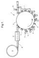
- a bottle 21 is held in a tapered puck 22, with a tapered plug 23, suspended from a frame 24, inserted into the top of the bottle.
- the puck is supported on a carousel 25 (only a portion of which is shown) which causes the bottle to pass ink jet head 26.
- motor 27 rotates shaft 28 which is attached to the puck, thereby rotating the bottle in front of the ink jet head.
- the motor is programmable to cause rotation of the bottle so that the distance between the bottle surface to be printed and the ink jet head is maintained, typically, below 2 mm.
Landscapes
- Engineering & Computer Science (AREA)
- Manufacturing & Machinery (AREA)
- Mechanical Engineering (AREA)
- Ink Jet (AREA)
- Medicinal Preparation (AREA)
- Auxiliary Devices For And Details Of Packaging Control (AREA)
- Printing Methods (AREA)
- Supplying Of Containers To The Packaging Station (AREA)
- Coating Apparatus (AREA)
- Electrical Discharge Machining, Electrochemical Machining, And Combined Machining (AREA)
- Wrappers (AREA)
- Details Of Rigid Or Semi-Rigid Containers (AREA)
Abstract
Description
It should be noted that for example, a container having a non-planar surface and having an image printed on that surface is obtainable by a process or by use of apparatus as described above.
Claims (10)
- A process for producing a packaging system comprising a first step and a second step, whereinthe process being characterised in that(a) the packaging system (4) comprises a hollow body,(b) the first step consists in applying a first substance onto a selected surface area of the packaging system by use of first application means, the selected surface area being in motion relative to the first application means (5) and the selected surface area being in contact with the first substance, but not in contact with the first application means during the first step,(c) the second step consists in applying a second substance onto the selected surface area by use of second application means (5) after completion of the first step, the selected surface area being in motion relative to the second applications means and the selected surface area being in contact with the second substance, but not in contact with the second application means during the second step,
during said first step, the hollow body is in motion relative to said first application means, and there is no friction between the selected surface and the first application means,
during said second step, the hollow body is in motion relative to said second application means, and there is no friction between the selected surface and second application means, and
the process takes place at a continuous line speed. - A process as in claim 1, whereby the process further comprises one or more extra steps, wherein the extra step consists in applying an extra substance onto the selected surface area by use of extra application means (5) after completion of the prior step, the selected surface area and the hollow body being both in motion relative to the extra application means and the selected surface area being in contact with the extra substance, but not in contact with the extra application means during the extra step.
- A process as in claim 2, whereby four extra steps are following the second step, so that application of six substances occurs.
- A process as in claim 1, whereby the first and second substances are inks.
- A process as in claim 1, whereby the hollow body is a bottle (4) or a cap made from a material comprising thermoplastic resins.
- A process as in claim 1, whereby the selected surface area is the surface of a label, the label being fixed onto the rest of the packaging system after application of the substances.
- A process as in claim 1, whereby the selected surface area is an integral part of the outer surface of the hollow body.
- A process as in claim 1, whereby the selected surface area covers at least 30 cm2.
- A process as in claim 1, whereby the application means are ink jet printers.
- A process as in claim 1, whereby the selected surface area is non-planar.
Applications Claiming Priority (3)
| Application Number | Priority Date | Filing Date | Title |
|---|---|---|---|
| GBGB9717776.0A GB9717776D0 (en) | 1997-08-21 | 1997-08-21 | Printing process and apparatus |
| GB9717776 | 1997-08-21 | ||
| PCT/US1998/017260 WO1999008935A1 (en) | 1997-08-21 | 1998-08-20 | Application of substances on a package |
Publications (2)
| Publication Number | Publication Date |
|---|---|
| EP1005426A1 EP1005426A1 (en) | 2000-06-07 |
| EP1005426B1 true EP1005426B1 (en) | 2003-02-26 |
Family
ID=10817857
Family Applications (1)
| Application Number | Title | Priority Date | Filing Date |
|---|---|---|---|
| EP98942159A Expired - Lifetime EP1005426B1 (en) | 1997-08-21 | 1998-08-20 | Application of substances on a package |
Country Status (13)
| Country | Link |
|---|---|
| EP (1) | EP1005426B1 (en) |
| JP (1) | JP2004500280A (en) |
| KR (1) | KR20010023135A (en) |
| CN (1) | CN1144732C (en) |
| AT (1) | ATE233201T1 (en) |
| AU (1) | AU9027498A (en) |
| BR (1) | BR9811333A (en) |
| CA (1) | CA2301917A1 (en) |
| DE (1) | DE69811683T2 (en) |
| ES (1) | ES2191327T3 (en) |
| GB (1) | GB9717776D0 (en) |
| IL (1) | IL134617A0 (en) |
| WO (1) | WO1999008935A1 (en) |
Families Citing this family (29)
| Publication number | Priority date | Publication date | Assignee | Title |
|---|---|---|---|---|
| DE10004022A1 (en) * | 2000-01-31 | 2001-08-02 | Focke & Co | Method and device for applying codes to (cigarette) packs |
| DE10029181A1 (en) * | 2000-06-14 | 2001-12-20 | Balsfulland Maschfabrik Gmbh | Device for decorating individual objects |
| US6769357B1 (en) | 2003-06-05 | 2004-08-03 | Sequa Can Machinery, Inc. | Digital can decorating apparatus |
| US7210408B2 (en) | 2004-12-30 | 2007-05-01 | Plastipak Packaging, Inc. | Printing plastic containers with digital images |
| DE102006001223A1 (en) | 2006-01-10 | 2007-07-12 | Khs Ag | Apparatus for printing on bottles or similar containers |
| DE102006001204C5 (en) * | 2006-01-10 | 2015-06-18 | Khs Gmbh | Method for labeling bottles or similar containers and labeling machine for carrying out the method |
| US7625059B2 (en) * | 2006-11-22 | 2009-12-01 | Plastipak Packaging, Inc. | Digital printing plastic containers |
| US9272815B2 (en) | 2006-05-09 | 2016-03-01 | Plastipak Packaging, Inc. | Digital printing plastic container |
| US8522989B2 (en) | 2006-05-09 | 2013-09-03 | Plastipak Packaging, Inc. | Plastic containers with a base coat thereon |
| DE102008012502B4 (en) * | 2008-03-04 | 2021-05-12 | Krones Aktiengesellschaft | Device for the continuous printing of containers with a curved printing surface |
| DE102008023939A1 (en) | 2008-05-16 | 2009-11-19 | Krones Ag | Device for labeling containers with printing unit |
| CA2728127C (en) | 2008-06-24 | 2014-01-28 | Plastipak Packaging, Inc. | Apparatus and method for printing on articles having a non-planar surface |
| CA2738808A1 (en) * | 2008-10-20 | 2010-04-29 | Plastipak Packaging, Inc. | Digital printing plastic containers with improved adhesion and recyclability |
| US10400118B2 (en) | 2008-10-20 | 2019-09-03 | Plastipak Packaging, Inc. | Methods and compositions for direct print having improved recyclability |
| DE102009013477B4 (en) * | 2009-03-19 | 2012-01-12 | Khs Gmbh | Printing device for printing on bottles or similar containers |
| DE102009033810A1 (en) | 2009-07-18 | 2011-01-27 | Till, Volker, Dipl.-Ing. | Plant for printing on containers |
| IT1395434B1 (en) * | 2009-07-24 | 2012-09-14 | Sacmi Labelling S P A Ora Sacmi Verona S P A | EQUIPMENT FOR LABELING OF CONTAINERS BY SLEEVE LABELS |
| CA2805674A1 (en) * | 2010-07-23 | 2012-01-26 | Plastipak Packaging, Inc. | Rotary system and method for printing containers |
| DE102011009391A1 (en) | 2011-01-25 | 2012-07-26 | Krones Aktiengesellschaft | Apparatus and method for printing on containers |
| DE102011113150A1 (en) | 2011-09-14 | 2013-03-14 | Khs Gmbh | Method and device for treating packaging by applying equipment |
| JP6242803B2 (en) * | 2012-11-06 | 2017-12-06 | 日本クロージャー株式会社 | Inkjet printing method for molded products |
| DE102013217674A1 (en) * | 2013-09-04 | 2015-03-05 | Krones Ag | Device for aligning components of a rotary machine |
| JP6492433B2 (en) * | 2014-07-11 | 2019-04-03 | セイコーエプソン株式会社 | Recording apparatus and recording method |
| CN107107638A (en) * | 2014-11-13 | 2017-08-29 | 宝洁公司 | The product of digital printing |
| CN104441985B (en) * | 2014-12-15 | 2016-03-02 | 北京美科艺数码科技发展有限公司 | Inkjet-printing device, inkjet printing methods and print object cylindricity detection method |
| JP6714893B2 (en) * | 2015-01-06 | 2020-07-01 | 大日本印刷株式会社 | Plastic bottle and method for manufacturing the same |
| CN109572207B (en) * | 2018-10-31 | 2020-08-04 | 重庆宏劲印务有限责任公司 | Device and method for printing three-dimensional pattern on bottle body in gloss oil spraying mode |
| US11491803B2 (en) | 2019-02-12 | 2022-11-08 | The Procter & Gamble Company | Method and apparatus for applying a material onto articles using a transfer component |
| US11752792B2 (en) | 2020-03-09 | 2023-09-12 | The Procter & Gamble Company | Method and apparatus for applying a material onto articles using a transfer component |
Family Cites Families (5)
| Publication number | Priority date | Publication date | Assignee | Title |
|---|---|---|---|---|
| US3730133A (en) * | 1970-03-05 | 1973-05-01 | American Cyanamid Co | Apparatus for remote marking of articles of manufacture |
| AU1175183A (en) * | 1982-03-08 | 1983-09-15 | Kiwi Coders Corp. | Variable size ink printing |
| DE3302616A1 (en) * | 1983-01-27 | 1984-08-02 | Cyklop International Emil Hoffmann KG, 5000 Köln | DEVICE FOR SIGNING OBJECTS |
| DE3526769A1 (en) * | 1985-07-26 | 1987-01-29 | Schmalbach Lubeca | METHOD FOR DECORATING METAL OR PLASTIC CONTAINERS |
| GB2230233A (en) * | 1989-03-02 | 1990-10-17 | Mb Group Plc | An apparatus for, and method of printing on an article having an endless surface |
-
1997
- 1997-08-21 GB GBGB9717776.0A patent/GB9717776D0/en not_active Ceased
-
1998
- 1998-08-20 JP JP2000509636A patent/JP2004500280A/en not_active Withdrawn
- 1998-08-20 CA CA002301917A patent/CA2301917A1/en not_active Abandoned
- 1998-08-20 BR BR9811333-0A patent/BR9811333A/en active Search and Examination
- 1998-08-20 ES ES98942159T patent/ES2191327T3/en not_active Expired - Lifetime
- 1998-08-20 WO PCT/US1998/017260 patent/WO1999008935A1/en active IP Right Grant
- 1998-08-20 EP EP98942159A patent/EP1005426B1/en not_active Expired - Lifetime
- 1998-08-20 DE DE69811683T patent/DE69811683T2/en not_active Expired - Fee Related
- 1998-08-20 KR KR1020007001758A patent/KR20010023135A/en not_active Application Discontinuation
- 1998-08-20 AT AT98942159T patent/ATE233201T1/en not_active IP Right Cessation
- 1998-08-20 CN CNB988094819A patent/CN1144732C/en not_active Expired - Fee Related
- 1998-08-20 AU AU90274/98A patent/AU9027498A/en not_active Abandoned
- 1998-08-20 IL IL13461798A patent/IL134617A0/en unknown
Also Published As
| Publication number | Publication date |
|---|---|
| CN1271319A (en) | 2000-10-25 |
| CA2301917A1 (en) | 1999-02-25 |
| GB9717776D0 (en) | 1997-10-29 |
| ATE233201T1 (en) | 2003-03-15 |
| DE69811683T2 (en) | 2003-12-04 |
| BR9811333A (en) | 2000-09-19 |
| EP1005426A1 (en) | 2000-06-07 |
| WO1999008935A1 (en) | 1999-02-25 |
| DE69811683D1 (en) | 2003-04-03 |
| CN1144732C (en) | 2004-04-07 |
| KR20010023135A (en) | 2001-03-26 |
| IL134617A0 (en) | 2001-04-30 |
| JP2004500280A (en) | 2004-01-08 |
| AU9027498A (en) | 1999-03-08 |
| ES2191327T3 (en) | 2003-09-01 |
Similar Documents
| Publication | Publication Date | Title |
|---|---|---|
| EP1005426B1 (en) | Application of substances on a package | |
| EP1163156B1 (en) | In line application of substances to solid objects | |
| US20070157576A1 (en) | Beverage bottling plant for filling beverage bottles with a liquid beverage, with an information adding arrangement for adding information relating to the beverage bottles, and a method of operating the beverage bottling plant | |
| CN101454212B (en) | Process and device for printing containers | |
| US10166781B2 (en) | Bottling plant with an information-adding station configured to add information on the outer surface of a bottle or container | |
| US10252544B2 (en) | Apparatus and method for depositing a substance on articles | |
| US20160136969A1 (en) | Digitally Printed and Decorated Article | |
| US20100012252A1 (en) | Method and apparatus for the circumferential labeling of a run of blow molded bottles where the individual bottles in the run have at least one varying dimension due to manufacturing tolerances, the method and apparatus providing more consistent labeling of individual containers in the run of containers | |
| US20160136968A1 (en) | Apparatus and Method for Depositing a Substance on and/or Decorating Articles | |
| EP3218201B1 (en) | Digitally printed article | |
| MXPA00001796A (en) | Application of substances on a package | |
| MXPA01009573A (en) | In line production of solid objects | |
| KR20190091639A (en) | Laser marking device for package | |
| JPH0513913U (en) | Labeler printing device |
Legal Events
| Date | Code | Title | Description |
|---|---|---|---|
| PUAI | Public reference made under article 153(3) epc to a published international application that has entered the european phase |
Free format text: ORIGINAL CODE: 0009012 |
|
| 17P | Request for examination filed |
Effective date: 20000316 |
|
| AK | Designated contracting states |
Kind code of ref document: A1 Designated state(s): AT BE CH DE DK ES FI FR GB GR IE IT LI LU NL PT SE |
|
| 17Q | First examination report despatched |
Effective date: 20000801 |
|
| GRAG | Despatch of communication of intention to grant |
Free format text: ORIGINAL CODE: EPIDOS AGRA |
|
| GRAG | Despatch of communication of intention to grant |
Free format text: ORIGINAL CODE: EPIDOS AGRA |
|
| GRAH | Despatch of communication of intention to grant a patent |
Free format text: ORIGINAL CODE: EPIDOS IGRA |
|
| GRAH | Despatch of communication of intention to grant a patent |
Free format text: ORIGINAL CODE: EPIDOS IGRA |
|
| GRAA | (expected) grant |
Free format text: ORIGINAL CODE: 0009210 |
|
| AK | Designated contracting states |
Designated state(s): AT BE CH DE DK ES FI FR GB GR IE IT LI LU NL PT SE |
|
| PG25 | Lapsed in a contracting state [announced via postgrant information from national office to epo] |
Ref country code: NL Free format text: LAPSE BECAUSE OF FAILURE TO SUBMIT A TRANSLATION OF THE DESCRIPTION OR TO PAY THE FEE WITHIN THE PRESCRIBED TIME-LIMIT Effective date: 20030226 Ref country code: LI Free format text: LAPSE BECAUSE OF FAILURE TO SUBMIT A TRANSLATION OF THE DESCRIPTION OR TO PAY THE FEE WITHIN THE PRESCRIBED TIME-LIMIT Effective date: 20030226 Ref country code: GR Free format text: LAPSE BECAUSE OF FAILURE TO SUBMIT A TRANSLATION OF THE DESCRIPTION OR TO PAY THE FEE WITHIN THE PRESCRIBED TIME-LIMIT Effective date: 20030226 Ref country code: FI Free format text: LAPSE BECAUSE OF FAILURE TO SUBMIT A TRANSLATION OF THE DESCRIPTION OR TO PAY THE FEE WITHIN THE PRESCRIBED TIME-LIMIT Effective date: 20030226 Ref country code: CH Free format text: LAPSE BECAUSE OF FAILURE TO SUBMIT A TRANSLATION OF THE DESCRIPTION OR TO PAY THE FEE WITHIN THE PRESCRIBED TIME-LIMIT Effective date: 20030226 Ref country code: BE Free format text: LAPSE BECAUSE OF FAILURE TO SUBMIT A TRANSLATION OF THE DESCRIPTION OR TO PAY THE FEE WITHIN THE PRESCRIBED TIME-LIMIT Effective date: 20030226 Ref country code: AT Free format text: LAPSE BECAUSE OF FAILURE TO SUBMIT A TRANSLATION OF THE DESCRIPTION OR TO PAY THE FEE WITHIN THE PRESCRIBED TIME-LIMIT Effective date: 20030226 |
|
| REG | Reference to a national code |
Ref country code: GB Ref legal event code: FG4D |
|
| REG | Reference to a national code |
Ref country code: CH Ref legal event code: EP |
|
| REG | Reference to a national code |
Ref country code: IE Ref legal event code: FG4D |
|
| REF | Corresponds to: |
Ref document number: 69811683 Country of ref document: DE Date of ref document: 20030403 Kind code of ref document: P |
|
| PG25 | Lapsed in a contracting state [announced via postgrant information from national office to epo] |
Ref country code: SE Free format text: LAPSE BECAUSE OF FAILURE TO SUBMIT A TRANSLATION OF THE DESCRIPTION OR TO PAY THE FEE WITHIN THE PRESCRIBED TIME-LIMIT Effective date: 20030526 Ref country code: PT Free format text: LAPSE BECAUSE OF FAILURE TO SUBMIT A TRANSLATION OF THE DESCRIPTION OR TO PAY THE FEE WITHIN THE PRESCRIBED TIME-LIMIT Effective date: 20030526 Ref country code: DK Free format text: LAPSE BECAUSE OF FAILURE TO SUBMIT A TRANSLATION OF THE DESCRIPTION OR TO PAY THE FEE WITHIN THE PRESCRIBED TIME-LIMIT Effective date: 20030526 |
|
| NLV1 | Nl: lapsed or annulled due to failure to fulfill the requirements of art. 29p and 29m of the patents act | ||
| PG25 | Lapsed in a contracting state [announced via postgrant information from national office to epo] |
Ref country code: LU Free format text: LAPSE BECAUSE OF NON-PAYMENT OF DUE FEES Effective date: 20030820 Ref country code: IE Free format text: LAPSE BECAUSE OF NON-PAYMENT OF DUE FEES Effective date: 20030820 |
|
| ET | Fr: translation filed | ||
| REG | Reference to a national code |
Ref country code: ES Ref legal event code: FG2A Ref document number: 2191327 Country of ref document: ES Kind code of ref document: T3 |
|
| PLBE | No opposition filed within time limit |
Free format text: ORIGINAL CODE: 0009261 |
|
| STAA | Information on the status of an ep patent application or granted ep patent |
Free format text: STATUS: NO OPPOSITION FILED WITHIN TIME LIMIT |
|
| 26N | No opposition filed |
Effective date: 20031127 |
|
| REG | Reference to a national code |
Ref country code: IE Ref legal event code: MM4A |
|
| PGFP | Annual fee paid to national office [announced via postgrant information from national office to epo] |
Ref country code: GB Payment date: 20050707 Year of fee payment: 8 |
|
| PGFP | Annual fee paid to national office [announced via postgrant information from national office to epo] |
Ref country code: FR Payment date: 20050804 Year of fee payment: 8 |
|
| PGFP | Annual fee paid to national office [announced via postgrant information from national office to epo] |
Ref country code: ES Payment date: 20050826 Year of fee payment: 8 |
|
| PGFP | Annual fee paid to national office [announced via postgrant information from national office to epo] |
Ref country code: DE Payment date: 20050831 Year of fee payment: 8 |
|
| PGFP | Annual fee paid to national office [announced via postgrant information from national office to epo] |
Ref country code: IT Payment date: 20060831 Year of fee payment: 9 |
|
| PG25 | Lapsed in a contracting state [announced via postgrant information from national office to epo] |
Ref country code: DE Free format text: LAPSE BECAUSE OF NON-PAYMENT OF DUE FEES Effective date: 20070301 |
|
| REG | Reference to a national code |
Ref country code: HK Ref legal event code: WD Ref document number: 1028586 Country of ref document: HK |
|
| GBPC | Gb: european patent ceased through non-payment of renewal fee |
Effective date: 20060820 |
|
| REG | Reference to a national code |
Ref country code: FR Ref legal event code: ST Effective date: 20070430 |
|
| REG | Reference to a national code |
Ref country code: ES Ref legal event code: FD2A Effective date: 20060821 |
|
| PG25 | Lapsed in a contracting state [announced via postgrant information from national office to epo] |
Ref country code: GB Free format text: LAPSE BECAUSE OF NON-PAYMENT OF DUE FEES Effective date: 20060820 |
|
| PG25 | Lapsed in a contracting state [announced via postgrant information from national office to epo] |
Ref country code: ES Free format text: LAPSE BECAUSE OF NON-PAYMENT OF DUE FEES Effective date: 20060821 |
|
| PG25 | Lapsed in a contracting state [announced via postgrant information from national office to epo] |
Ref country code: FR Free format text: LAPSE BECAUSE OF NON-PAYMENT OF DUE FEES Effective date: 20060831 |
|
| PG25 | Lapsed in a contracting state [announced via postgrant information from national office to epo] |
Ref country code: IT Free format text: LAPSE BECAUSE OF NON-PAYMENT OF DUE FEES Effective date: 20070820 |